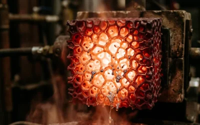
Metal inclusion defects ruin even well-made investment castings. High-value parts turn into costly scrap.
Ceramic filters protect foundries from non-metal debris. But they only work well with correct setup—placement alone isn’t enough.
Using ceramic filters in investment casting means more than just putting a filter in your mold. You need to pick the right pore size for your alloy type. Control how fast you pour. Watch the filter during cooling to see if it’s getting full. Each choice affects your final casting quality and how many good parts you get.
This guide covers the five-step process for adding ceramic filters. You’ll learn the exact methods that make filtration work. We show you where to place filters for best results. You’ll spot common problems before they happen. Plus, you can measure the quality gains that prove your filter investment pays off.
Ceramic Filter Placement in Investment Casting
Filter location inside your gating system controls your entire filtration process. Wrong placement creates turbulence. You get uneven mold filling. Quality drops fast.
Your filter must do three jobs: capture dirt, keep flow rates steady, and smooth the metal stream. These jobs matter. They decide if your casting works or fails.
Most foundries handle placement without planning. Process engineers see a bad casting and add a filter to the mold tree. No buying strategy. No system. Just trial and error.
The gating system has several placement zones. Each zone changes how metal flows:
-
Cup placement controls starting flow rates and sealing. Get this wrong and flow problems appear throughout the pour.
-
Runner placement balances filtering with flow speed. Thin-walled castings need this. You need high flow rates to fill the mold. You also need to filter debris.
-
Gate placement smooths the metal one last time before it enters the cavity.
Testing shows the difference between filter types. Water flow tests through different sizes show real flow rates. We measure volume per time unit, not just PPI ratings. High-speed video shows if you’re getting smooth flow or bursts. The exit stream tells the story. 3D-printed filters give you smooth streams every time. Foam filters produce random, uneven flow patterns. Eight different foundries ran the same tests and got these results.
Filter size matters for your gating design. Standard sizes run 0.5–1.0 inch for small gates. Larger systems need 2.0–4.0 inch filters. Match the size to your metal needs. Too-small filters block flow and cause defects. Too-large filters cost more and take up space in tight gating setups.
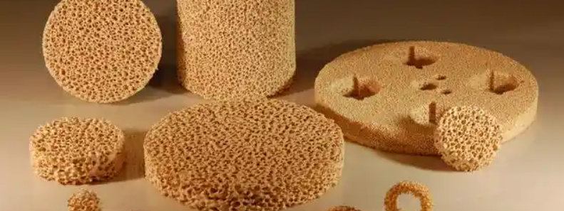
Step 1: Select the Right Ceramic Filter for Your Alloy
Your alloy type decides which ceramic filter material you need. Get this wrong and you’ll melt the filter or let debris pass through.
Match the temperature first. Aluminum alloys pour at 850°C max. Use Alumina ceramic filters for these jobs. The material handles the heat without breaking down. Grey and ductile iron needs Silicon Carbide ceramic. It survives up to 1500°C—well above the 1200°C pour temperature for most iron work. Carbon steels and alloy steels run hotter. Zirconia ceramic filters work up to 1740°C. Pour at 1650°C? You’re safe. Steel alloys that exceed 1700°C need zirconia foam. Nothing else handles that kind of heat stress.
Pore size controls what gets trapped. Filters come in PPI ratings: 10, 15, 20, and 30. Higher numbers mean smaller holes. Aluminum alloys work best with 1.8–2.3 mm holes. That equals PPI 20–15. The sweet spot sits at 2.0 mm. You capture most oxide films without slowing the pour. Grey iron uses 1.5–2.3 mm (PPI 30–15). Ductile iron needs bigger openings at 2.0–2.8 mm (PPI 20–10). The graphite nodules in ductile iron flow better through larger pores. Carbon steels need even bigger holes: 2.5–5.0 mm works for HSC 15–5 filters.
Flow area changes your production speed. Grey iron filters need about 50% flow area. Need maximum filtration? Drop below 50%. You’ll catch more debris but pour slower. Ductile iron requires at least 50% flow area. Less than that and your metal won’t fill thin sections. The mold sits there half-full.
Material Options for Extreme Conditions
Heat shock breaks standard filters. You pour hot metal into a cold mold. The temperature drop cracks weak ceramics.
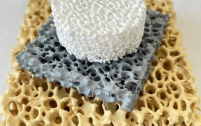
Magnesium stabilized zirconia handles the worst shock. The material flexes instead of breaking apart. Zirconia-mullite blends give moderate shock resistance at lower cost. Pure alumina works on a tight budget. Mullite sits in the middle—better than alumina, cheaper than zirconia.
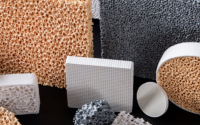
Filter shape affects flow patterns. Foam filters start flowing at 1000 mL/sec. Honeycomb filters begin at 600 mL/sec. Foam filters shed almost no debris during the pour. Honeycomb versions may release particles. You might need to clean your gating system between pours.
Testing multiple filter types saves money later. Your first choice often doesn’t work right away. How complex is your casting? That matters. Your inlet design matters too. The mold material changes how fast metal flows. Run samples with different PPI ratings. Try various materials. Track your scrap rate for each test. The data tells you which filter cuts defects and keeps production speed up.
Custom filters cost more up front. They fit your exact mold shape. Flow rates match your specific alloy chemistry. You get better results than forcing standard sizes to work.
Step 2: Prepare and Install the Filter During Mold Setup
Cut your ceramic filter to match your gating system’s exact size. Measure twice. Cut once. The filter needs to fit snug between your mold halves. No gaps. No overlap. Gaps let dirty metal skip the filter entirely. You end up with debris in your casting.
Size the filter based on your metal flow needs. Small investment castings use 0.5–1.0 inch diameter filters. Large industrial parts use 2.0–4.0 inch filters. Match the thickness to how much metal you’re pouring. Thin filters handle small pours. Big pours need thick filters. Otherwise, metal breaks through. Make sure the filter diameter covers your full runner or gate opening. Don’t leave any space for metal to sneak around the edges.
Put the filter in the first mold half before you close it. Lay it flat on the surface where your gating system moves the metal. Most setups place the filter between the runner and gate. Some foundries drop filters in the pouring cup. Others put them just before the casting cavity. Try both spots with your alloy. See which one cuts down on defects.
Secure the Filter and Close the Mold
Lock the filter down before you join the mold halves. The filter can shift off-center during setup. Metal just flows around it then. Drop-in style filters stay put with gravity alone. The filter’s weight keeps it stable as you close the mold. Thin-wall castings are fragile. They need extra support. Pin the filter corners with small ceramic posts. The posts keep it in place without blocking metal flow.
Bring your mold halves together along the parting line with even pressure. Line up the grooves and ridges on each side. The ceramic filter sits between the matching surfaces. You’ll feel pushback as the halves squeeze the filter edges. Press too hard and the ceramic cracks. Too gentle and you get gaps. Target 1/32 inch of space around the filter edge.
Tighten mounting bolts to 5 ft-lbs (6 Nm) of torque. Put high collar lock washers on to stop bolts from coming loose during the pour. Pouring vibration works standard bolts free. Use thread locking compound if your molds run multiple times each day. Check bolt tightness after every third pour on high-volume runs.
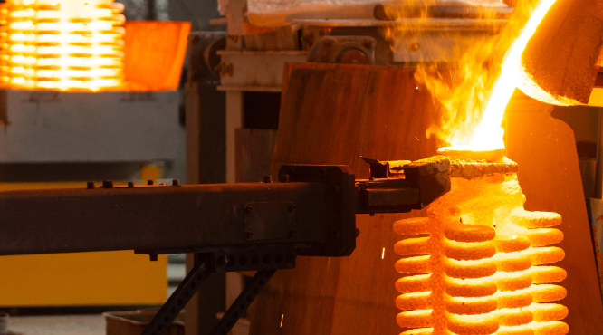
Step 3: Execute Controlled Metal Pouring Through Filter
Your filter sits in the mold. The halves are locked tight. Prime the filter before metal enters the casting cavity.
Priming pulls air out of the filter pores. Air trapped in ceramic blocks metal flow. You get uneven filling. Some sections of your casting stay empty. Apply vacuum to the exit well at 0.1–10 kPa per second. A fan or air venturi pulls the air through. Keep pulling until molten metal flows into the filter. Metal appears on the downstream side. That’s your signal it’s working.
The priming sequence has six steps. First, pour enough molten metal to cover the filter’s upstream face. The metal level needs to stay above the filter top—no exposed ceramic. Second, seal the outlet in your exit well. Use a sealable cover or a movable closure. Third, turn on your vacuum system. Increase suction at a steady pace. Don’t spike the pressure. Fourth, watch for metal breakthrough. A conductive probe works best. It completes an electric circuit on contact with metal. Fifth, release the vacuum fast. A solenoid valve dumps pressure to atmosphere in under one second. Sixth, remove your seal. The outlet opens. Metal flows through the filter and into your mold.
Post-priming flow needs minimal pressure. Your metal sits on the inlet side. Gravity alone pushes it through the filter. You don’t need high head pressure anymore. The filter stays wetted. Metal keeps moving.
Monitor Flow Rates During the Pour
Porosity controls how fast metal moves. More open area means faster flow. Particles in your melt clog pores as you pour. The effective flow area drops. Pick a filter with extra capacity. Your flow rate stays stable even as particles build up on the surface.
Semi-continuous casting needs a steady metal flow. Stop-and-go flow creates cold shuts. The casting surface shows lines where metal stopped and restarted. Pick your filter based on sustained flow, not peak rates.
Aluminum melts need extra head pressure at startup. Surface tension holds metal back at the pore openings. Smaller pores need more pressure to break through. Your melt temperature affects this. Hot metal flows easier. Chemical makeup plays a role too. Silicon content changes surface tension.
Electromagnetic pump systems with ceramic foam filters handle up to 100,000 pounds of aluminum per filter. The pump back flushes debris after each cycle. Filters mount at the pump bottom intakes. Metal flows up through the ceramic. Trapped particles fall back down during the flush cycle.
Position your filter in the pour cup or at the mold inlet. Both spots work. Cup placement catches debris before it enters your gating system. Inlet placement gives you smoother flow right before the cavity. The filter acts as a flow rectifier. Turbulent metal goes in. Calm, predictable metal comes out. You avoid splash. Air bubbles don’t form. Your casting fills without porosity defects.
Step 4: Monitor Solidification and Filter Performance
Track your filter while the metal cools. Flow pattern changes signal problems before they ruin your casting.
Ceramic filters build strength fast during solidification. Most filters reach full strength within 1-3 days after the pour. High-density ceramic materials resist water penetration even after long exposure to cooling fluids. Your filter keeps its shape and trapping ability through the whole cooling cycle.
Watch for flow rate drops during the pour. Metal slowing down means particles are piling up on the filter surface. Clogging cuts your flow area. Turbulence increases downstream. The metal stream gets choppy instead of smooth. Stop pouring before backpressure pushes metal around the filter edges.
Test permeability to see how well your filter worked. Low permeability after cooling means the filter stayed intact. Cracks or breakthrough spots show up as high permeability zones. Water penetration tests catch these failures. Pour water through your cooled filter at standard pressure. Measure volume over time. Good filters block 95% or more of the water flow.
Track Contaminant Capture Rates
Heavy metals in your melt get trapped at different rates. Copper, lead, and zinc removal works best at low to moderate levels. Filter performance drops when metal contamination exceeds 500 ppm in the base alloy. High chloride levels up to 40,000 ppm still filter well through quality ceramic materials.
Check your filter after each pour on critical castings. Cut it open. Look at the debris layer on the inlet face. Thick buildup means your filter caught lots of particles. Clean ceramic on the outlet side confirms nothing broke through. Dark streaks or metal penetration on the exit face shows filter failure. You need a different pore size or material for that alloy.
Step 5: Post-Casting Inspection and Filter Removal
Pull the casting from your mold after it cools. Wait until the metal reaches room temperature. Rushing causes thermal shock. This damages delicate features.
Remove the filter in sequence. Start with the bottom section. Move to the middle. Finish with the top piece. Deep molds need a ladder. Industrial setups use custom platforms. Filters over 50 pounds? Use a pulley system. The filter breaks into chunks during removal. Keep the pieces. You’ll inspect them later to check how well filtration worked.
Visual inspection comes first on every casting. Look at all surfaces under good light. Document what you find. Write down where each defect sits. Measure the size. Take photos of problem areas. Pull out any parts that don’t meet your quality standards. Set them aside before they mix with good castings.
Surface and Subsurface Defect Detection
Liquid penetrant testing catches hidden cracks. Clean the casting surface first. Remove grease and oil with solvent. Blast off sand and slag with compressed air. Nonferrous alloys need a light etch—0.001 to 0.002 inches deep. This opens up tight surface breaks. Brush on the penetrant solution. Wait 10 minutes. The liquid seeps into cracks. Wipe the surface clean. Spray developer. Cracks show up as bright lines against the white background.
Magnetic particle inspection works on ferrous metals. Note: This only works on iron-based metals. Magnetize your casting with a yoke or coil. Spray iron powder on the surface while the magnetic field stays active. Particles gather at flux leakage points. You can spot cracks as shallow as 0.003 inches. Surface breaks show up sharp. Subsurface defects appear as fuzzy lines.
Filter Performance Analysis
Cut open your used filter after removal. The inlet face shows a debris layer if filtration worked right. Oxide particles pile up on the surface. They form a cake that traps smaller particles as metal flows through. No buildup? Your pore size was too large. Particles passed straight through into your casting.
Check for porosity defects in critical areas. Fine voids cause leaks in pressure-tight parts. Oil passages fail leak tests. This happens because porosity connects to the surface. Oxides trapped behind the filter create these defects. They come from your furnace lining or contaminated scrap. Aluminum castings need extra attention. Hydrogen gas creates porosity even with perfect filtration. Feed risers must deliver clean metal during solidification. Skip this step? You get scattered pinholes throughout the part.
Document your filter condition for each pour. Track debris thickness. Note breakthrough spots and crack patterns. The data tells you if your current filter spec works. Or if you need to adjust it for the next production run.
Optimizing Filter Efficiency: Best Practices and Troubleshooting
Filter retention rates change drastically across different materials and makers. PTFE hydrophilic filters capture 96-100% of particles in HPLC work. Millex PTFE filters average 98.3% retention with just 1.8% variation. Some makers hit perfect 100% capture rates across every test batch. Regenerated cellulose filters? They don’t perform well. RC filters with 0.45 μm pores trap just 48.2% of particles. Smaller particles? Retention drops to 15.8%. More than 80% of debris goes straight through into your column.
Match Pore Size to Your Column Specs
Standard HPLC runs use 0.45 μm filtration. Smaller particle columns need finer filters. A 2 μm column works fine with 0.45 μm filters. Sub-2 μm columns clog fast with standard filters. Drop to 0.22 μm or 0.1 μm pore sizes for these setups.
Maker consistency matters as much as pore rating. One PTFE supplier showed 78.8% retention on some batches. Other lots from the same company dropped to 20.9%. Another maker held steady at 98.5% across every test. Not all filters with the same pore size work the same. Test multiple lots before you commit to large orders.
Measuring the Impact: Quality Improvements and ROI
Foundries track defect rates after adding ceramic filters to their casting process. Scrap costs drop. Customer returns fall. These gains appear in the first three months.
Healthcare quality programs use proven ROI metrics. Casting quality works the same way. Track hard numbers and soft signs. Hard data: scrap rate %, rework hours per batch, warranty costs. Soft signs: supplier ratings, customer scores, repeat orders. Healthcare gets 250-400% ROI in 18 months from process fixes. Casting delivers similar results with good tracking.
Use four categories: defect counts, efficiency marks, cost cuts, and time to improve. Defects include surface holes, internal gaps, oxide bits, and size errors. Count defects per 100 castings before and after filters. Efficiency covers pour time, mold fill rate, and filter changes. Avoided scrap drives your biggest savings. Track progress over 90 days minimum. Shorter periods miss the real gains.
Track two types of data for the complete view. Financial numbers show dollars saved each month. Process data shows stability gains. Use both together. One aerospace foundry cut defects by 73% with zirconia filters for steel. Scrap dropped from 12% to 3.2% in six months. Material savings covered filter costs in four months. Complaints fell 89%. They won two new contracts from their quality gains. ROI grows beyond simple cost cuts.
Watch how fast your team adopts the change. Quick use means clear benefits. Slow use points to training needs or wrong equipment. Track these numbers each week in quarter one: defects per batch, filter life hours, metal use rate, labor hours per good part. Check monthly to spot trends early.
Conclusion
Ceramic filters in investment casting make the difference between good castings and great ones. Follow these five steps: pick the right filter for your alloy, install it correctly in the mold, control your pouring technique, monitor performance, and inspect after casting. You’re not just filtering molten metal. You’re building precision into every part.
The proof is clear: fewer defects, better mechanical properties, and solid ROI. Serious foundries can’t do without ceramic filters. Filter efficiency depends on more than the product. It depends on how well you control temperature, pouring speed, and placement.
Your next casting run is a chance to use these practices. Start with one thing—maybe better filter selection or improved pouring technique. Then measure what happens. Small changes like these often separate average castings from exceptional ones.
Want better casting quality? Use these techniques in your next production cycle. Track the improvements. Your profits will show the difference.