ceramic casting turns liquid or semi-liquid ceramic materials into precise, complex shapes. Choose the wrong method? You’ll waste time, money, and end up with poor quality products.
Slip casting brings traditional simplicity. Gel casting delivers advanced precision. Each technique works best for specific uses.
Making delicate porcelain tableware? Industrial ceramic parts? Advanced technical ceramics? Understanding what are the different types of ceramic casting impacts your production efficiency. It affects your final product performance too.
This guide covers five primary ceramic Casting methods. You’ll see their strengths and limitations side by side. We provide practical selection criteria to help you pick the right technique for your needs.
You’ll also find critical quality control checkpoints. Plus, we show you solutions to common production challenges that can make or break your ceramic manufacturing process.
Slip Casting – The Foundation Method
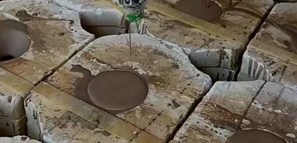
Slip casting uses a simple physics principle. Porous plaster molds absorb water from liquid ceramic slip. This builds up a solid layer against the mold wall. The technique is centuries old. It still forms the backbone of ceramic manufacturing.
The Casting Slip Formula That Makes or Breaks Your Product
Your slip composition controls everything. Particle size must stay below 5 micrometers in water or alcohol. This ultra-fine mix ensures smooth flow and even spread.
Water content hits a critical point: below 32% by weight. Get this precise balance using deflocculants like Sodium Silicate (N grade, diluted 50/50 with water) mixed with Soda Ash.
Target specific gravity between 1.75 and 1.80. Here’s the math: 437g of slip divided by 250g of water equals 1.75. Test your viscosity using flow time. Your slip should fill a 250ml graduated cylinder in 25 seconds.
The deflocculant sequence matters:
– Start with 90% Sodium Silicate in your initial mix
– Add Darvan #7 in small increments as needed
– Use up to 20g of Magnesium Sulfate for final adjustments
Step-by-Step Slip Preparation Protocol
Mix 15g of Barium Carbonate first. Blend for 5 minutes until dispersed. Add your 90% Sodium Silicate solution. Mix another 5 minutes to activate the deflocculant.
Here’s the crucial part: add dry slip powder to water slowly. Mix well and scrape the container walls to prevent lumps. Screen everything through a 30-mesh sieve. This catches any remaining clumps.
Shell Mold Casting for Complex Geometries
The lost-wax shell mold process gives you new options for intricate shapes. Coat your wax pattern with calcium sulfate-bonded investment. Build up at least 0.25 inches thickness across all surfaces.
Dry the coated pattern. Cure at 1000°F to vaporize the wax and form your rigid shell mold. Let it cool to room temperature before you continue.
Pour your ceramic slip. High-purity fused silica quartz aqueous mix works great here. Wait until your desired wall thickness forms. Pour out the excess slip. You can peel away the wet shell mold if your design requires it.
For added strength, coat a fused silica ceramic “eggshell” layer over the 909 Investment shell before wax cure. This reinforcement lets you remove the mold safely for draining excess slip.
Pressure Cuts Production Time Fast
Standard atmospheric casting takes 2 hours to build a 12mm wall thickness. Use 8 MPa pressure? That same wall forms in just 1 minute. The pressure differential pushes water through the mold faster. This speeds up layer buildup.
Real-World Applications and Limitations
Slip casting works great for creating hollow gas turbine vanes from advanced materials like SiC, Si₃N₄, and sialons. Manufacturers make body armor components and precision aerospace models with complex features. Think nose tips, fins, and winglets that other methods can’t match.
The tradeoff? Production rates stay slow. This isn’t your mass-production solution. Slip casting fits specialized applications. Here, precision and complexity matter more than volume.
Pressure-Assisted Slip Casting Variants
Manufacturers pump slip into molds at 500–1500 psi. No need to rely on gravity alone. This turns casting from a slow manual craft into an industrial tool.
High-Pressure Slip Casting (HPSC) for Sanitary Ware
Modern HPSC systems work in two pressure stages. Pre-fill your mold at 3–4 bars to establish initial contact. Then ramp up to 10–13 bars for complex shapes like toilet bowls and sinks.
The process runs mostly hands-free:
Automated cycle breakdown:
– Clean porous resin molds with water/air jets and add release agent
– Close the 2-part mold setup with no manual help
– Inject slip at staged pressures
– Let excess water drain through mold pores until you hit target wall thickness
– Open mold via PLC-controlled hydraulics
– One operator manages up to 12 battery-type molds at once
Yutai machines add micro-pressure consolidation right before demolding. This stops warping during removal. Their hydraulic pumps keep uniform pressure across large mold surfaces.
After demolding, drill drainage holes, trim flash, and smooth surfaces. Pre-dry pieces to specific moisture content before inspection, glazing, and final firing.
Robotic Rotational Casting for Art and Prototypes
Pneumatic syringes mounted on robotic arms open new creative paths. Configure your end-effector with 500 ml syringes connected to compressed air quick-connects. Best injection pressure sits at 30 psi per syringe (80 psi total system max).
Program custom toolpaths with 90°, 180°, or 270° rotations. Fasten 4-part plaster molds using packing tape for easy setup.
Test results show the limits:
|
Test |
Rotation Pattern |
Slip Volume |
Outcome |
|---|---|---|---|
|
1 |
Color sequence, 1 min/side + 30 min dry |
550 ml |
Successful multi-color layers |
|
2 |
2.5 min each side (6 sides) |
10 ml increments |
Unstable build, excessive drainage, collapse |
The lesson: Inject larger volumes (200+ ml) with good drying intervals. Small fills (10 ml) create drainage problems and structural failure.
Specialized Applications Beyond Basic Hollow Ware
SACMI BTDG machines cast cups with handles in one integrated step. DORST systems produce tableware and sanitary ware in near-net shapes. This cuts post-processing time by a lot.
You can use porcelain, stoneware, bone china, vitreous china (VC), and fine fire clay (FFC). Technical ceramic makers use pressure variants for advanced materials that need precise size control.
Mold material matters: High-quality porous resin resists slip absorption better than standard grades. Poor resin clogs fast. This forces frequent cleaning cycles that kill productivity.
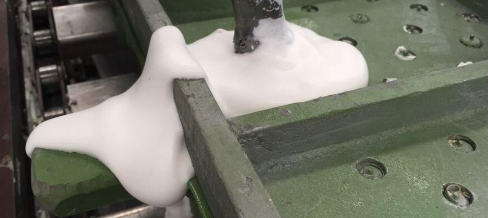
Tape Casting – For Thin Film Production
Tape casting creates ceramic films thinner than a human hair. The process spreads ceramic slurry under a precision blade. The slurry moves onto a substrate. This method leads production of solid-state battery parts, multilayer capacitors, and fuel cell membranes.
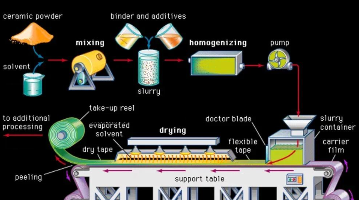
Dispersion Prep and Casting Parameters That Work
High-energy ball milling spreads your ceramic powder evenly. Load SPEX 8000M mills with yttria-stabilized zirconia media in sealed jars. Test your solid loadings between 51-57 wt% to find what works best for your material.
Set your doctor blade gap at 300 μm to produce 50 μm finished films. The shear rate hits around 30 s⁻¹. Want thinner films? Try 200 μm blade gaps. Just adjust your slurry thickness.
Cast onto silicone-coated PET substrate. Run your casting speed above 30 cm/min. Use the shortest blade tongue length. You get smooth, graded tapes without streaking.
Dry cast films at 70°C for 24 hours in controlled ovens. Post-process by pressing at 225 MPa in PEEK dies (1.26 cm² area). This gives you dimensional stability.
Performance Gains You Can Bank On
Tape-cast 50 μm LPSCl films deliver 11X reduction in area specific resistance (ASR). Compare that to cold-pressed 500 μm binder-free pellets. Ionic conductivity stays the same between both forms.
The tape casting equipment market shows growing demand. Current value sits at USD 1.2 billion (2024). Projections show growth to USD 2.5 billion by 2034 (CAGR 7.5%). Energy storage drives this growth. So do electronics and advanced ceramics manufacturing.
Gel Casting – High Strength Green Bodies
Organic monomers and crosslinkers turn ceramic slurries into rigid gel networks. This chemistry process creates green bodies with tensile strength over 3 MPa. That’s 5 times stronger than dry-pressed powder at 0.6 MPa. The extra strength lets you machine complex shapes before firing.
The 50 Vol.% Loading Target That Stops Distortion
Solid loading percentage decides if your green body holds its shape or fails. Push your ceramic content above 40 vol.% minimum. Aim for 50 vol.% for best results.
The interface height ratio shows you when slurry stability peaks. Target ≥99.5% for optimal retention time. Drop below this? Particles settle in uneven patterns. Your castings warp and crack during drying.
Curing time drops as loading increases:
– 35 vol.% loading: 357 seconds (exceeds safe 300s retention window)
– 50 vol.% loading: 225 seconds (faster cure from increased particle surface area)
Higher powder concentration cuts down free solvent volume. This speeds up reactions. You get shorter processing cycles. Plus, better dimensional control.
Monomer-to-Crosslinker Ratios for Maximum Green Strength
Set your monomer/crosslinker ratio between 2:1 and 6:1. Higher ratios boost gel strength. Your wet green bodies resist warping during demolding. Dry strength improves for safer handling before sintering. You can machine parts easier for post-forming work.
Processing Protocol for High-Performance Components
Ball mill your ceramic slurry 12 hours at 120 r/min under argon atmosphere. This stops oxidation. It also ensures complete mixing.
Add DMA (monomer) and TBPB (initiator). Stir 30 seconds—enough to mix without air bubbles.
Cast into PTFE molds. Cure 30 minutes at 70°C to form your wet green body. Demold with care. Dry at 80°C for several hours until moisture evaporates.
Degrease at 450°C for 90 minutes to burn out organic binders. Final sintering at 1050°C for 30 minutes makes your ceramic structure dense.
Initiator Concentration Controls Gelation Timing
AZAP initiator concentration changes when reactions start. Test results on alumina/zirconia systems show clear patterns:
|
AZAP Amount |
Gelation Behavior |
Strength Development |
|---|---|---|
|
0.25-0.5% |
Starts at 70°C hold |
Slower modulus buildup |
|
1-2% |
Begins before 70°C peak |
Rapid strength gain |
Use 1-2% AZAP for faster production cycles. Lower concentrations (0.25-0.5%) need longer temperature holds. This slows throughput. You get no quality benefits.
Pore Architecture in Functional Ceramics
Gel-cast NiTi at 42 vol.% loading creates linked pore networks spanning 0-360 µm. Peak distribution sits at 80-160 µm with uniform skeletal structure. This controlled porosity makes gel casting perfect for filters, biomedical implants, and catalyst supports. Fluid flow matters in these applications.
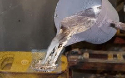
Hot Die Casting – Wax-Based Forming
Wax patterns form the base of Investment casting for ceramic parts. The process injects molten wax into precision dies. This creates exact replicas of your final part. The patterns get coated with ceramic slurry. These shells can handle extreme heat during metal or ceramic pouring.
Wax Injection Settings That Control Pattern Quality
Temperature control makes or breaks your pattern quality. Inject your paraffin and microcrystalline wax blend between 70–90°C. This range keeps wax fluid enough to fill fine details. Go hotter? Your pattern warps. Go cooler? You get partial fills and cold joints.
Size changes you must account for:
– Linear shrinkage rate: 0.9-1.1% as wax cools
– Round features see the most shrinkage
– Calculate oversizes into die sizes to hit final specs
Die prep takes a big chunk of cycle time. Spray water-based mix of waxes and oils onto die surfaces before each shot. This lubricant step uses about 30% of your total cycle time. Skip it or rush it? Patterns stick to dies and tear during removal.
High-Pressure Die Casting Cycle Breakdown
Total cycle times run 30–300 seconds based on part complexity. Here’s how that time breaks down:
Phase-by-phase timing:
– Filling: Under 100 milliseconds at metal speeds over 100 km/h
– Solidification and cooling: Fast heat drop from >100°C/s down to 1°C/s
– Ejection: Safe removal after enough cooling
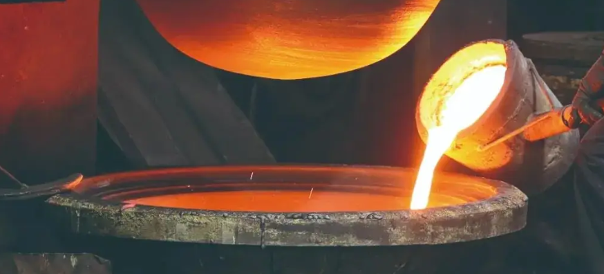
Die surface temps settle around 250°C during production runs. Molten aluminum enters at about 700°C. This heat shock stresses both die and lubricant layer.
Use pressure above 600 bar during solidification. This pressure feeds material into shrinking areas. You stop porosity and keep size accuracy.
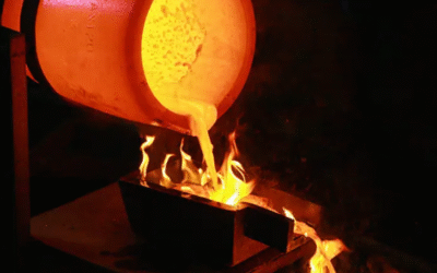
Investment Shell Strength Needs
Ceramic shells around wax patterns need strong mechanical strength. Target up to 10 MPa to handle heat stress from molten metal at 1,400–1,600°C. Shells also take internal pressure between 0.1–0.5 MPa during pouring.
Dewaxing and Firing Steps
Remove wax patterns in steam autoclaves at 150–200°C under 7–10 bar pressure. Steam melts wax fully without cracking ceramic shells. Drain molten wax for reuse in future patterns.
Preheat empty shells to 540–1,090°C before pouring. This step cuts porosity by 15–20%. It also cuts heat shock from hot material hitting the mold.
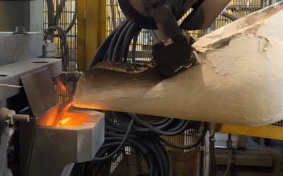
Pour at controlled rates between 0.5–2 kg/s. Slower fills stop cold shuts where metal fronts meet. Faster pours risk turbulence and trapped gas. Solidification takes 10–60 minutes after pouring based on section thickness.
Production Ability and Surface Quality
die casting tolerances hold ±0.004″–0.010″ across production runs. Makers produce 5,000–10,000+ parts from single die sets before tool replacement.
You can achieve surface roughness (Ra) of 32–63 µin after finishing work. This removes small flaws from demolding and heat cycling.
Common failure to watch: Soldering happens at the die-pattern contact when friction gets too high. Lower removal temps reduce this risk. Watch lubricant spray patterns—air-sprayed application causes heat shock. Lubricant trapped in vents reacts with aluminum. This forms brittle compounds that damage dies.
Comparative Selection Criteria
Production volume, part complexity, material properties, and cost targets pull you toward different Casting Methods. Match these factors to technique capabilities using clear evaluation steps.
Volume-Complexity Matrix Mapping
Sort your decision into four groups. Base this on annual production volume and geometric complexity:
Low Volume (<1,000 units/year) + High Complexity:
– Gel casting wins for intricate shapes needing machining strength
– Hot die casting works for pattern precision beyond ±0.010″ tolerance
– Green strength above 3 MPa supports detailed features. It prevents breakage.
High Volume (>10,000 units/year) + Low Complexity:
– Pressure-assisted slip casting automates hollow ware production
– One operator manages 12 molds at once
– Cycle times drop 40% compared to manual methods
High Volume + High Complexity:
– HPSC systems at 10-13 bars handle sanitary ware with undercuts
– Robotic rotational casting produces art pieces with multi-color layers
– 200+ ml injection volumes prevent structure collapse
Low Volume + Low Complexity:
– Standard slip casting needs the lowest equipment investment
– 2-hour atmospheric casting fits prototyping budgets
– No pressure pumps or automation required
Weighted Scoring Model Application
Assign criterion weights totaling 1.0 across your priorities:
|
Criterion |
Weight |
Slip Cast Score |
Pressure Cast Score |
Gel Cast Score |
Tape Cast Score |
|---|---|---|---|---|---|
|
Unit cost |
0.35 |
85 |
65 |
60 |
45 |
|
Tolerance control |
0.25 |
60 |
75 |
85 |
90 |
|
Production speed |
0.20 |
40 |
85 |
55 |
70 |
|
Material flexibility |
0.20 |
90 |
70 |
80 |
50 |
|
Total Score |
– |
69.5 |
72.5 |
70.0 |
61.5 |
Calculate: Total Score = Σ(weight × score) where scores run 0-100 scale.
Material-Specific Selection Rules
Solid loading limits force technique choices:
-
Below 40 vol%: Tape casting works here. Slurries are too thin for other methods.
-
50-54 vol%: Gel casting optimal range. You get minimum defect rates.
-
Above 55 vol%: Pressure assistance required. Standard slip won’t consolidate.
Particle size constraints matter for film applications:
– 20 µm particles need minimum 50 µm film thickness (2-3× diameter rule)
– Finer than 5 µm enables slip casting across all techniques
Pairwise Comparison for Close Decisions
Two methods score within 5 points? Run head-to-head comparisons using 9-point preference scales:
Example: Pressure casting vs. Gel casting for aerospace vanes
-
Dimensional accuracy: 9 (extreme preference for gel casting’s 3 MPa strength)
-
Setup cost: 7 (strong preference for pressure casting automation)
-
Cycle time: 5 (moderate preference for pressure’s 1-minute walls)
-
Material waste: 3 (slight preference for gel’s precise volumes)
Sum weighted preferences across all criteria. The higher score identifies the winner for your specific application.
Quality Control and Common Challenges
Each casting method faces unique quality barriers. These barriers impact production costs and product reliability. Data from 2024 industry surveys shows 64% of ceramic manufacturers identify quality control as their top challenge—a sharp jump from 50% just one year earlier.
The Real Cost of Quality Failures in Ceramic Casting
Poor quality control hits your bottom line hard. Medical device recalls linked to ceramic component defects surged 115% since 2018. These failures cost the industry $5 billion each year. Rising material costs make rework even more expensive. You can’t afford to ignore quality metrics.
Top quality control obstacles you’ll face:
– Incomplete inspection data: 67% of manufacturers lack complete trust in their quality data
– Manual documentation errors: Paperwork takes time and introduces human mistakes
– Real-time defect detection gaps: Production environments make instant problem spotting hard
– Massive data storage needs: QC generates huge data volumes that overwhelm basic systems
Common Defects Across Casting Methods
Slip casting problems:
– Uneven wall thickness from inconsistent slip viscosity
– Surface cracks during drying (moisture gradients exceed stress limits)
– Mold contamination causing surface defects
– Incomplete filling in complex geometries
Pressure-assisted casting issues:
– Pressure changes create density variations
– Mold wear from repeated high-pressure cycles
– Early demolding causes green body damage
– Robotic injection errors in rotational systems (volume inconsistency, poor rotation timing)
Gel casting challenges:
– Early gelation blocks mold fill (AZAP concentration too high)
– Incomplete polymerization leaves weak zones
– Air bubble entrapment during mixing
– Particle settling occurs below 40 vol% solid loading
Tape casting defects:- Streaking from improper doctor blade setup- Thickness variations across film width- Substrate adhesion failures during drying- Particle clumping creates surface roughness
Root Causes You Must Address
Human error drives most quality problems. Typos in batch records happen. Process steps get forgotten. Material codes stay inconsistent across manual operations. 77% of organizations rate their data quality as average or worse.
Separate production systems prevent real-time quality tracking. Slip preparation uses one database. Casting uses another. Firing departments use a third. You lose traceability. Data format differences between stations cause integration errors.
Proven Solutions That Work
Deploy automated data collection at every process step. Replace manual entry with sensors. Track slip viscosity, pressure readings, temperature curves, and drying rates. This cuts human error. Plus, it builds complete audit trails.
Set up continuous monitoring dashboards. Create alert thresholds for critical parameters. Monitor solid loading percentage, cure times, and demolding forces. Catch deviations before they create scrap.
Create clear governance policies across departments. Define standard data formats for ceramic formulations. Cover process parameters and inspection results. Break down silos with unified quality management platforms.
Build smart remediation workflows. Defects occur—your system flags similar batches right away. It traces raw material lots. It recommends fixes based on historical patterns.
Build a quality-first culture. Train operators on root cause analysis. Share defect data with your team. Reward teams that improve processes rather than hiding problems.
Conclusion
The ceramic casting method you pick affects your production speed, part quality, and costs. Slip casting works great for complex shapes. Tape casting delivers precision for thin films. Each technique fits different industrial needs. Know the types of ceramic casting available. This helps you match the right process to your needs—high-volume production, exact dimensions, or strong green bodies.
We’ve looked at key factors: how complex your parts are, production volume, material traits, and costs. These give you a framework for choosing. Process selection varies by project. A prototype might work best with gel casting because of its strength. Mass production often needs the faster pressure-assisted slip casting.
Want to improve your ceramic manufacturing? Check your part specs against the criteria above. Talk to ceramic engineering experts. They can run feasibility tests for your materials and shapes. The right casting method does more than just produce parts. It brings out the full power of advanced ceramics in what you’re building.