Engineers and procurement specialists often ask: what is the difference between monolithic catalyst and ceramic honeycomb?
People sometimes use these terms as if they mean the same thing. But knowing their distinct features can save you from poor performance and expensive mistakes.
A monolithic catalyst is a complete catalytic system. Ceramic honeycomb acts as the structural base. This simple explanation doesn’t tell the whole story, though.
Surface area ratios matter. So does pressure drop performance. Thermal stability plays a role too. And you need to think about total cost of ownership. Each component offers unique benefits that impact your system’s efficiency, lifespan, and budget.
What Is a Monolithic Catalyst?
A monolithic catalyst is a single, solid structure. It combines the physical carrier and active catalytic material in one unit. Unlike loose powder or pellet catalysts, it has a fixed geometry—honeycomb channels. Gases flow through these channels by convection.
The structure starts with a ceramic base. Cordierite is a common choice. Manufacturers shape it into square blocks with channels about 1 mm × 1 mm. A washcoat layer sits between the carrier and the active catalyst. This layer is often Al₂O₃ or zeolites. It bonds the catalytic material firmly to the channel walls. Advanced versions skip inert carriers. They use nano-array structures or pure catalyst formulas instead.
Active components change based on what you need:
-
Precious metals: Platinum, palladium, and rhodium treat automotive exhaust
-
Mixed metal oxides: MnFeOₓ, MnCuOₓ, and MnNiOₓ work well for BTEX oxidation (benzene, toluene, ethylbenzene, xylene)
-
Combination formulas: ¼ palladium on MnFeOₓ monolith gives the best results. It fully converts BTEX at temperatures ≤200°C
Making these catalysts follows clear steps. First, select the carrier. Then apply the washcoat support. Next, add the active catalytic layer to the channel walls. Dry and heat the structure to lock in thermal stability. Mass loss stays minimal (<0.018%).
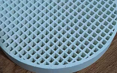
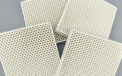
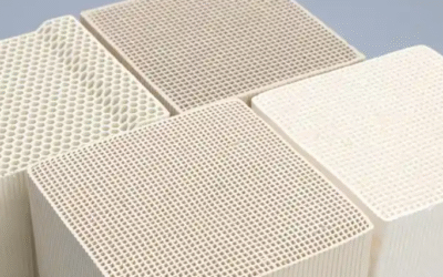
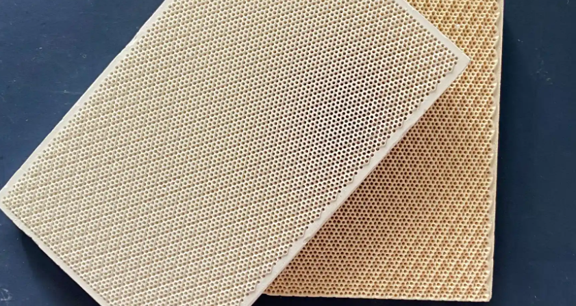
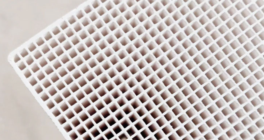
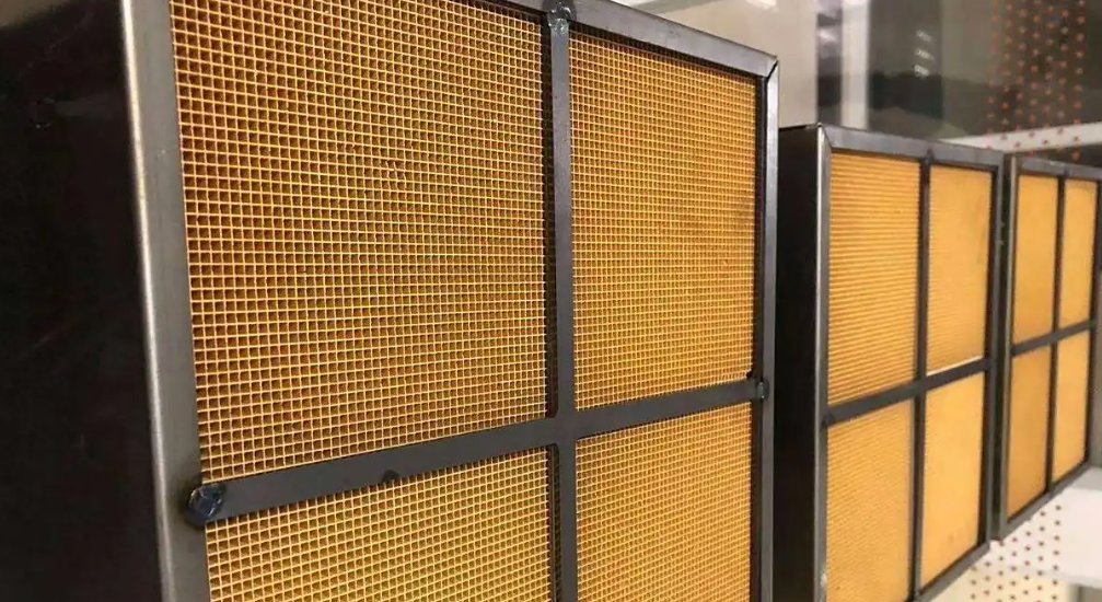
What Is Ceramic Honeycomb?
Ceramic honeycomb is a multi-channel grid structure. It’s made of parallel ceramic channels arranged in a honeycomb pattern. This design gives you maximum surface area for reactions and filtration. Plus, gas flows through without blockage.
The structure uses cordierite-mullite materials. These contain aluminum oxide (Al₂O₃) and silicon dioxide (SiO₂). Cordierite forms the base because it handles heat well. Thermal expansion stays very low at 2.1–6.5 × 10⁻⁶/K between 20°C and 1000°C. Temperatures can reach 1350°C without damage.
Geometric shapes change based on what you need:
-
Cell densities: Range from 0.7 to 400 cells per square inch (CPSI). Common sizes include 100, 200, 230, 260, and 300 CPSI
-
Channel counts: A standard 150×150×300 mm block holds 25 to 3,600 channels. More channels create more surface area
-
Wall thickness: Thin walls (0.43–0.73 mm) with small holes (1.8–3.0 mm) create huge surface areas. These reach up to 1310 m²/m³
Take a 60×60 hole setup as an example. It delivers 1310 m²/m³ active surface. At the same time, it keeps 64% free cross-section. So you get minimal pressure drop. You also get maximum contact area for reactions.
The structure has porosity from 61% to 81%. This lets gases move into the ceramic walls. The result? Better reaction efficiency.
Structural Design Differences Between Monolithic Catalyst And Ceramic Honeycomb
The physical setup separates these two parts. This affects your system performance. Monolithic catalysts and ceramic honeycombs build differently, even though they often work together.
Single-Piece vs. Multi-Channel Architecture
Monolithic catalysts use a single-piece cordierite structure. Wall thickness ranges from 0.15 to 0.25 mm. This uniform channel design cuts backpressure by 20-30% compared to traditional pellet beds. The design has no gaps or dead zones. Gases can’t bypass active surfaces.
Ceramic honeycombs feature multi-channel porous ceramic construction. Cell densities span 400 to 1,200 CPSI. Higher surface areas reach 2 to 4 m²/g. The flow paths through porous walls create 10-15% higher pressure drop than monolithic designs. You need to balance conversion efficiency against energy costs. This trade-off plays a key role.
Shape Options and Their Performance Impact
Cylindrical designs dominate automotive applications—used in 70% of cases. Diameters range from 100 to 200 mm. The radial flow pattern delivers 15% better gas distribution uniformity. Maldistribution drops by 10% compared to other shapes. This symmetry stops hotspots and cold zones. These zones hurt catalyst lifespan.
Rectangular blocks maximize space in non-circular exhaust systems. Space use improves 20-30% with rectangular housing. Aspect ratios of 2:1 limit efficiency to 85% because of edge effects. Corner areas see reduced gas velocity. Conversion rates drop in these spots.
Irregular (custom) shapes fit specialized applications like truck mufflers. Packing density increases 25% in tight spaces. Manufacturing costs rise 40% due to complex tooling. Flow uniformity decreases 5-8% at bends and transitions. This can create local inefficiencies.
Channel Density Impact on Flow Distribution
Higher CPSI creates more contact area. But it also increases resistance:
|
CPSI |
Wall Thickness (mm) |
Pressure Drop (kPa at 10 m/s) |
Conversion Efficiency (%) |
Application |
|---|---|---|---|---|
|
400 |
0.25 |
2.5 |
92 |
Heavy-duty diesel |
|
600 |
0.17 |
4.0 |
95 |
Passenger cars |
|
900 |
0.13 |
6.5 |
97 |
High-performance |
|
1200 |
0.10 |
9.0 |
98 |
Euro 6+ standards |
Mass transfer improves 25% once CPSI exceeds 900. Square channels deliver the best flow uniformity. You get less than 5% variance across the cross-section. Hexagonal channels show 10% variance. This creates uneven loading on the catalyst surface.
Compactness and Space Efficiency
Monolithic structures reduce volume by 40% versus granular catalysts at the same performance levels. Length-to-diameter ratios of 3:1 to 5:1 keep backpressure below 5 kPa. A standard automotive catalyst measures 3.5 inches diameter × 6 inches length (0.11 L) at 600 CPSI. Compact designs shrink volume 25% through thinner walls. Efficiency stays the same.
Ceramic honeycombs provide 30-50% higher geometric surface area per liter of volume. Oval shapes boost space use by 15% in tight packaging scenarios. This extra surface area supports higher catalyst loading. Conversion demands can go up without losing performance.
Material Composition and Catalyst Loading
Base materials determine how your system handles heat and structural stress. Catalyst loading controls reaction efficiency and cost. These two factors define performance across industrial and automotive applications.
Ceramic Substrate Materials
Cordierite (2MgO·2Al₂O₃·5SiO₂) dominates as the honeycomb substrate. Its thermal expansion coefficient stays low at 2.1–6.5 × 10⁻⁶/K from 20°C to 1000°C. This stops cracking during rapid temperature changes in exhaust systems. The material survives continuous exposure up to 1350°C.
Mullite-cordierite blends boost mechanical strength by 15-20% for heavy-duty diesel applications. These composites maintain porosity between 61% and 81%. Gas molecules penetrate deep into the ceramic walls. Reaction sites expand beyond just the surface layer.
Silicon carbide (SiC) substrates serve specialized high-temperature needs. Thermal conductivity reaches 20-30 W/m·K—about 10x higher than cordierite. This uniform heat spread prevents localized overheating. You’ll find SiC in diesel particulate filters where regeneration temperatures exceed 600°C often.
Catalyst Loading Strategies and Performance
Active component distribution varies widely by application:
Automotive three-way catalysts use precious metal loadings of 1-3 g/L total volume. Platinum makes up 1 wt% of the washcoat layer. Promoter metals like rhodium add 10 mol% relative to the main metal on CeO₂ support. This combination converts NOx, CO, and hydrocarbons at once at >95% efficiency above 300°C operating temperature.
PEMWE (Proton Exchange Membrane Water Electrolysis) systems face different limits. Commercial iridium catalyst loadings sit at 2-3 mg/cm². These achieve Ir-specific power around 2 MW/kgIr at 88% efficiency. Research targets drop below 0.01 mg/cm² to reach 100 MW/kgIr. Lower loading cuts material costs. But it requires better distribution.
Loading density impacts mass transport:
-
High loading: Uniform coating covers the entire surface. Full PTL (Porous Transport Layer) top void acts as O₂ inlet. You get consistent performance but higher material costs.
-
Medium loading: 75% PTL top void remains as inlet. Material savings of 25% with minimal efficiency loss.
-
Low loading: Non-uniform coating leaves 50% PTL top void as inlet. Higher current density per active site creates O₂ transport challenges. Gas saturation needs to stay around 80% in channels for optimal mass transport.
Bimetallic and Complex Formulations
Advanced catalysts combine multiple metals for synergistic effects. Researchers tested 48 bimetallic supported catalysts for specific reactions. Ir/Cr combinations achieved >99% yield converting feedstock to 5-(ethoxymethyl)furfurylmethanol.
Acrylonitrile production catalysts use precise mole ratios: P, K, Cr, Mo on Al₂O₃/SiO₂ support with VSb₅WSn promoters. Optimized formulations reach 79% yield compared to 64% with standard compositions. Machine learning models predict performance with R² values of 0.90-0.98 using conversion, selectivity, and yield data.
Low-loaded sintered catalyst-coated membranes (CCM) create better triple-phase contact areas. Gas removal improves 12-18% versus traditional high-loading setups. This is key in electrochemical applications. Bubble formation limits current density there.
Durability and Mechanical Strength
Monolithic catalysts handle tougher conditions than bare ceramic honeycombs. The washcoat and active metal layers protect against heat shock and mechanical stress. Cordierite substrates in monolithic units stay intact through >10¹¹ thermal cycles in car applications. Service life goes beyond 20 years in well-designed systems running above 600°C.
Ceramic honeycomb substrates alone resist fatigue less well. Failure probability sits at 1% under standard testing conditions. Data analysis of monolithic catalyst durability shows R²=0.996 linear fit reliability across 80% of high-strength performance data. This steady performance shows how catalyst layers stabilize the base structure.
Mechanical Stress Distribution
Wall thickness affects fracture risk. Thin-walled ceramic honeycombs (0.10-0.13 mm at 1200 CPSI) face 15-20% higher stress buildup at channel intersections during heat expansion. Monolithic catalysts with thicker walls (0.17-0.25 mm at 400-600 CPSI) spread loads better. Crack growth rates drop 30-40% compared to ultra-thin designs.
Vibration tolerance varies between designs. Heavy-duty diesel systems create 5-8 Hz low-frequency vibrations plus 200-500 Hz high-frequency pulses during regeneration cycles. Monolithic structures with precious metal anchoring deliver 25% better vibration damping than uncoated ceramic. The washcoat layer works like a micro-cushion. It soaks up vibration energy. This stops major failure at mounting points.
Surface Area and Catalytic Efficiency
Catalytic performance scales with accessible surface area in most reaction systems. Geometric structure affects actual reaction rates. This separates monolithic catalysts from bare ceramic honeycombs in measurable ways.
Effective Surface Area Calculations
Monolithic catalysts create 2-4 m²/g active surface through washcoat distribution. Ceramic honeycombs deliver 1310 m²/m³ geometric surface at high cell densities (60×60 configuration). This difference matters for calculating true catalytic efficiency.
Researchers studying Co₃O₄ catalysts found reaction rate constants scale with specific surface area (SSA). Higher SSA samples showed faster H₂O₂ decomposition. But per unit area, intrinsic rate constants stayed constant—around the same value across all samples. Total exposed surface controls overall reaction speed. Material composition alone doesn’t.
The formula k_surface = k_mass / SSA reveals true efficiency. Mass-based rate constants drop with lower calcination temperatures (higher SSA). Surface-normalized constants remain steady. You’re measuring the same active sites per square meter, just in different total quantities.
Contact Efficiency and Mass Transfer
Gas-catalyst contact improves with higher surface area. A K-promoted CoO₂ catalyst demonstrated this. Tight soot contact lowered ignition temperature by 340°C compared to loose contact. The bulk promotion effect exceeded surface-only promotion. More catalyst surface touched the reactant.
Electrochemical surface area (ECSA) measurements show different patterns. High and low surface area copper electrocatalysts produced comparable ethylene yields per unit ECSA. Increased surface didn’t boost product formation in proportion. Post-operation analysis revealed morphological changes generated new active areas during the reaction itself. Starting surface area didn’t predict final performance.
Platinum nanocrystals follow shape-dependent efficiency rules. Artificial neural network models achieved >0.9 squared correlation mapping surface features to activity. Optimal performance came from less spherical shapes with <20% {110} facets. Surface geometry matters as much as total area.
Real Conversion Rate Data
|
Catalyst Type |
SSA Condition |
Rate Constant Behavior |
Conversion Impact |
|---|---|---|---|
|
Co₃O₄ (high SSA) |
High |
Fast k_mass |
Full H₂O₂ → O₂, rapid foam volume rise |
|
Co₃O₄ (low SSA) |
Low |
Slow k_mass |
Delayed oxygen release, slower visible reaction |
|
Cu (high ECSA) |
High |
Constant per ECSA |
C₂H₄ yield unchanged vs. low ECSA |
|
Pt optimized |
{110}<20% |
Peak efficiency (R²>0.9) |
Maximum activity/selectivity ratio |
|
K₀.₂₅CoO₂ |
Promoted surface |
-340°C ignition shift |
Tight contact critical for performance |
Automotive applications confirm this link. Surface area loss explains significant percentage variations in hydrocarbon conversion efficiency. A 10% SSA reduction can drop HC conversion by similar margins. Regular monitoring prevents performance degradation.
Active site density stays proportional to SSA in hydrogenation and oxidation reactions. Number of catalytic sites increases with exposed surface. But ECSA-normalized activity shows the real story. Transformation during operation often creates more impact than initial surface area measurements suggest.
Thermal Performance
Good heat management keeps catalytic systems running reliably. Poor heat control leads to early failure. Monolithic catalysts and ceramic honeycombs manage heat stress differently. Their material makeup and structure create these differences.
Temperature Resistance Limits
Cordierite-based monolithic catalysts run non-stop at 1350°C. They show no structural damage at this heat. The washcoat layer bonds active metals straight to the channel walls. This bond holds strong through fast temperature changes of 200-400°C per minute during cold starts. Thermal expansion stays low at 2.1–6.5 × 10⁻⁶/K from 20°C to 1000°C. Cracking risk falls by 40% compared to pellet bed systems under the same thermal cycling.
Bare ceramic honeycomb substrates handle the same 1350°C max temperature. But they lack protective coating layers. So surface micro-cracks form 15-20% faster after repeated heating cycles. The porous ceramic walls (61-81% porosity) absorb heat in a different way. Heat spreads less uniformly across the cross-section. Hot spots form at 5-10% higher temperatures than nearby areas.
Silicon carbide (SiC) substrates deliver better thermal conductivity at 20-30 W/m·K. That’s about 10 times higher than cordierite. This spreads heat uniformly. It stops temperature gaps above 50°C inside the structure. You’ll find SiC in diesel particulate filters. These filters burn soot at 600-800°C on a regular basis.
Heat Transfer Efficiency
Active catalyst layers change heat transfer traits. Washcoat thickness of 20-50 μm adds thermal resistance. But precious metal particles (1-3 g/L loading) work as tiny heat sinks. They soak up reaction energy at the spot. Surface temperature spikes drop by 30-40°C during high-conversion work compared to bare substrates.
Channel shape controls how heat gets removed by convection. Higher cell densities (900-1200 CPSI) boost surface contact. But they slow down gas speed in each channel. Heat transfer rates drop 10-15% at very high CPSI values. The 400-600 CPSI range gives you the right balance. It matches surface area with flow speed for the best heat control in most car applications.
Industrial Applications
Manufacturing growth across North America creates huge demand for monolithic catalysts and ceramic honeycomb substrates. The U.S. announced 244,000 reshoring and foreign direct investment manufacturing jobs in 2024 alone. Job creation since 2010 reached 1.7 million positions. This boom drives specific catalyst and substrate needs across multiple sectors.
Semiconductor and Advanced Packaging Facilities
CHIPS Act funding put $50 billion toward semiconductor R&D and manufacturing. Multi-billion dollar awards went to fabrication plants and packaging operations through Q3 2025. These cleanroom spaces need high-purity gas treatment systems. Monolithic catalysts remove trace VOCs and dopant gases before wafer contamination happens. Ceramic honeycomb filters capture sub-micron particles in HVAC systems.
Cell densities of 900-1200 CPSI meet Class 1 cleanroom standards. Ultra-thin walls (0.10-0.13 mm) keep <2 kPa pressure drop at required air speeds. Precision motion control systems create point-source emissions. So do vacuum equipment and automated material handling. Compact monolithic designs fit tight equipment spaces better than traditional pellet beds.
Energy and Electrification Manufacturing
IRA tax credits under Section 45X boost domestic production of clean energy parts—solar modules, wind turbines, batteries, switchgear, and power electronics. Battery lines need solvent vapor recovery systems. Electrode coating releases N-methylpyrrolidone (NMP) and other organic solvents. Monolithic catalysts burn these vapors at 300-450°C with >98% destruction efficiency.
Lamination, winding, potting, and testing equipment creates local heat. Honeycomb ceramic heat exchangers recover 60-75% of waste thermal energy from curing ovens and formation chambers. The 1310 m²/m³ surface area at 60×60 hole patterns transfers heat well while keeping <5 kPa pressure loss.
Solar module plants use monolithic oxidation catalysts for silane control. Semiconductor-grade silicon production releases silane (SiH₄) during deposition. Precious metal loadings of 1-2 g/L convert silane to harmless silica particles at 250-350°C. This stops explosive gas buildup in exhaust ducts.
AI Data Centers and Grid Infrastructure
Data center construction drives demand for electrical switchgear, thermal management systems, and backup power units (UPS). These facilities handle >50 MW power loads in single buildings. Transformer and busbar coating releases aromatic hydrocarbons. Monolithic VOC oxidizers treat exhaust at flow rates >20,000 m³/hr with minimal energy use.
Ceramic honeycomb substrates appear in UPS battery ventilation systems. Lead-acid and lithium-ion batteries release hydrogen during charging. 400-600 CPSI honeycomb filters with activated carbon washcoats absorb hydrogen. They prevent concentration above 4% LEL (lower explosive limit).
Manufacturing construction spending hit ~$100 billion in 2025, up from $58 billion in 2024. Megaprojects totaled $134 billion through Q3 2025 (+47% year-over-year). This spending creates ongoing substrate and catalyst replacement markets as new plants start operations.
Industrial Automation and Robotics Integration
The industrial automation market grew from USD 221.64 billion in 2025 toward USD 325.51 billion by 2030. Robot installations in the U.S. jumped +12% to 44,303 units in 2023. Operating robot stock across the Americas reached ~520,000 units. Paint booths and coating stations in appliance, automotive parts, and durable goods plants all need catalytic afterburners.
Robotic welding cells make metal fumes and ozone. Ceramic honeycomb filters catch particles >0.3 μm at 85-92% efficiency in single-pass setups. Collaborative robots (cobots) in food and beverage packaging make less demanding emissions. But vision inspection systems still need particle-free air. HEPA-grade ceramic substrates deliver 99.97% filtration of contaminants that mess with optical sensors.
Smart factory use shows 95% of manufacturers using or testing Industry 4.0 tech. Leaders call automation the top driver for the next 5 years (86% agreement). Sensor networks (50% IoT use) and data analytics (70% cloud use) enable predictive maintenance on catalyst systems. Temperature, pressure drop, and conversion tracking prevents surprise shutdowns.
Conclusion
What is the difference between monolithic catalyst and ceramic honeycomb? Understanding this helps you make smarter, cost-effective decisions for your industrial needs. Monolithic catalysts excel in high-performance emission control. They offer superior catalytic efficiency and lower pressure drop. Ceramic honeycomb structures give you exceptional heat resistance and mechanical strength. Plus, they cost less.
Your choice depends on your application needs. Think about operating temperatures, space limits, emission standards, and your budget. Automotive exhaust systems need maximum conversion efficiency. Monolithic catalysts work best here. High-temperature industrial processes need structural strength and long life. Ceramic honeycomb delivers better value in these cases.
Don’t settle for a one-size-fits-all approach. Check your specific operational parameters. Talk to material specialists. Request performance data from suppliers. The catalyst support structure you choose today affects your system’s efficiency. It impacts maintenance costs and regulatory compliance for years. Make an informed choice—your process performance depends on it.