You invest time and resources into a pour. Then you find inclusions, slag contamination, or surface defects. The final product is compromised. Every iron casting professional knows this frustration.
Having ceramic honeycomb filters isn’t enough. You need to know how to use ceramic honeycomb filters in iron casting to get the best filtration performance.
Struggling with inconsistent casting quality? Need to meet strict aerospace specifications? Want to cut rejection rates? Master the proper selection, preheating, installation, and handling of ceramic honeycomb filters. Your results will change.
What Is a Ceramic Honeycomb Filter and How Does It Work in Iron Casting?
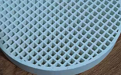
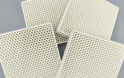
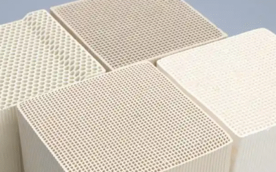
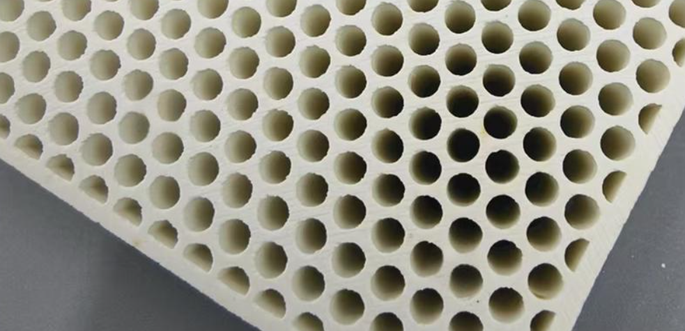
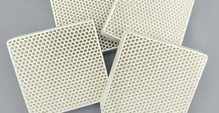
A ceramic honeycomb filter handles high-temperature filtration. It’s built from mullite or cordierite-mullite materials. Parallel straight-through channels run through the entire structure. The cells come in different shapes: square, round, hexagonal, or triangular. Density ranges from 100 to 400 mesh. Square sizes start at 37×37 mm and go up to 81×81 mm. Round ones range from Φ30 to Φ90 mm. Thickness sits between 12 and 22 mm.
Material composition matters here. Mullite-based filters pack over 85% mullite content. Al2O3 levels hit 40-50% (some reach 55.4%). Cordierite-mullite versions have Al2O3 at 35-37%. Bulk density spans 0.7 to 1.8 g/cm³. These specs give you maximum operating temperatures of 1300-1500°C. Iron casting applications usually run at 1390°C. Thermal shock resistance reaches up to 800°C. Dimensional change stays minimal—less than 0.2% at maximum temperature.
How the Filtration Process Works
The filter removes over 90% of inclusions larger than 30μm. Three distinct methods make this happen:
Direct interception blocks large slag particles and oxides. Molten iron flows through straight channels. The physical barrier stops these contaminants right away.
Boundary layer capture traps fine particles on channel walls. Each channel has high surface area. This creates multiple contact points. Impurities stick to these points during metal flow.
Cake layer filtration builds an impurity layer at channel entrances. This layer grows as pouring continues. It catches smaller and smaller inclusions over time.
Maximum filtration weights depend on size. A 35 mm filter handles 35 kg of grey iron. An 81×81 mm unit processes up to 200 kg. Flow rates stay stable at 3-18 kg/s for grey iron. Performance remains consistent even with high inclusion loads.
Turbulence Conversion Technology
Turbulent molten iron enters the filter at high velocity. It splashes and moves chaotically. The straight parallel channels force even distribution across all pathways. Channel walls dampen turbulent eddies. Friction reduces kinetic energy. The result? Stable laminar flow (Reynolds number below 2000) exits the filter.
This conversion cuts air ingress by over 50%. Less oxidation happens during pouring. Metal yield increases 2-5% compared to unfiltered pours. Preheat filters to 1700-2000°F before use. This drops defects from porosity and voids by 60%.
Picking the Right Ceramic Honeycomb Filter for Iron Casting
Mesh density controls what gets filtered out. Ceramic honeycomb filters in iron casting come in 100, 200, 300, or 400 mesh. All of them remove over 90% of particles larger than 30μm.
Got typical iron oxides and slag? The 100-300 mesh range works best. You get good flow rates. Plus, it catches most of the bad particles.
Need to trap smaller stuff below 30μm? Use 300-400 mesh. Got grey iron with bigger slag chunks? A 100 mesh keeps your pour rates faster.
Size Your Filter Based on Pour Weight
Filter size matters. A 37×37 mm square filter handles up to 35 kg of grey iron. The 50×50 mm size takes 70 kg. Big production runs? You’ll want the 81×81 mm filters. They process 200 kg.
Round filters work the same way. A Φ50 mm filter manages 50 kg of grey iron at 5 kg/second. Ductile iron flows slower. That same Φ50 filter drops to 3 kg/second and 40 kg total.
Check Your Alloy Needs
Grey iron is flexible. It works with 100-300 mesh and flows at 3-18 kg/sec.
Ductile iron needs more precision. Use 100-200 mesh with slower flows (2-12 kg/sec). This catches the particles that mess up nodular graphite.
Casting steel? Temperatures hit 1550-1580°C. Make sure your filter has at least 15 MPa compression strength. It must handle these extreme temps.
Custom shapes fit different gating systems. Thin profile filters work better in tundish setups than foam options. They stay strong too. You get less than 0.2% size change at max temperature.
How to Preheat Ceramic Honeycomb Filters
Thermal shock cracks ceramic honeycomb filters. Preheating stops this from happening. For iron casting, keep temperatures between 1700-2000°F (above 900°C). The filter body needs to match the temperature before molten metal touches it.
Control Your Heating Rate to Avoid Damage
Increase temperature by 100°C per minute from 350°C to 750°C. This slow rise protects the honeycomb walls from stress cracks. Heat too fast? You create temperature gaps between outer surfaces and inner channels. These gaps form tiny cracks that hurt filter performance.
Drop temperature by 200°C per minute during tests. This matches real regeneration without breaking the structure. Industrial furnaces running at 38 CFM keep heat even across the whole filter.
Three Steps for Safe Preheating
Step 1: Bring the filter inlet to 340°C. Hold it there for 5-10 minutes. This lets the ceramic expand evenly.
Step 2: Raise temperature to 650°C with steady heat. Watch the temperature along the length. Hot spots are bad. They put stress on certain areas and can destroy the filter.
Step 3: Lower to idle temperature in stages. Don’t let a hot filter cool too fast. Different filter shapes handle shock differently. But they all risk breaking without a slow cooldown.
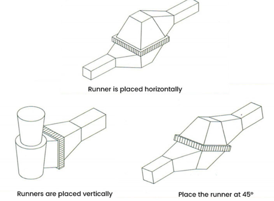
Installing Ceramic Honeycomb Filters: Placement Strategies for Different Casting Systems
Filter placement controls whether you get smooth flow or messy chaos. The location you pick affects filter efficiency, defect rates, and metal yield. Three main positions work in iron casting: pouring cup setup, tundish placement, and runner-gate setup.
Pouring Cup Installation for Direct Debris Capture
Cut the filter to match your gating size. Measure twice before cutting—precision matters. Fit the filter tight between mold halves with 1/32 inch edge clearance. Gaps let molten iron bypass the channels. You lose all filter benefits.
Secure thin-wall castings with ceramic posts at each corner. This stops filter movement during pouring. Place the filter in the pouring cup to catch debris before it reaches the gating system. Check for overlaps or voids along the edges. These create metal bypass routes that mess up your pour.
Prime the filter before full pouring starts. Pour enough metal to cover the upstream face first. Seal the exit well. Use vacuum at 0.1-10 kPa/sec until metal flows downstream. This stops air from getting trapped. It also ensures smooth cavity filling.
Tundish Horizontal Placement to Reduce Shrinkage
Position filters flat under the intersection cup or at the parting surface. Keep casting height at 20 cm or less. Pour molten metal against the cup wall—not onto the filter surface. Hitting the filter damages the honeycomb structure.
This placement creates smooth flow that cuts shrinkage holes. The flat position spreads metal across all channels. Roughness drops before metal enters the mold cavity.
Runner-Gate Configuration for Flow Control
Install filters between the runner and gate, or right at the mold inlet. Runners balance flow speed for thin-walled parts. Gates smooth metal movement before cavity entry. Honeycomb filters start flow at 600 mL/sec. Foam filters start at 1000 mL/sec. This slower rate cuts defects by 25%.
For non-stop casting, electromagnetic pumps mount at bottom intakes. A single filter handles 100,000 lbs of aluminum with automatic backflush systems.
Pouring Process and Flow Control with Ceramic Honeycomb Filters
Flow control decides if your castings pass inspection or go to scrap. Ceramic honeycomb filters in iron casting keep flow rates steady through the entire pour. The straight-channel design gives you predictable metal movement.
Maintaining Optimal Flow Rates During Pouring
Filter size controls how fast metal flows. A 37×37 mm filter processes grey iron at 3 kg/sec. The 81×81 mm size handles 18 kg/sec. Ductile iron moves slower—12 kg/sec for the same large filter. Aluminum drops to 9 kg/sec.
Round filters work the same way. A Φ50 mm unit flows grey iron at 5 kg/sec. Scale up to Φ90 mm and you get 18 kg/sec. Duct iron through that same Φ90 filter runs at 10 kg/sec.
These rates stay constant through the pour. Foam filters change flow speed as the cake layer builds. Honeycomb channels don’t have this problem. The straight-pore design holds strength and flow even with high impurity loads.
Pour Height and Impact Prevention
Keep molten metal drops under 20 cm. Higher drops hit the filter surface too hard. This breaks the honeycomb structure. Your filtration stops working right.
Pour metal against the cup wall—never onto the filter face. The wall stops initial turbulence. Metal then flows across the filter entrance without trouble. This cuts splash defects. It stops air from getting trapped.
Laminar Flow Generation for Defect Reduction
Turbulent metal carries trapped air and creates splashing. The parallel channels turn this chaos into stable laminar flow. Cross-sections show a stagnant layer forms along channel walls. This layer traps fine particles. Those particles never reach the mold cavity.
The result? Macro shrinkage drops fast. Voids from turbulence vanish. Solidification becomes easier to predict and control.
Maximum Filtration Capacity by Size
Each filter handles specific metal weights before it fills up:
|
Size (mm) |
Grey Iron (kg) |
Ductile Iron (kg) |
Aluminum (kg) |
|---|---|---|---|
|
37×37 |
35 |
25 |
15 |
|
40×40 |
40 |
30 |
20 |
|
50×50 |
70 |
58 |
40 |
|
81×81 |
200 |
174 |
122 |
Go beyond these weights and filtration efficiency drops. Flow resistance goes up as channels fill with trapped inclusions.
Zero Backpressure Growth Advantage
Honeycomb filters keep backpressure steady through the pour. Foam filters show growing resistance as the cake layer gets thicker. This change affects fill patterns. Metal behavior becomes hard to predict.
The straight-channel design stops pressure buildup. Cell densities from 60 to 400 cells per square inch give you different flow options. Higher porosity gives you stronger filtration and faster flow rates. This combo keeps metal moving without pressure spikes. You avoid turbulence and incomplete fills.
Impurity Removal Efficiency and Inclusion Control
Ceramic honeycomb filters remove over 90% of inclusions larger than 30μm. Three distinct mechanisms work together to do this. The straight-channel design creates a large surface area. This traps non-metallic particles as molten iron flows through. Real foundry data shows ceramic honeycomb filters in iron casting achieve 99% removal rates for iron oxides and aluminum compounds under controlled conditions.
Selective Removal of Different Inclusion Types
Not all inclusions behave the same. Iron (Fe³⁺) and aluminum (Al³⁺) oxides get removed at rates above 99% when pH stays between 3.5 and 5.25. Copper-based inclusions (Cu²⁺) also hit over 99% removal in this range. The filter keeps valuable alloying elements intact. Manganese retention stays above 90%. Nickel retention exceeds 90%. Cobalt retention holds at 80% or higher.
This selectivity happens because different materials drop out at different pH levels. Iron and aluminum start dropping out at pH 4.0 to 5.2. Nickel, cobalt, and manganese need pH above 6.7 before they precipitate. The honeycomb channels create boundary layers. These layers trap unwanted inclusions. They leave the elements you need in the final casting.
How the Filter Cake Layer Captures Slag
A filter cake builds at channel entrances during pouring. This layer forms as the first impurities hit the filter surface. Fast metal flow under inert atmosphere protection stabilizes this cake. The boundary layer gets thinner as flow conditions improve. This traps slag and debris while keeping metal chemistry stable. Total metal loss during filtration stays minimal: manganese 0.39%, cobalt 0.25%, nickel 0.42%.
High-Temperature Performance and Thermal Shock Resistance
Ceramic honeycomb filters work at 1300-1500°C in iron casting. Material chemistry decides if they survive these extreme temperatures. Mullite-based filters have over 85% mullite. Al₂O₃ levels sit between 40-55.4%. Cordierite-mullite versions carry 35-37% Al₂O₃. These mixes resist thermal shock up to 800°C temperature difference.
Maximum Operating Temperature Specs
Grey iron casting runs at 1390°C. Ductile iron reaches similar heat. Steel casting goes higher—1550-1580°C. Mullite filters handle all three alloy types. No structural failure occurs. Advanced ceramics melt at 3400°C. This gives huge safety margins. Size change stays under 0.2% at max service temperature. Channel shape stays intact through repeated heat cycles.
Thermal Shock Resistance During Fast Temperature Changes
Temperature drops create the biggest stress. Molten metal at 1390°C hits a filter preheated to 900-1000°C. This 400-500°C shock happens in seconds. The ceramic absorbs this change without cracking.
Cordierite works best here. Low thermal expansion (1.5-2.5×10⁻⁶/°C) cuts internal stress during cooling. Mullite gives higher mechanical strength (compression rating 15+ MPa). But shock tolerance is a bit lower. Both materials survive the pour with correct preheating.
Rupture temperature difference (ΔT_cr) changes with starting temperature. Tests show filters at 100°C starting temperature handle similar thermal shock as those at 1600°C. But filters at 800°C starting temperature perform much worse. This creates a danger zone. Don’t store or handle filters near 800°C before pouring.
Performance Through Multiple Casting Cycles
Factory data shows honeycomb filters keep their structure through 5-10 pours. This works within capacity limits. The straight-channel design stops stress points that make foam filters collapse. Heat fatigue resistance needs controlled heating and cooling rates. Keep heating at 100°C/minute from 350-750°C. Cool at 200°C/minute max during regeneration cycles.
Post-Casting Handling and Disposal
Used ceramic honeycomb filters in iron casting need proper care after each pour. Most foundries use them once and discard. Remove the filter from the gating system after the metal hardens. Look for visible cracks or spots where metal broke through the channels.
Filter Condition Assessment Methods
Shredder leftover analysis shows where dirt and debris collect. Sort filter pieces by size: 10-40 mm, 40-120 mm, and pieces larger than 120 mm. This early sorting shows how well the filter blocked debris before you dispose of it.
Heavy leftovers go through magnetic sorting. Metal scrap gets recovered and sold. Non-metal leftovers (NFR) show how much the filter blocked during use. More NFR means better filtering happened.
Disposal Economics: Single-Use vs. Reusable Filters
Throwaway filters cut out all cleaning costs. You don’t need labor for detinning or moving them. Reusable filters take time to process. Recovery stops during cleaning cycles. Foundry rejects, chips, and turnings sell as small scrap or dirty scrap. Throwaway filters create more waste but save processing labor.
Casting waste processing handles 250-800 tons per day in large facilities. Total disposal from casting operations reaches 123.5-138 million tons per year in baseline measurements. Casting waste makes up 62% of total processed material through baling and shredding systems.
Material Recovery Rates
Auto cast aluminum hits 91% total recycling. Collection rate reaches 99.7%. Heavy gauge aluminum achieves 95% melt yield. Light gauge does worse because of oxide losses in landfills. Just 0.58% of intake gets crushed to hulks for final shredding. Aluminum oxide goes to landfill after recovery tries.
Batch numbers on filters track back to casting quality. Scrap yield ID reaches 96% accuracy after removing odd results.
Industry-Specific Applications: Aerospace, Automotive, and Heavy Machinery
Aerospace foundries face huge demand pressures. Airbus holds 8,617 outstanding orders. Boeing carries 6,528 open orders. These backlogs push production to levels that can’t accept casting defects. Engine makers and MRO facilities need ceramic honeycomb filters in iron casting to meet strict quality standards.
Aerospace Engine Components: MRO Growth and Quality Requirements
Engine MRO demand grows at 3.2% CAGR from 2026-2035. Engine work will claim 53% of total MRO spending. This shift creates massive demand for replacement castings. Turbine housings need zero defects. So do structural brackets and mounting components.
AI-driven predictive maintenance cuts unscheduled downtime by 35% (Delta Airlines data). Fewer emergency part orders result. But replacement components need tighter tolerances. Honeycomb filters deliver the inclusion control aerospace specs demand. They remove over 90% of particles above 30μm. This stops micro-defects that cause failures at altitude.
US aerospace and defense AI spending hits $5.8 billion by 2029—3.5 times 2025 levels. Quality engineers now mix AI analytics with traditional inspection. Data skills in job postings jump from 9% (2025) to 14% (2028). This digital shift needs casting processes that create consistent, traceable quality data. Ceramic filters give you repeatable performance metrics batch after batch.
Automotive Drivetrain Castings: Legacy Fleet Support
Engine component production continues despite electric vehicle growth. Legacy fleets run longer service cycles. Hybrid powertrains still need traditional cast iron blocks and cylinder heads. Grey iron flows at 3-18 kg/sec through honeycomb filters. This matches automotive production line speeds.
Commercial vehicle fleets adopt fuel-saving digital twins. These systems track component wear patterns. Replacement parts must match OEM specs precisely. Honeycomb filtration removes slag that causes size problems and early wear.
Heavy Machinery: Defense and Construction Equipment
Large-scale additive manufacturing changes military logistics. But cast components still dominate heavy machinery frames, engine blocks, and structural parts. Defense contractors need resilient logistics. Ceramic honeycomb filters handle the high-volume pours needed for equipment updates.
Construction equipment faces similar demands. Excavator arms, loader frames, and crusher housings use ductile iron. Honeycomb filters process ductile iron at 2-12 kg/sec. The slower flow rate works well for these thick-section castings.
Conclusion
Master ceramic honeycomb filters in iron casting and watch your operation change. You’ll move from making acceptable parts to delivering top quality every time. Pick the right filter specs. Preheat them correctly. Place them in the right spot. Control your pour. These steps cut defects, lower machining costs, and boost customer satisfaction.
The numbers speak for themselves: foundries using these filters see up to 85% fewer non-metallic inclusions. Their castings also show better mechanical properties. Making aerospace components or heavy machinery parts? Proper filter use improves metal quality and cuts scrap rates. The payoff is real.
Your next step? Check your current casting process against the best practices we’ve covered here. Run a test program on one production line first. Measure how much porosity and surface finish improve. Then expand from there. The filter works as well as your technique allows. Precise preheating and placement separate small gains from major breakthroughs.
Your foundry’s quality revolution starts with one clean, well-filtered pour.