Ceramic honeycomb structures have changed how industrial filtration and catalytic processes work. But many engineers and procurement specialists still find it hard to pick the right setup for their needs.
These lightweight designs offer great surface area compared to their volume. You’ll find them in automotive emission control systems and heat recovery equipment. They power many industrial applications today.
Are you looking at substrate materials for a catalytic converter upgrade? Or maybe you need thermal management solutions for high-temperature environments? Either way, you need to know what ceramic honeycomb structures benefits and application scenarios exist. This knowledge helps you make smart, cost-effective choices.
What Ceramic Honeycomb Structures Offer: Benefits and Applications
The global honeycomb ceramics market shows strong growth. It was valued at USD 2,547.0 million in 2024. Experts project it will reach USD 4,442.1 million by 2032. This equals a compound annual growth rate of 7.20% through the forecast period. Stricter regulations drive this growth. Plus, automotive and industrial sectors keep advancing their technology.
Core Structure and Performance Framework
Ceramic honeycomb structures deliver value in three key ways:
Material Excellence: Cordierite-based substrates offer exceptional thermal stability. The coefficient of thermal expansion stays ultra-low at 0.4138 × 10^{-6} /K (30-800°C). Compare this to standard α-Al₂O₃ ceramics at 8.03 × 10^{-6} /K. Cordierite performs 20 times better. Specific heat capacity increases from 0.729 J/(g·K) at 50°C to 0.969 J/(g·K) at 800°C. This ensures consistent performance across all temperature ranges.
Geometric Advantages: The parallel channel design maximizes catalyst dispersion surface. At the same time, it keeps pressure drop minimal. Low specific heat means rapid catalyst activation during cold starts. This matters because emission standards must be met within the first 60 seconds of engine operation.
Chemical Efficiency: The structure supports key emission reduction reactions. CO converts to CO₂. NOx reduces to N₂ and O₂. Hydrocarbons convert to CO₂ and H₂O. Nano-sized precious metal particles (Pt, Pd, Rh) combine with optimized porosity. This achieves conversion efficiencies above 95% in modern applications.
What Are Ceramic Honeycomb Structures (Core Definition)
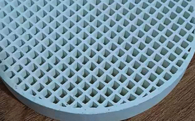
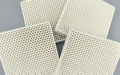
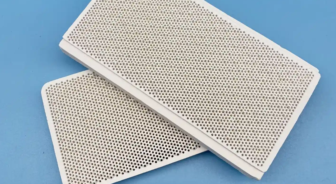
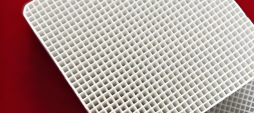
Ceramic honeycomb structures are integrated ceramic parts with thin partition walls. These walls form parallel polygonal flow channels in a honeycomb pattern. A thicker peripheral wall encloses these channels. You get a single unit that offers very high surface area. This works great for filtration, heat exchange, and catalytic reactions.
The design is different from solid ceramics. Solid ceramics use dense material all the way through. Honeycomb structures keep 76% free cross-section for fluid flow. The hollow-channel design creates surface areas over 150 m²/m³ in thin-wall setups. Plus, the structure stays lightweight. Pressure drop across the part stays minimal.
Physical Specifications That Define Performance
Partition walls measure 0.05–0.13 mm thick (average 0.104 mm). Thermal shock resistant types reach up to 1.1 mm. The peripheral wall is thicker than internal partitions. It averages 0.65 mm. Contact widths are optimized to stop edge chipping during making and use.
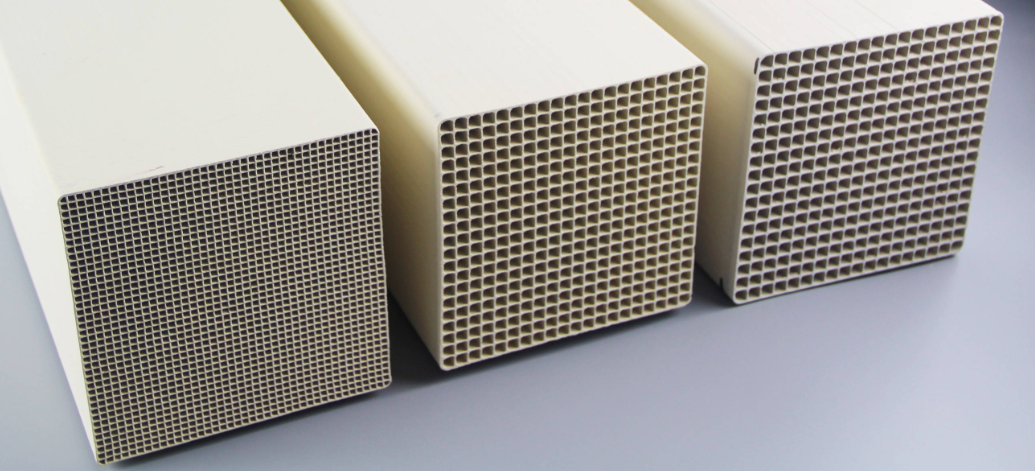
Cell density setups range from 25×25 to 50×50 cells per element. Channel widths sit around 26.0 mm in standard designs. Porosity stays above 30%. Most settle at 35%. This allows efficient gas diffusion. Structural integrity stays strong.
Corner reinforcement at wall junctions uses rounded edges. Mean radii measure 0.1 mm. Reinforcing portions extend 0.1–0.3 mm thick. They reach 1.2–15% from the periphery toward the center. This detail stops stress concentration points. These points could cause thermal cracking during fast temperature cycling.
Material Selection and Performance Trade-offs
Four main materials dominate honeycomb uses. Each offers clear advantages:
Cordierite leads in thermal shock resistance. Its ultra-low thermal expansion coefficient makes it perfect for automotive catalytic converters. These converters face fast temperature swings during cold starts.
Mullite gives you superior mechanical strength. You get 170 MPa flexural strength and 103.5 MPa tensile strength. This works for jobs needing structural durability up to 1700°C. Its thermal conductivity of 3.5 W/m-K and thermal shock resistance of 300°C ΔT balance thermal management needs.
Alumina delivers the highest modulus at 394 GPa. Tensile strength sits between 260–300 MPa. Its higher thermal expansion needs careful application selection.
Silicon carbide (SiC) excels in high-temperature settings. It demands both strength and thermal conductivity. Industrial heat recovery systems use it where fast heat transfer matters.
Mullite shows 150 GPa modulus and 2.0 MPa·m¹/² fracture toughness. It sits between cordierite’s thermal shock tolerance and alumina’s mechanical stiffness.
Manufacturing Process: Extrusion Dominance
Extrusion molding is the main production method. A slurry of ceramic materials passes through precision die slits. The slurry is cordierite from kaolin, talc, and alumina. These slits form both partition walls and the peripheral wall at the same time. Makers adjust slit widths through plating methods. This achieves exact channel sizes.
The extruded green body goes through controlled firing. It transforms into a single unit. For regenerative thermal oxidizers (RTOs), segmented designs use 25–60 cells. These act as drop-in replacement modules with integrated mixing zones.
This making method enables thin-wall precision. Solid ceramic casting cannot achieve this. Here’s the key difference: honeycomb structures offer hollow flow paths. Solid ceramics are dense and block flow. They have higher mass and thermal stress problems.
Key Material Properties That Drive Performance
Material science basics decide if a ceramic honeycomb survives harsh industrial conditions or breaks down. Thermal, mechanical, and chemical properties work together. They set the performance limit for each use.
Temperature Resistance and Thermal Stability
Refractory oxide materials go beyond what standard ceramics can handle. Zirconium oxide (ZrO₂) and silicon carbide (SiC) stay solid up to ~1700°C. You’ll find these materials in special brake pad mixes at 4-3% concentration. They keep friction stable and resist wear in hot contact zones. Temperatures jump during emergency stops.
The coefficient of thermal expansion (CTE) controls how well materials resist cracks. Materials that expand at different rates crack when heated or cooled fast. Titanium alloys show this in aerospace uses. They mix low thermal expansion with high strength for their weight. Parts won’t fail from shock as they move between normal air temperatures and extreme operating heat.
Structural Performance Under Load
The strength-to-weight ratio splits real designs from ideas that only work on paper. Three material types offer different benefits:
Aluminum alloys weigh less but stay strong. Young’s modulus sits at 69-73 GPa—much lower than high-carbon steel’s 200-215 GPa. This cuts weight without losing rust protection. Industrial heat exchangers use this to spend less on support structures.
High-carbon steel gives better yield strength and fights fatigue. The extra weight works fine for fixed equipment. Durability under repeated stress beats light weight here. Springs need materials that won’t bend after millions of squeezes.
Beryllium copper falls in the middle with 128-138 GPa modulus. It’s stiffer than aluminum but more flexible than steel. Plus, it conducts heat better.
Surface Chemistry and Friction Control
Brake pad formula BP1 shows how ceramic add-ins change performance. Barite makes up 26.5-30.5% of the mix. Adding 4% ZrO₂ and 3% SiC boosts the friction level through controlled roughness. These hard ceramics form stable contact areas.
Alumina (Al₂O₃) keeps friction steady across different temperatures. Steel, quartz, and silicate add-ins push the friction level higher. Real tests prove these mixes make pads last over 30% longer. They create better wear patterns where surfaces touch.
Core Benefits in Industrial Applications
Industrial facilities using ceramic honeycomb structures see real performance gains. These gains cut operating costs and make equipment last longer.
Operational Efficiency Through Reduced Downtime
Modern honeycomb catalyst systems cut unplanned downtime by 30-50% in factories. Sensors watch pressure changes, temperature shifts, and flow resistance across honeycomb channels. This live data predicts problems before they happen. You can spot substrate clogging or heat damage early.
Equipment runs 10-25% more efficiently with scheduled maintenance instead of emergency repairs. Production lines keep running. You get replacement honeycombs during planned maintenance, not rush orders.
Energy Consumption Optimization
Ceramic honeycomb heat exchangers in RTOs recover 85-95% of combustion energy. This heat warms up incoming air. Fuel use drops. Plants handling volatile organic compounds see 20-40% lower energy bills each month versus older systems.
Industry 4.0 platforms track how energy moves through the system. Airflow adjusts based on actual pollution levels instead of running full power all the time. Software like Energyaware gives operators remote control. They can fine-tune settings to match production needs.
Quality Control and Defect Reduction
Precision-extruded honeycomb substrates keep emissions within tight limits. Quality checks during extrusion catch size problems before firing. Automated systems reject substrates with walls outside ±0.015 mm tolerance.
Early control cuts waste in catalyst coating. Metal loading stays within ±2% uniformity across channels. Conversion efficiency holds above 95% for the product’s full life. Failed emissions tests drop sharply, so warranty claims go down.
Resource and Material Flow Optimization
Honeycomb structures pack maximum catalyst surface into small volumes. A single 150 mm × 150 mm substrate gives over 2.5 m² active surface in 400 CPSI designs. This efficiency cuts precious metal needs by 30-40% versus pellet catalysts with equal performance.
Analytics optimize when you replace parts. Fleet managers track how substrates perform across vehicles. Bulk orders group together during maintenance cycles. This timing cuts per-unit costs through volume deals. Plus, it eliminates rush shipping fees.
Critical Application Sectors
Ceramic honeycomb structures protect operations where failure means disaster. Many countries classify these sectors as critical infrastructure. Disruptions cascade into public safety emergencies. They can trigger economic collapse or national security threats.
Energy Sector: The Foundation of Modern Grids
Power generation facilities top every critical infrastructure list worldwide. The US CISA framework, Australia’s 22 critical assets, India’s NCIIPC guidelines, and EU NIS2 directives all place energy at the top tier. Ceramic honeycombs deliver this reliability through three pathways:
Gas turbine power plants use silicon carbide honeycomb recuperators. These reclaim exhaust heat at temperatures above 1400°C. The systems boost thermal efficiency by 15-20% in combined-cycle setups. A single 500 MW facility saves $2-4 million each year in fuel costs through heat recovery alone.
Hydrogen infrastructure relies on cordierite catalyst substrates for steam reforming. The honeycomb geometry supports platinum-group catalysts. These convert natural gas to hydrogen at 800-900°C with 75-80% efficiency. Germany’s hydrogen roadmap identifies this technology as essential. It helps transition district heating networks away from fossil fuels.
Oil and gas refineries install honeycomb reactors for desulfurization and NOx control. EU emissions rules mandate <200 mg/Nm³ NOx for new installations. Honeycomb SCR (Selective Catalytic Reduction) systems achieve <150 mg/Nm³ while processing 50,000+ Nm³/hour of flue gas.
Critical Manufacturing: Where Production Cannot Stop
India’s NCIIPC and US CISA both mark critical manufacturing as protected infrastructure. Ceramic honeycombs serve seven sub-sectors:
Pharmaceutical production needs contamination-free environments. Honeycomb thermal oxidizers destroy airborne pathogens and chemical vapors at 99.9% efficiency. They release no secondary pollutants. A vaccine manufacturing line processes 10,000 m³/hour of sterile exhaust through cordierite substrates coated with platinum catalysts.
Aerospace component forging uses honeycomb heat exchangers in 1600°C furnaces. Silicon carbide structures handle thermal cycling during titanium alloy processing. These parts stay stable within ±0.5% across 10,000+ heating cycles. This matters for safety-critical turbine blades.
Electronics fabrication needs ultra-clean air handling. Honeycomb filters with 400 CPSI capture submicron particles in semiconductor cleanrooms. Taiwan’s chip foundries use these substrates for Class 1 environments. A single dust particle ruins million-dollar wafer batches.
Emergency equipment production includes firefighting gear, hazmat suits, and medical ventilators. These depend on uninterrupted polymer processing. Honeycomb catalytic converters neutralize toxic fumes from thermoplastic extrusion at 300-450°C. They protect workers while meeting OSHA permissible exposure limits.
Transportation Systems: Mobility Infrastructure Protection
Every major framework lists transportation as critical. Ceramic honeycombs enable compliance across rail, maritime, and road networks:
Diesel locomotive engines meet EPA Tier 4 standards through SCR systems. These use 267 mm diameter cordierite substrates. A single freight train reduces NOx by 1.2 tons each year per locomotive. Rail operators avoid $50,000+ fines for emissions violations.
Maritime vessels operating in ECAs (Emission Control Areas) install honeycomb scrubbers. IMO 2020 sulfur caps require <0.5% sulfur content in bunker fuel or equivalent exhaust treatment. Honeycomb reactors achieve compliance while maintaining 18-22 knot cruising speeds. There’s no power loss.
Selection Criteria for Different Use Cases
Pick the wrong honeycomb substrate and you waste money. Worse, your equipment could fail. Four key factors help you choose the right ceramic honeycomb structure for your needs.
Temperature and Chemical Environment Drive Material Choice
Start with operating temperature. Cordierite substrates work up to 1350°C in oxidizing or neutral atmospheres. Their thermal expansion coefficient of 2.5×10⁻⁶/°C stops cracks during fast temperature changes. Gasoline particulate filters (GPF) below 800°C use cordierite because it handles cold starts well.
Mullite structures go up to 1500°C. Their CTE of 4.5-5.5×10⁻⁶/°C handles moderate thermal shock in diesel oxidation catalysts (DOC) running at 800-1200°C. This material fights off oxidizing environments and some reducing conditions.
Silicon carbide (SiC) works best in tough environments above 1200°C. Its thermal conductivity of 120 W/mK lets diesel particulate filters (DPF) handle high soot loads without overheating. SiC gives you 400 MPa mechanical strength—the strongest of the three materials. But it breaks easily under impact. Heavy vibration? You need careful mounting design.
Cost works backwards here. Cordierite costs the least per unit. SiC runs 3-4 times higher but lasts longer in extreme conditions.
Cell Density Balances Surface Area Against Backpressure
Cell density (measured in CPSI) controls two things that fight each other. More CPSI means more catalyst surface area. It also means higher pressure drop across the substrate.
200 CPSI designs give you 0.6 m²/L surface area with just 5 kPa pressure drop at 50 kPa backpressure. Heavy-duty diesel DOC systems use this setup. Engine power stays strong.
400 CPSI doubles surface area to 1.2 m²/L. Pressure drop jumps to 12 kPa. Standard GPF and light-duty applications use this density. It catches 90% of soot particles and keeps exhaust flow good.
600 CPSI substrates hit 1.8 m²/L at 20 kPa drop. High-efficiency SCR systems need this for NOx conversion above 95%. Here’s the trade-off: pressure drop rises with CPSI² divided by porosity.
900+ CPSI ultra-high-density filters deliver 2.7+ m²/L but add 35+ kPa backpressure. Ultra-low emissions DPF applications are the exceptions that need this. Regulations pushing for near-zero particulate output drive these picks.
Wall Thickness Controls Mechanical Durability
Thin walls give you maximum flow area. Thick walls survive mechanical stress and heat cycling. You need to balance these based on your application.
0.10 mm walls deliver 15 MPa strength with 20+ thermal shock cycles before they fail. Thin-wall GPF substrates fit low-soot gasoline engines where mechanical loads are light.
0.15 mm thickness boosts strength to 25 MPa. Thermal shock resistance drops to 15 cycles. Standard DPF applications with moderate soot loads use this spec. You get durability without extra weight.
0.20 mm walls provide 35 MPa strength for heavy-duty DPF setups. Shock resistance falls to 10 cycles. Strength goes up as thickness increases. Shock resistance drops 50% going from 0.10 mm to 0.20 mm walls.
Most diesel aftertreatment systems settle on 0.12 mm for applications that need 25 MPa strength at 1100°C operating temperature. This hits the sweet spot.
Coating Compatibility Defines Catalyst Performance
Pick your substrate based on washcoat adhesion and chemical interaction. Two application types need different things.
Catalytic converters (TWC/SCR) need high surface area substrates at 400+ CPSI. Both cordierite and SiC work with catalyst washcoats. Loading runs 150-250 g/L of precious metals and support material. You need >50% open porosity for coating to penetrate. Cordierite TWC systems hit 99% NOx conversion at 400°C with the right match.
Filtration systems (DPF) use SiC or cordierite with no coating or thin catalyst layers under 20 g/L. SiC fights alkali poisoning in SCR applications where urea injection happens. Wrong coating match? You lose 20% filtration efficiency through blocked pores.
Here’s your validation sequence: First, match substrate porosity above 45% so coating sticks. Second, check that thermal expansion gap stays below 1×10⁻⁶/°C between substrate and coating. Third, run engine bench tests equal to 10,000 miles to prove durability.
Performance Optimization and Maintenance
Ceramic honeycomb substrates hit peak performance when you match maintenance to operational demands. 71% of industrial teams use preventive maintenance as their primary strategy. Yet the average facility still faces 25 unplanned downtime incidents per month—that’s 326 hours of lost production annually. The gap between scheduled upkeep and actual performance? That’s where you find optimization opportunities.
Predictive Maintenance Cuts Operating Costs
Predictive maintenance (PdM) systems reduce maintenance expenses by 25%. Equipment uptime? That goes up 10-20%. Facilities using sensor-driven diagnostics cut repair costs 25-40% compared to traditional preventive schedules.
Temperature sensors embedded in honeycomb substrates detect thermal runaway before structural failure happens. Pressure differential monitors spot channel blockage 72 hours before backpressure triggers emergency shutdowns.
Downtime forecasting accuracy jumps 85% with PdM analytics. Staff productivity increases 55% as maintenance crews respond to verified alerts. No more investigating false alarms. Despite these gains, adoption dropped from 30% in 2024 to 27% in 2025. Budget constraints block 25% of facilities. Another 24% lack technical expertise to implement sensor networks.
Equipment Age Demands Strategic Action
Industrial honeycomb systems average 24 years old—the oldest fleet in seven decades of manufacturing history. Mean time to repair climbed from 49 minutes to 81 minutes. Aging substrates need specialized replacement procedures. Parts costs rose for 31% of facilities in 2025. This drove 55% of operators to cite component expenses as the primary maintenance challenge.
Facilities spending under 50% of maintenance time on preventive tasks report higher failure rates. 58% of operations fall into this category. The correlation is clear: deferred maintenance on ceramic substrates creates cascading failures. You get problems in catalyst performance, exhaust flow restriction, and emissions compliance violations.
Conclusion
Ceramic honeycomb structures transform how industries handle heat and emissions. These materials deliver top thermal efficiency, strong mechanical properties, and solid environmental performance. They work well in tough industrial settings.
Know the ceramic honeycomb structures benefits and application potential. This helps you make smart choices. You’ll boost operational efficiency. You’ll cut environmental impact. You’ll save money over time.
Optimizing a combustion system? Designing a filtration solution? Planning an emission control upgrade? The right honeycomb setup matters. Cell density, material makeup, and thermal properties all affect your results.
This technology keeps getting better. Advanced materials and new manufacturing methods open doors in renewable energy, aerospace, and chemical processing. Ready to use these advantages for your needs?
Connect with experienced ceramic honeycomb manufacturers. They offer technical help, custom solutions, and performance testing for your specific requirements. Your next efficiency gain starts with picking the right material.