Scrap rates creeping up. Porosity defects showing up in finished castings. A filter that looked fine during setup somehow fails mid-pour.
Spend enough time on the foundry floor and you learn one thing fast — common problems with mesh filters in aluminum casting hide well. By the time you notice them, the damage is already done.
The frustrating part? Most of these failures are preventable. You just need to know where to look and why things go wrong.
This guide breaks down the six most damaging mesh filter problems in aluminum casting operations. You’ll see what’s causing each one beneath the surface — and get clear steps to fix and prevent every single issue.
Why Mesh Filters Fail in Aluminum Casting: The Real Cost of Getting It Wrong
In high-pressure die casting (HPDC), scrap rates of 50–60% aren’t rare — they’re what mesh filters produce under real production conditions. Every batch of scrap castings triggers a remelt cycle. That remelt adds 40%+ to total production impact. Stack on the smog potential — 48–106 kg of O3 equivalent per 1,000 kg of die-cast aluminum — and “filter failure” stops being a technical issue. It becomes a financial crisis.
Here’s what’s happening inside the mold:
-
Turbulent fill at >1,000 bar traps oxide inclusions and slag. This generates spherical gas pores across the casting
-
Hot spots near in-gates starve isolated melt pockets. The result is shrinkage porosity in the central core
-
Reduced melt velocity at casting sides creates eddy currents. Gas porosity builds up in the worst possible spots
The mechanical consequences are serious. A maximum pore size of 1.3 mm drops elongation at failure to just 6.4%. Clean up filtration and hold pores to 0.3 mm, and that number jumps back to 13.5%. That gap — between a part that bends and a part that cracks — comes down to your filter’s performance. Nothing else.
Problem #1: Wrong Filter Type or Mesh Size Selected
Pick the wrong mesh size and you’re not filtering aluminum — you’re just slowing it down. Or worse, letting the bad stuff through. No filtration at all.
This is the most common mistake in aluminum casting filtration. It happens because “mesh count” sounds precise. It isn’t. A 200-mesh filter has 74 µm openings — but nominal ratings allow 50% larger pores to pass through. Inclusions in the 20–250 µm range can slip past the filter during high-flow pours. You chose 200 mesh. You feel protected. You aren’t.
The other direction is just as damaging. Go too fine and you starve the system. Take a 200-mesh filter catching debris larger than 74 µm — open area collapses by more than 50%. Pressure drop exceeds 15 psi. Flow rate falls below 80% of requirement. The melt doesn’t pour smooth. It fights the filter.
Mesh size selection follows one rule: match the application.
|
Position |
Required Opening |
Why |
|---|---|---|
|
Suction line |
100–150 µm |
Prevents starvation |
|
Pressure line |
10–40 µm |
Catches fine inclusions |
|
Return line |
5–25 µm |
Protects downstream components |
Aluminum runs at 700–800°C with inclusion sizes between 0.8–2.5 mm. Standard universal mesh fails on two counts: it can’t handle the corrosion, and the wire isn’t strong enough. You need stainless or titanium construction, openings above 2 mm for coarse intake, and wire diameter matched to your operating pressure. Above 200 bar, thinner strands collapse. The opening size you put on paper is no longer the opening size doing the work.
The fix is straightforward:
-
Identify your smallest target particle first
-
Select mesh equal to or finer than that measurement
-
Cross-check your flow rate requirements — high-flow systems need >250 µm to keep adequate throughput
-
Run the pressure drop curve against your system maximum (15 psi hard limit)
-
Confirm wire diameter can handle operating pressure before you commit to production
Wrong filter selection doesn’t announce itself. It shows up as porosity, as sluggish fill, as scrap you can’t explain. Get the mesh size right first — everything else in your filtration system depends on it.
Problem #2: Filter Displacement and Improper Installation
A filter sitting crooked in its housing isn’t filtering anything. It’s just decorating the mold.
Most foundry teams don’t catch this. Displacement and bad installation cause more silent casting failures than people expect. The filter looks seated. It looks fine. But a gap as small as 1/8 inch (3.2 mm) around the filter edge opens a bypass channel. Unfiltered melt takes that path. Every time. No exceptions.
The sizing problem makes this worse. Labeled dimensions don’t tell the full story. A filter marked 20x25x1 can measure 19.5×24.5×0.75 inches in reality. That difference isn’t minor — it’s a bypass waiting to happen. Install the filter backward, and you’ve cut filtration efficiency by 50%. That’s not a rough estimate. That’s the result.
The most common installation failures:
-
Size mismatch — filter too small for the housing. This is the most frequent cause across 600+ documented filter configurations
-
Depth incompatibility — a 1-inch filter dropped into a 4-inch housing leaves open space. Melt flows around the filter, not through it
-
Warped or damaged housing — bent tracks and broken clips break the seal before the pour even starts
Fix it step by step:
-
Measure the housing interior to the nearest 1/8 inch — length, width, and depth
-
Match nominal sizing to the housing measurements. Order custom dimensions if no standard size fits
-
Check housing tracks and clips for warping before each production run
-
Confirm depth compatibility. Don’t assume the filter from last cycle fits this cycle’s housing
-
Do a manual fit check after installation. Zero visible gaps. Zero tolerance for “close enough”
Proper seating isn’t a detail you revisit later. It’s the whole job.
Problem #3: Insufficient Impurity Capture and Incomplete Filtration
Single-layer filters lie to you. The numbers look fine on paper — 91.58% PM1.0 efficiency for a standard single-layer setup. But that missing 8.42% adds up fast at production volume. The gap is bigger than it looks.
Here’s the core failure: one filter doing all the work overloads fast. High initial impurity loads spike resistance hard. Terminal filter pressure climbs. Flow rate drops. The filter that was meant to protect your casting ends up strangling it.
The fix isn’t a better single filter. It’s two filters doing different jobs.
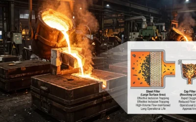
Coarse-first, fine-second — why it works:
-
A looser-grade prefilter takes the large particles first. It absorbs the bulk load (238 L/m² at 186 LMH) before anything reaches the terminal stage
-
The terminal fine filter runs clean — 93–119 L/m² at controlled flux — with no pressure spike and a solid 1-log HCP reduction
-
Multi-layer composite configurations reach 98.52–99.94% efficiency across PM0.5 to PM2.5. A single layer tops out well below that
The pressure drop tradeoff is smaller than you’d expect. A three-layer composite adds just 10 Pa over a single-layer PVDF — going from 29 Pa to 39 Pa. That small jump takes your capture rate from 91.58% to 98.52% on PM1.0. The gain is real. The cost is minor.
One filter working alone will underperform. Split the load, and both filters last longer. Pressure stays stable. Your capture rate stops being the reason castings fail.
Problem #4: Turbulent Flow, Secondary Oxidation, and Gas Entrapment
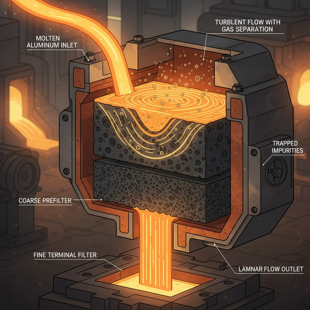
Turbulence doesn’t just move aluminum through a mold — it moves gas into it.
That distinction matters more than most foundry operations recognize. Melt flow turns turbulent, and gas transfer rates climb 30% above low-turbulence baselines. That isn’t a small increase. At production volume, it’s the difference between acceptable porosity and castings you can’t ship.
The mechanism is specific. Vertical turbulence intensity drives gas entrainment. Streamwise turbulence and surface deformation — even at area increases below 0.25% — contribute almost nothing to the problem. Target the wrong variable, and the real cause stays untouched.
What happens during a turbulent pour:
-
Primary vortices form just below the free surface as melt enters the cavity
-
Those vortices break into secondary structures — smaller, faster, harder to predict
-
At Reynolds numbers around 5,000, strong vortex activity creates a jagged turbulent-nonturbulent interface. That interface pulls gas straight into the bulk melt
-
Dissolved oxygen absorption follows predictable kinetics — scaling as 1 − e^(−k_L t) — but once entrained gas spreads through the melt, no downstream filter pulls it back out
Secondary oxidation adds more damage on top of that. Turbulence keeps exposing fresh aluminum surface to atmosphere throughout the fill. Each exposure builds oxide film. Each oxide film becomes a potential inclusion. The filter that catches solid inclusions can’t undo oxide layers already folded into the melt.
The fix works on two levels:
-
Reduce entry velocity before melt contacts the filter. High near-field turbulent intensity is a filter design problem — not just a pour speed problem
-
Select filter geometry that targets vertical turbulence directly — open-area percentage and pore tortuosity both affect how hard the filter breaks up incoming vortex structures
Gas entrapment in aluminum casting mesh filter applications scales in close proportion to flow Reynolds number. Cut turbulence intensity at the source, and gas transfer drops with it.
Problem #5: Backflow Contamination After Mold Filling
The mold is full. Pressure drops. That’s the moment things go wrong.
Most operators treat mold filling as the finish line. It isn’t. The second injection pressure stops, a pressure gap opens between the pouring system and the cavity. Molten aluminum doesn’t stay put in that gap — it reverses direction. Everything the filter caught on the way in — oxides, slag, retained inclusions in risers and gates — gets pulled back into the solidifying metal.
The numbers are bad. Backflow raises inclusion counts by 20–50% in affected zones. In A356 alloy castings, entrained air and inclusions push porosity up 8–12%. Defect rates in wheels and engine blocks climb 15–30%. That’s not slow degradation. That’s a contamination event — and it happens after you think the pour is done.
Low-pressure casting carries the highest exposure:
|
Casting Type |
Backflow Risk |
Key Factor |
|---|---|---|
|
Low-pressure |
High — 3–5x greater |
Controlled pressure drop triggers rapid reversal |
|
Gravity |
Medium |
Slower flow cessation, 10–20% less inclusion carryover |
Low-pressure systems need precise pressure decay curves — 0.2–0.5 bar decay rate. Without that, the pressure drop itself becomes the contamination mechanism.
Three fixes that hold:
-
Maintain post-fill pressure at 0.1–0.3 bar using vacuum assist or blind risers. Remove the pressure differential and you remove the reversal.
-
Position ceramic filters (30–50 PPI) at the gate entrance, upstream of the cavity. Hold a filter-to-gate cross-section ratio of 1.5:1. This keeps ΔP below 0.5 bar and cuts backflow by 70%.
-
Install overflow traps at 5–10% of mold volume. These capture contaminants before they reach the casting zone.
Run through this checklist on every pour:
-
Calculate ΔP so sprue base pressure exceeds cavity pressure by 0.2 bar post-fill
-
Size the filter-to-cavity area ratio at 1:2 to 1:3 — this limits flow reversal velocity to below 0.5 m/s
-
Validate with mold flow simulation. Target: less than 5% backflow volume
NADCA standards set the benchmark at filter ΔP under 1 bar with a pressure hold of 5–10 seconds post-fill. Top designs hit below 2% backflow volume. You can get there — treat post-fill pressure management as part of the filtration system. Don’t leave it as an afterthought.
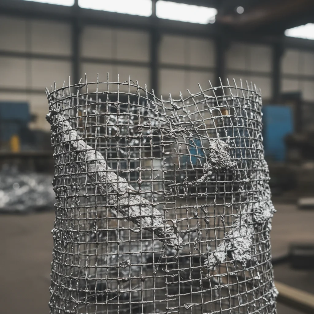
Problem #6: Filter Erosion and Structural Breakdown Under High Heat
Aluminum at 750°C doesn’t flow — it attacks.
Each pour sends superheated melt blasting across filter surfaces at full speed. Heat and friction do the same thing every time: they break things down. Fibers detach. Walls thin out. A filter that holds at the start of a shift won’t hold the same way by the end.
That’s what makes this failure mode dangerous — it’s gradual. Ceramic and fiberglass filters both break down under repeated heat cycles. Fiberglass goes faster. Above 800°C, it loses its shape and strength quickly. Fragments break off and drop into the melt. At that point, you’re not dealing with a filtration problem. You’re dealing with contamination that came from the filter itself.
What to watch for:
-
Surface pitting or visible fiber loss after repeated use
-
Higher fragment counts in finished castings
-
Pressure drops that vary across identical pours
The fix is simple — but not optional:
-
Use high-silica ceramic filters rated for continuous operation above 1,000°C
-
Run filters once and discard them in high-temperature, high-velocity applications
-
Check every filter after use — don’t assume it came through the pour intact
Heat breaks things. It doesn’t wait for a convenient moment to do it.
How to Choose the Right Mesh Filter for Your Aluminum Casting Process
Six problems. Six ways a filter can fail you. But every one of them starts at the same place — the selection decision made before the first pour.
Get that decision right, and you’ve removed most of the risk before metal ever touches the filter. Get it wrong, and no amount of correct installation or process control makes up for it.
Here’s how to make the right call.
Match Aperture Size to the Casting
Aperture size isn’t a preference. It’s a function of what you’re pouring and how much precision the finished part demands.
|
Application |
Aperture Size |
|---|---|
|
Precision castings (pistons, wheels) |
0.8–1.2 mm |
|
General aluminum alloys |
1.0–1.5 mm |
|
Ingots, rods, continuous casting |
1.5–2.5 mm |
Tighter tolerances demand smaller openings. That’s the rule. A piston that fails at the porosity line is a liability. A 0.8 mm aperture filter with carbonized coating keeps inclusion rejection below 3%. It also eliminates bubble and slag content that precision parts can’t survive.
Size the Filter With the Formula
Guessing at filter dimensions is how bypass channels form. Use the formula instead:
F1 = F2 ÷ (A × B)
-
F1 = required filter cross-sectional area
-
F2 = original casting system cross-sectional area
-
A = filter porosity (50–60%)
-
B = filtration rate (60–80%)
Porosity below 50% creates turbulence. Above 60%, fine inclusions slip through. Stay inside the band.
Match Filter Shape to Your Process
Shape isn’t cosmetic. The filter must seat properly and hold up under pour conditions. Shape is what makes that happen.
|
Shape |
Best Use |
|---|---|
|
Flat sheet (cuttable) |
Sprue parting surface; combine with slag bag |
|
Roll cloth (0.93m wide) |
Continuous casting — ingots, rods, strips |
|
Cap / cylinder (resin-coated) |
LPDC applications — cylinder heads, wheels |
Low-pressure die casting needs cap or cylinder shapes. They fit the sprue geometry without gating modifications. Flat sheets used in LPDC leave gaps. Gaps become bypasses.
Confirm Temperature Rating Before You Commit
Standard E-glass fiberglass handles 700–800°C. Its softening point sits near 900°C. That margin looks comfortable — until your pour temperature pushes 750°C with localized hot spots above 800°C. Silica mesh extends the usable range but also softens above 900°C.
The hard limit: nothing above 850°C for standard aluminum filtration. Beyond that, degradation isn’t a risk — it’s a certainty.
Never Cross Metal Systems
One mistake wipes out every correct choice above it.
-
Galvanized or iron wire mesh puts Fe contamination straight into the melt. Fe beyond the critical threshold drops mechanical strength. The affected risers turn into non-remeltable scrap — you can’t recover them.
-
Alkali-free E-glass (SiO₂ at 58%, weight 150–350 g/m², thickness 0.18–0.35 mm) keeps contamination out and stays recyclable after filtration.
-
Leno weave with high-twist yarn holds its shape under aluminum melt pressure. Plain weave loosens under load.
Aluminum filtration is not interchangeable with iron or steel filtration. Check every filter specification before it enters your process.
Step-by-Step Installation Checklist for Maximum Filtration Performance
Thirty percent of filtration systems underperform. Bad filters are rarely the cause. Misaligned cartridges are. That one installation error, documented in WQA research, wipes out close to a third of the performance you paid for — before the first pour even begins.
The checklist below closes that gap.
Before You Touch a Filter
Match your filter to the contaminant profile of your melt. Check inclusion size, temperature range, and flow rate. Then verify housing dimensions to the nearest 1/8 inch. A filter undersized by even a few millimeters opens a bypass channel. Unfiltered melt finds that channel every time.
Check your operating pressure and flow rate against the filter’s rated capacity. A pressure drop over 15 psi points to a sizing problem — not an installation problem. Fix it before you install, not after.
Installation Sequence
1. Prepare the housing
Inspect tracks, clips, and seating surfaces for warping or damage. A bent track breaks the seal before the pour starts.
2. Confirm IN/OUT orientation
A backward filter cuts filtration efficiency by 50%. Mark the direction before you seat the filter.
3. Seat and secure
Press the filter into position with steady force. Run a manual check — zero visible gaps. No exceptions.
4. For dual-stage setups
Mount the coarse prefilter upstream of the fine terminal filter. Order matters here. Flip the sequence and the fine filter overloads right away.
5. Pressurize in stages
Bring pressure up bit by bit. Inspect every joint and fitting as you go. A small pressure drop is normal. A large one points to undersizing or a seating problem.
After Installation
Label each filter position — stage, direction, install date. Record your baseline pressure and flow readings. Performance drift shows up fast, and you’ll know right where to look.
Flush the system before moving to production. This clears fines, removes air, and confirms flow rate matches spec.
Recheck cartridge alignment one final time. That 30% performance loss won’t warn you. It just shows up in your scrap rate.
Measuring Success: How to Know Your Mesh Filter Is Working
Good filtration is invisible. Bad filtration shows up in your scrap bin.
The difference between those two outcomes comes down to measurement — knowing what numbers to track, and what those numbers mean.
Three signals tell you whether your mesh filter in aluminum casting is doing its job:
-
Pressure drop — measure across the filter at your standard flow rates. Any shift from baseline means something changed. Either the filter is loading up, or it’s bypassing. Neither is good.
-
Collection efficiency — calculate as E = 1 − (C_out / C_in), averaged over 120 seconds, repeated three times. Keep your results consistent. A result that swings more than 4% between runs points to a seating or sizing problem — not random variation.
-
Visual condition post-run — color change, deformation, or visible fiber loss are failure warnings. The filter looked wrong. That means it performed wrong.
For pore integrity, the Glass Bead Test is the most reliable field method. It identifies the largest 0.5% of penetrating particles and cuts variability from 47% down to 3%. That’s the gap between guessing and knowing exactly what your filter is doing.
Track these three signals. Document your baseline on day one. Any drift from that baseline is your warning sign — spot it early, before it turns into a casting defect.
Conclusion

Every defective casting tells a story — and the mesh filter is usually where that story went wrong.
The problems covered here aren’t rare edge cases. Wrong filter selection, poor installation, incomplete filtration, turbulent flow — these are everyday realities in aluminum casting operations. They erode yield rates and inflate scrap costs. The root cause stays hidden while the losses pile up.
The fix isn’t complicated. It does require focus. Match your mesh filter to your specific alloy and flow conditions. Install it right, every single time. Then measure what’s happening inside your process — don’t assume clean metal. Verify it.
Got recurring casting defects? Start with your filtration setup. Check that before anything else. Nine times out of ten, that’s where the answer is.
Ready to cut the guesswork? Pull up your current filter specifications. Compare them against the selection criteria outlined above. Something doesn’t align? That’s your next move.
Fix the filter. Fix the casting.