Metal casting defects don’t announce themselves. They hide inside finished parts and wait to cause failures at the worst moment.
Mesh filters are one of the most powerful tools for foundry engineers and production managers using investment casting. They stop defects before they form.
But using mesh filters the right way matters. You need the right filter type, the right placement, and the right pour technique. Get those right, and you get clean, laminar metal flow. Get them wrong, and you’re scrapping the batch.
This guide covers it all — filter selection, installation, post-pour inspection, and troubleshooting. Every detail here is built for real operations running anywhere from 500 to 5,000 parts.
What Are Mesh Filters in Investment Casting (And Why They Matter)
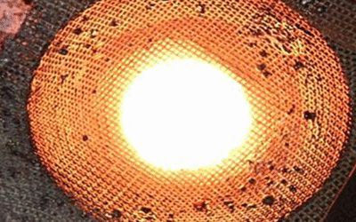
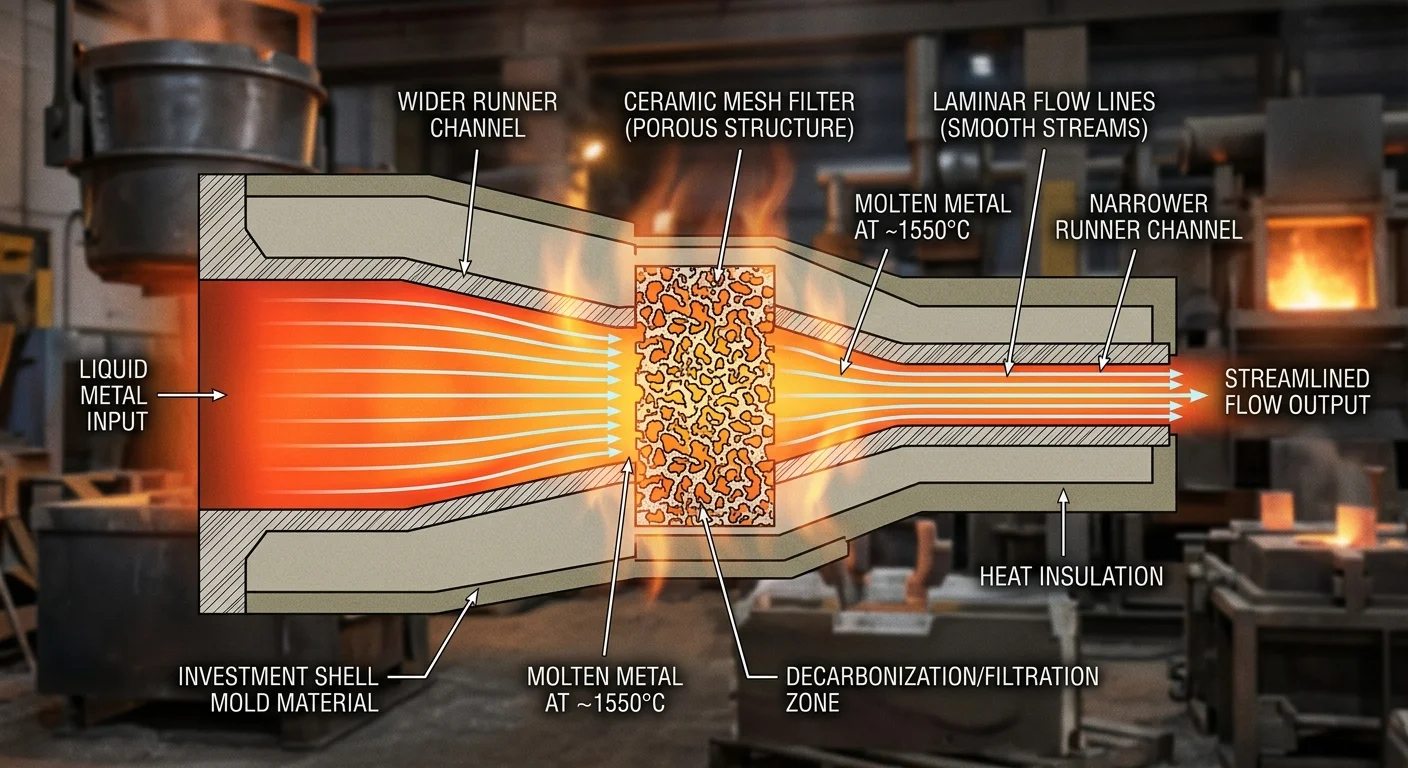
A mesh filter is a woven screen made from high-silica fiberglass — more than 96% SiO₂. It sits inside a gating system and catches everything that doesn’t belong in your final part.
The specs matter here. These filters run 0.50–1.5mm thick, with aperture openings from 0.8×0.8mm up to 2.5×2.5mm. They handle working temperatures up to 1620°C, with a softening point near 1700°C. For aluminum investment casting, that’s more than enough thermal headroom.
In investment casting, the most common form is the cup-shaped (hat-style) filter. It runs 100–120mm in diameter and sits over riser sleeves or pour ports. That shape does two jobs at once. It filters incoming metal and creates a clean break point for riser knock-off after the metal solidifies.
What They Intercept
The targets are clear:
-
Slag and oxide films carried in from the melt
-
Refractory particles shed by ladles or crucibles
-
Non-metallic inclusions — the leading cause of scrapped castings industry-wide
Catching particles is just part of the job. The woven structure also laminarizes metal flow. Turbulent fill erodes shell walls and traps gas. Laminar fill doesn’t. So you get surface finishes down to 32–63 µin Ra and dimensional tolerances held to ±0.003 inches in precision applications. No magic — just physics.
The filter’s working area runs 4–6 times the choked gating section. That ratio keeps fill time stable even as the screen collects debris during the pour.
Types of Mesh Filters Used in Investment Casting
Six filter types. Each one built for a different job. Pick the wrong one and you lose metal, time, and parts.
Here’s what’s available — and what each one does best.
Ceramic Foam Filters
These are the workhorses of investment casting filtration. The open-cell, three-dimensional structure captures inclusions through a depth-capturing mechanism. Particles don’t just get blocked at the surface. They get trapped inside the matrix as metal passes through.
Flow rate starts at 600 mL/sec. That’s the baseline. These filters handle high-temperature alloys well. Made from magnesium-stabilized zirconia, they hold up against extreme thermal shock. For moderate-to-high temperature work, zirconia-mullite or pure alumina variants are the go-to choice. Mullite sits in the middle — high temperatures, intermediate shock resistance.
One trade-off: debris builds up inside the structure. You’ll need to clean them between pours.
Honeycomb Filters
Ceramic foam traps particles deep inside. Honeycomb filters catch them at the surface. Straight channels push metal through fast — flow rate hits 1000 mL/sec, close to double the foam baseline. Debris buildup stays low. No cleaning needed.
Got high-flow pours with low inclusion loads? Honeycomb beats foam every time.
Stainless Steel Mesh Filters
304 and 316 grade stainless steel. Corrosion-resistant, heat-resistant, reusable, and washable.
Custom and Engineered Filters
Complex mold geometry, exotic alloys, or extreme temperatures can push standard filters past their limits. Off-the-shelf options underperform in these situations. Engineered filters fix that.
Placement rule: surface finish and non-fill prevention are the priority? Position filters close to the casting. Cup-style filters placed farther back suit high-flow applications where you can’t afford to restrict throughput.
How to Select the Right Mesh Filter for Your Casting Application
Selection starts with one question: what are you trying to catch?
That answer drives everything — mesh count, material, layer configuration, and whether your filter survives the pour or becomes a restriction problem halfway through the fill.
For aluminum investment casting with surface finish requirements, 1.2 × 1.2 mm openings handle moderate-to-coarse filtration well. High-integrity structural parts need finer openings. Drop down accordingly.
Match the Filter to the Alloy
Material compatibility is not negotiable. The wrong filter material reacts with your melt or breaks down under thermal load.
Apply the 6-Step Selection Process
-
Define the filtration goal — gross particle removal or micro-contaminant capture
-
Match particle size to mesh chart — let the smallest target particle set the ceiling
-
Balance flow rate against pressure drop — coarser mesh flows faster with less restriction. Finer mesh captures more but slows the pour
-
Select material based on alloy chemistry and operating temperature
-
Factor in clogging rate — finer mesh clogs faster. Size up for viscous or high-debris melts
-
Test under real conditions — measure pressure drop and retention efficiency before committing to production volume
Industry Benchmarks by Application
Your industry sets the operating window before you run any numbers:
|
Industry |
Typical Opening Size |
Layer Config |
Priority |
|---|---|---|---|
|
Aerospace |
< 100 μm |
Multi-layer |
Purity and tolerance |
|
Automotive |
250+ μm |
Single-layer |
Flow rate and throughput |
|
Medical |
37–74 μm |
Multi-layer |
Cleanliness, frequent replacement |
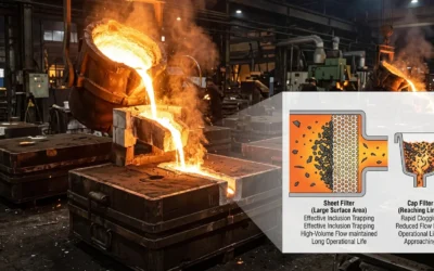
Single-Layer vs. Multi-Layer
Single-layer filters do the job well with low inclusion loads. Clean aluminum automotive pours are the clearest example. Multi-layer setups earn their place when particle sizes vary across a broad range. Also, abrasive particles can damage a fine filtration layer — an outer coarse layer blocks that risk. Titanium and superalloy applications nearly always justify the added layer count.
Pour volume matters too. Large pours need coarser mesh or higher open area to keep flow rate steady. High volume plus wide particle variety? Go with a multi-layer setup. A coarse inlet layer protects the fine capture layer underneath. That combination gives you a more reliable filtration architecture overall.
Step 1 — Positioning and Installing the Filter in the Mold/Gating System
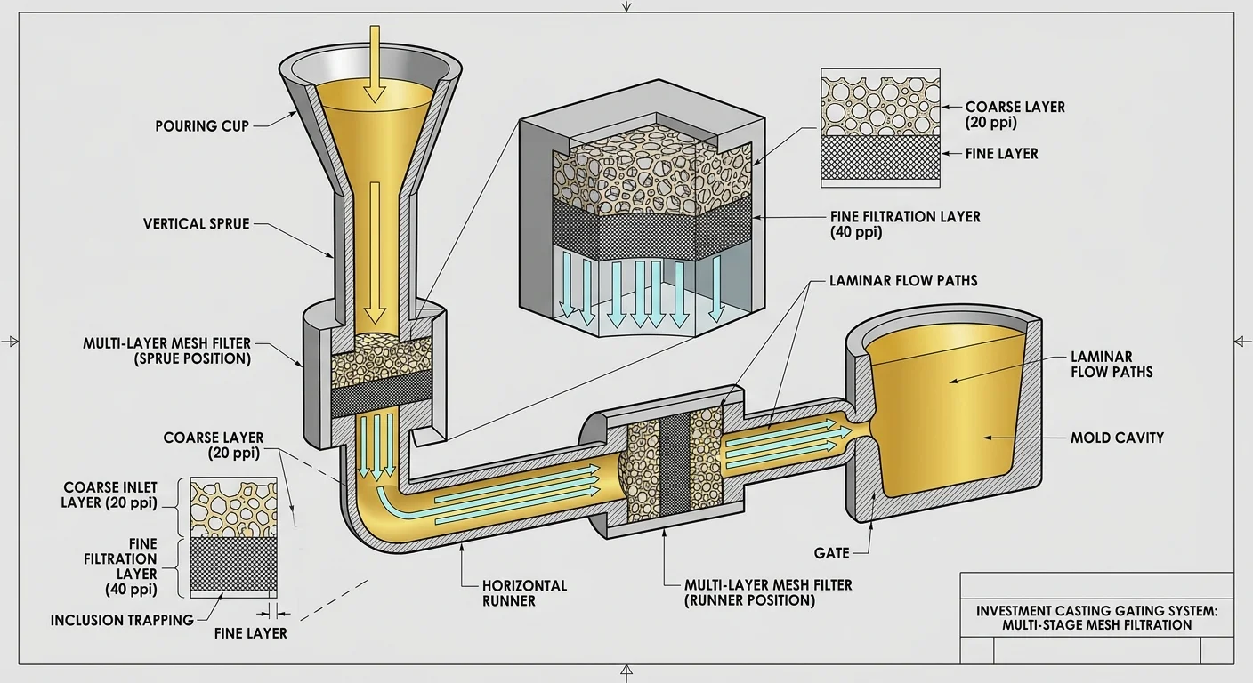
Filter placement is a structural decision. Get it wrong and the filter becomes decoration. Metal bypasses it, turbulence builds up, and the defects you wanted to stop end up in the casting.
Three positions matter in investment casting: the sprue, the runner, and the in-gate. Each sits at a transition point — where metal changes direction, speeds up, or enters a narrower passage. That’s where inclusions build up. That’s where filtration does its real work.
Placement vs. Proximity — Know the Trade-Off
Move the filter closer to the casting (in-gate placement) and inclusion capture goes up. But so does pressure drop. Push it too close and you risk non-fill, early solidification, or trapped air. The filter does its job — and still ruins the part.
Move it farther back — into the runner or sprue — and flow resistance drops. Metal moves faster and with less restriction. For high-flow-rate pours using cup-style filters, that’s the right call. You give up some capture efficiency, but you get a stable, complete fill in return.
No single position works for every situation. Match the placement to your pour weight, alloy viscosity, and part geometry.
Size the Filter Before You Install It
Guessing filter size is how batches get scrapped. Use the formula:
A_filter = W ÷ (n × f_c)
-
W = gross pour weight in kg
-
n = number of filters in the system
-
f_c = filtration capacity in kg/cm² (1–5 kg/cm² depending on filter type)
Real example: a differential housing casting at 23 kg gross weight uses a choke area calculated as CA = 22.6 × W. Run that number, size the filter to match, and it handles the full pour without choking the flow.
Installation — Three Things That Cannot Be Wrong
-
Seating: The filter must contact the mold wall around its entire perimeter. Any gap becomes a bypass channel. Metal always takes the path of least resistance.
-
Alignment: A crooked filter spreads flow unevenly across its face. One section clogs first. The rest of the pour runs through a smaller effective area.
-
Orientation: Set the filter face perpendicular to metal flow. An angled filter raises turbulence and shrinks the working filtration area — the opposite of what you need.
One detail worth noting for molds with a vertical parting line: place the filter past the pouring basin, not at it. By that point, metal has more velocity and a clear direction. The filter engages the flow better there.
Get the seat tight, the alignment true, and the sizing right. Surface finish, dimensional tolerance, and inclusion count all depend on these three basics being correct before the first metal hits the mold.
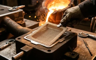
Step 2 — Pouring Molten Metal Through the Filter

The filter is in. Now the pour decides everything.
Three filtration mechanisms kick in the moment metal hits the screen. Surface sieving fires first — particles larger than the pore opening stop at the filter face. Those trapped particles build up fast. They form a cake layer that starts catching finer inclusions the original pore couldn’t grab. Behind that, depth filtration pulls the remaining fine particles into the ceramic matrix. It works through adhesion and winding path capture. The filter gets more effective as the pour goes on. That’s the physics working in your favor — let it run.
Control Your Velocity
Velocity is where most pours go wrong. Keep metal flow below 2.5 m/s. Go past that point and turbulence takes over. It erodes the mold, traps gas, and wipes out every advantage the filter gives you. Hold your pouring cup head height at 70% throughout the pour. That one habit keeps conditions stable from first contact to final fill.
Watch for the warning signs:
-
Splashing at entry — pour speed is too high. Drop it below 2.5 m/s now
-
Back pressure building — pores may be unprimed or PPI is too high. Raise head height, check priming
-
Flow slowing mid-pour — filter cake is overloading. Stop, replace the filter
Match PPI to Your Alloy
PPI selection balances capture efficiency against flow rate. Get it wrong and you’re stuck choosing between inclusions and misruns.
|
PPI |
Application |
Flow Impact |
|---|---|---|
|
10 |
Large iron castings |
Removes coarse slag, minimal restriction |
|
20 |
General automotive iron |
Balanced rate and efficiency |
|
30–40 |
Aluminum cylinder heads |
Finer capture, misrun risk if oversized |
|
50–60 |
Aerospace, high-purity alloys |
Ultra-fine, highest restriction |
One hard limit: monolithic alumina filters capture all particles above 50 µm. Below that, capture becomes partial. Your cleanliness spec demands sub-50 µm capture? A single-stage standard filter won’t do it. You’ll need a different approach.
Temperature ties everything together. Push metal past the filter’s rated limit and thermal shock breaks down the structure mid-pour. Filtration stops. The damage stays hidden until inspection — and by then, it’s too late.
Step 3 — Monitoring Flow and Achieving Laminar Metal Flow
Laminar flow doesn’t happen on its own. You build it — through runner geometry, filter selection, and pour control. Then you watch for signs that it’s holding.
The number that matters most is Reynolds number (Re). Keep Re below 500. At that level, metal moves through the gating system in smooth, organized layers. Go above that threshold and flow breaks into turbulence. Shell walls erode. Gas gets trapped. The filter you installed in Step 1 starts losing the fight.
What Laminar Flow Looks Like on the Shop Floor
You can’t see inside the mold during the pour. But you can read the surface:
-
Steady, unbroken stream at the pouring cup — metal is moving at consistent velocity
-
No splashing or swirling at the sprue entry — turbulence hasn’t taken hold
-
Smooth rise in the mold cavity — laminar fill pushes air out ahead of it, not through it
The stream breaks, pulses, or splatters? Stop. Diagnose the problem before you continue.
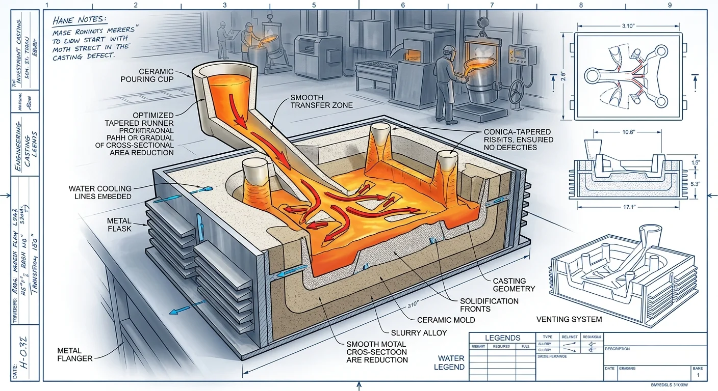
Runner Geometry as a Laminar Flow Tool
Filter placement controls inclusions. Runner cross-section controls velocity. Both matter.
Tapered runners — wider at the sprue, narrower toward the in-gate — hold consistent metal pressure through the fill. Abrupt transitions do the opposite. They speed up flow, spike the Reynolds number, and open the door to turbulence.
Keep runner transitions gradual. Keep cross-sectional area reductions proportional. These two habits do more for laminar flow than almost any other adjustment you can make.
Step 4 — Post-Pour Inspection and Evaluating Filter Performance
The metal has solidified. The mold is cool. Most foundry teams move straight to finishing. That’s where batches get ruined — and no one notices until it’s too late.
Post-pour inspection is where investment casting mesh filters prove their worth. Or it’s where they expose a problem you have to trace back through your entire process.
Start at the filter itself. Cut it out and examine it. Debris distribution across the filter face shows you what happened during the pour.
-
Even cake buildup across the face — filtration worked. Flow stayed laminar and consistent
-
Concentrated debris on one side — the filter was misaligned or metal entered at an angle
-
Clean filter, failed casting — the filter was bypassed. Check your seating from Step 1
Next, move to the castings. Run a visual inspection first, then X-ray on structural or high-tolerance parts. You’re looking for:
-
Surface porosity — caused by turbulent fill
-
Cold shuts or misruns — the filter may have restricted flow beyond capacity
-
Inclusion trails — particles that cleared the filter or came from shell erosion downstream
Using Rejection Rate as a Performance Benchmark
Track your defect rate across batches. A well-specified mesh filter in aluminum investment casting should keep inclusion-related rejections below 1–2% of production volume. Rejections climb above that? The filter is no longer the last line of defense — it’s the first thing you re-evaluate.
Document what you pull off each filter. That debris is data. It tells you whether to size down your mesh openings, add a coarse pre-filter layer, or fix something further upstream.
Common Problems With Mesh Filters (And How to Fix Them)
Filters fail without warning. That’s what makes them dangerous.
By the time you spot something is wrong — rejection rates climbing, surface quality dropping, pressure readings drifting — the problem has been building for several pours. Here’s what goes wrong, and how to stop it before it costs you a batch.
Pressure Drop Is Creeping Up
Particles accumulate. Pores narrow. Flow slows. That sequence happens in every filtration system. Yet foundry teams often read rising pressure drop as a normal operating condition — not a warning sign.
It isn’t normal. Higher back pressure means lower throughput, higher energy consumption, and a filter pushed past its design limits. Let it go too long and one of two things happen: burst pressure gets exceeded, or the bypass valve opens and sends unfiltered metal straight into the casting.
Fix it before it gets there. Run periodic deblinding cycles before pressure climbs into the damage range. Don’t wait for performance to drop in ways you can see.
Pressure Fluctuations Are More Damaging Than High Pressure
This one catches most engineers off guard. A filter rated for a steady 100 psi can break down fast under pressure cycling between 0 and 50 psi. Repeated stress cycles wear down mesh structure faster than a constant load. So design your system with pressure change frequency in mind — not just peak pressure values.
Wrong Mesh Size for the Application
Too coarse and particles pass straight through. Too fine and you’re fighting early blockage and slow fill rates. Both paths lead to the same outcome: scrapped parts.
One more trap worth knowing: nominal vs. absolute micron ratings.
-
Nominal ratings reflect 60% filtration efficiency at the listed size
-
Absolute ratings reach 95%
Mix these up during selection and your filter isn’t doing the job you think it is. Check which rating applies before you order.
Filter Seating and Handling Failures
Filters don’t always arrive damaged — handling damage happens later. Poor technique during cleaning and reinstallation creates wear that builds up over time. A filter that looks fine but sits in the seat wrong will still let metal bypass around its edges.
A few basics that make a real difference:
-
Check seating every time you reinstall
-
Handle filters with care — rough handling creates micro-damage that’s hard to see
-
Log every cleaning cycle so you can track wear patterns over time
These small habits stop the defects that only turn up under X-ray.
Best Practices for High-Volume Investment Casting Operations (500–5,000 Parts)
Scale changes everything. A 50-part trial run is forgiving. At 500 parts, small problems start showing up. At 5,000 parts, every uncontrolled variable turns into a defect pattern you can’t ignore.
Foundries that hold tight yields at high volume don’t guess. They standardize.
Build a Filter Specification Matrix
Stop picking filters job-by-job. Build a matrix organized by product family. Lock it in and stick to it.
Here are the core reference points:
-
IN718 alloy → 30 ppi filter, 0.5–1 L/min flow rate
-
SS316 → 20 ppi filter, 1–2 L/min flow rate
-
Shell thickness: 1–2 mm initial layers, total wall above 10 mm
That kind of standardization cuts batch-to-batch variation by 20–30%. Across a 5,000-part run, that number adds up fast.
Run the ROI Calculation Before You Argue About Filter Cost
Filters cost $0.50–$2 per part. Scrap costs far more.
Run a simple scenario: 1,000 parts, $10 in scrap savings per recovered part, $1 filter cost. That’s a 900% ROI — and that’s before you factor in the 30% drop in rework labor. Add the 10–20% yield gain that filters deliver with the right spec, and the math gets even clearer.
Non-fill defects dropping from 5% to 1% is not a guess. It’s a documented result. Keep fill rate controlled between 1–2 L/min, and you get that outcome.
Conclusion
Mesh filters aren’t a finishing touch — they’re the difference between a casting that ships and one that gets scrapped.
Get the filter selection right. Place it in the right spot in the gating system. Control the pour with purpose. Do all three, and you’re not just removing inclusions — you’re building consistency into every single part. That holds true at 500 pieces or 5,000.
How to use mesh filters in investment casting isn’t a complicated process. But it punishes shortcuts hard. Wrong mesh size, sloppy placement, skipping post-pour inspection — these mistakes eat into your yield rates. And they’re expensive to track down later.
Small filtration adjustments stack up fast. The gains in quality add up — and that’s exactly what separates good foundries from great ones.