Aluminum casting defects from non-metallic inclusions cost you money. Scrapped parts pile up. Quality teams struggle to find answers.
Oxide films leak in automotive parts. Dross particles ruin aerospace castings. Ceramic foam filters can fix these problems at a low cost. But the setup must be right.
Most foundries skip key steps. Others do them wrong. These mistakes turn a good filter into a bottleneck. The right approach gives you smooth castings every time.
This guide covers the full ceramic filter setup process. You’ll learn:
-
How to pick the right pore size for your alloy
-
The pre-heating temperatures that stop thermal shock
-
Priming techniques that catch more inclusions
-
How to measure filtration results with real quality data
Pair ceramic filters with degassing systems. This combo cuts inclusion levels by up to 95%. Plus, rejection rates drop by half.
What Are Inclusions in Aluminum Casting and Why They Matter
Inclusions are unwanted particles in your molten aluminum. These tiny particles and films don’t belong there. They float through the melt and embed in castings. This wrecks the mechanical properties.
The Three Main Culprits
Oxide films form when aluminum meets air. Aluminum oxide bifilms fold into the melt during rough pouring. These thin layers act like internal cracks.
Solid particles come from many sources. Spinels (MgAl₂O₄), magnesia, and carbides wear away from furnace linings. Dirty feedstock brings them in. Poor deoxidation leaves them behind.
Furnace slag enters during ladle changes. CaO-Al₂O₃-SiO2-MgO-Na₂O phases splash from tundish surfaces. Worn refractories add more.
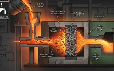
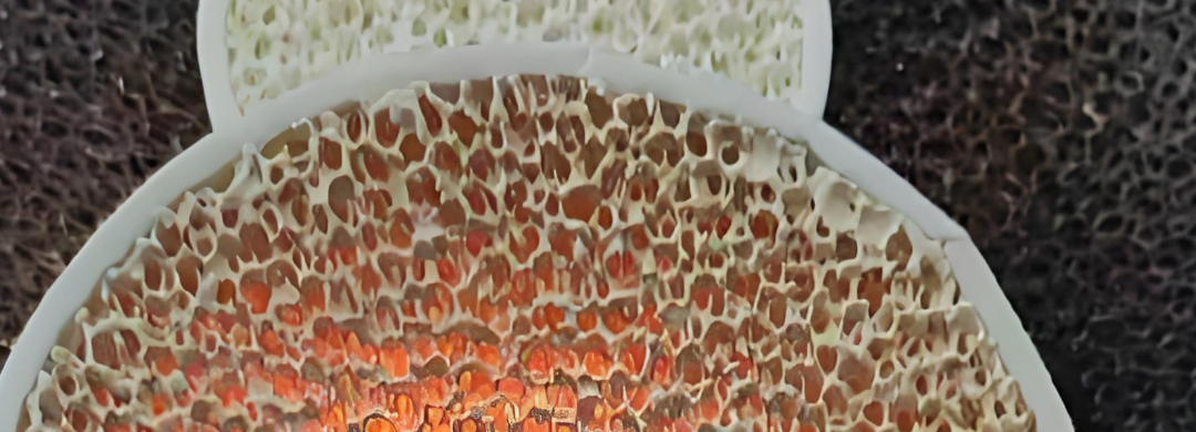
How Ceramic Foam Filters Remove Inclusions – The Filtration Mechanism
Ceramic foam filters don’t work like coffee filters. They don’t just catch big chunks and let everything else through. Six different mechanisms run at once inside that porous block.
The Six-Way Attack on Inclusions
Sieving stops particles bigger than the pore openings. A 25 ppi filter blocks clumps at the inlet face. Simple physics. No particle above 2-3mm gets past.
Cake filtration builds a second barrier. Large inclusions pile up at the entrance. This cake layer traps smaller particles that would slip through alone. The cake thickens. Flow slows. But you get higher capture rates.
Deep bed filtration works inside the foam structure. The melt twists through winding paths. Particles hit ceramic walls. Surface forces pull them in. They stick in corners and tiny pores. Liquid inclusions drop off from entry to exit in a pattern we can measure. SEM and EDX tests on magnesia-stabilized zirconia filters show this. Every caught droplet stays put until tiny pores fill up.
Adsorption adds layer after layer. Small particles coat the inside network. They stick in layers, one on top of another. This happens to all particle types. It keeps going until passages block.
Rectification turns chaos into order. The winding paths force the flow to reverse direction. Rough metal flow becomes smooth flow. This cuts secondary oxidation by 83%. Most inclusions come from rough pouring and air getting mixed in. Smooth flow stops oxide buildup at the source.
Floating separation uses flow resistance as a tool. The filter slows the stream. Slag particles get time to rise. They float in the gating system before metal enters the mold cavity.
Step 1: Select the Right Ceramic Filter Specifications
PPI decides everything. Pores Per Inch measures how many holes fit in one linear inch. Higher PPI means smaller openings. Smaller openings catch tiny particles. But they also slow the metal flow.
Match PPI to Your Alloy and Quality Needs
10 PPI filters have pore sizes between 1000-2000 μm. These suit large iron castings. Surface oxides matter more than fine particles here. Flow stays fast. Filtration stays basic.
10-20 PPI works for general aluminum alloy castings. Most industrial foundries run this range. Pores measure 500-1000 μm. You get decent filtration. Production speed stays good. Scrap rates drop from 12% to under 3% in cast iron parts.
20-30 PPI targets precision work. Pore sizes sit at 300-500 μm. This catches mid-sized slag and dirt in iron castings.
30-40 PPI dominates aluminum casting. This is the industry standard. Pores are small enough to trap oxides and carbides. Flow rates stay strong. Porosity drops by over 50% compared to unfiltered metal. Fatigue life jumps 15-30% in engine cylinder applications.
30-60 PPI serves aviation parts and quality-sensitive extrusion stock. Pores range from 100-300 μm. Filtration is ultra-fine here. Surface finish gets much better.
60-80 PPI offers the highest accuracy. Use this when surface defects cost you contracts. Flow resistance climbs. Production slows. But you remove particles down to 100 μm.
Pick the Right Material for Your Temperature
Alumina (Al₂O₃) handles temperatures up to 1100°C. Porosity runs 70-90%. Strong pull removes particles from aluminum alloy, cast iron, steel, and copper alloy melts. This is your workhorse material.
Silicon Carbide (SiC) tackles higher heat. Same 70-90% porosity. Same alloy range. Use it if alumina can’t take the temperature.
Zirconia survives tough conditions. It costs more but lasts longer in harsh environments.
Cordierite or Mullite honeycomb filters cut flow resistance. Straight holes let metal pour faster. Pick these for thin-walled precision castings. Fill time matters here.
Size the Filter to Your Gating System
Standard sizes run 7″, 9″, 12″, 15″, 17″, 20″, and 23″. Custom cutting works if standard sizes don’t fit your pouring cup or runner. The filter must seal tight. Gaps let unfiltered metal bypass the whole system.
Place the filter where it blocks the full stream. Pouring cups work best. Cross runners work second best. Never put filters where metal can flow around them.
Combine Filters for Better Results
Run coarse filtration first. Then add fine filtration. A 20 PPI ceramic foam filter catches bulk slag. Follow it with a 40 PPI filter or honeycomb ceramic to grab leftover particles. This two-stage setup beats any single filter.
Low-pressure casting needs filters with high porosity. Metal moves slower. You have time for deep filtration. No filling problems. High-pressure casting needs tough filters. Metal hits the ceramic hard. Weak filters crack.
Watch the Pressure Drop
Flow resistance must match your pouring system. Too much blockage causes gaps in filling. Cold shuts form. Misruns waste metal. Calculate the pressure drop across your filter setup. Keep it under the limit. Gravity or pressure must push metal through fast enough.
Unfiltered metal raises scrap rates by 10-20%. Filters cost pennies compared to rejected castings. Pick the highest PPI your system can handle. Don’t create flow problems. You’ll see the difference in ultrasonic testing and tensile strength data.
Step 2: Proper Filter Pre-heating to Prevent Thermal Shock
Cold ceramic meets 700°C molten aluminum. The filter cracks right away. Your $200 filter becomes scrap before metal even flows.
Thermal shock kills ceramic foam filters. Temperature changes too fast. Internal stress builds. Cracks spread. The filter breaks into pieces. Or it develops thin cracks that let unfiltered metal leak straight into your casting.
Step 3: Filter Priming and Wetting Process
Dry ceramic hits molten aluminum. The metal beads up. It rolls across the surface instead of soaking in. Your filter becomes a dam, not a filter.
Wetting decides if your ceramic foam filter works or fails. The ceramic must pull liquid aluminum into its pores. Surface tension fights this. Aluminum wants to stay in droplets. Win that fight before metal flows.
The Pre-Wetting Window
Heat the filter to 600-650°C in your preheat furnace. This temperature opens the ceramic structure. Heat expansion creates tiny gaps. Surface moisture burns off. The ceramic is now ready.
Pour a small amount of molten aluminum over the filter surface 15-30 seconds before main flow starts. This priming shot does three things. It coats the ceramic walls. It fills surface pores. It creates a wet pathway for the bulk metal to follow.
The priming volume matters. Use 2-3% of total pour weight for filters under 12 inches. Bump it to 3-5% for larger filters above 15 inches. A 50 kg casting needs 1-1.5 kg of priming metal for a 10-inch filter.
Step 4: Correct Installation in Filter Box and Runner System
The filter box sits between your ladle and mold cavity. This spot controls whether inclusions get trapped or flow through. Bad installation here throws away all the money you spent on quality ceramic foam filters.
Lock the Filter in Place
The filter must seal against all four walls of the filter box. A 2mm gap lets unfiltered metal skip the entire filtration system. That gap acts as a highway for oxide films and slag particles.
Measure your filter box internal dimensions first. Then pick a filter that fits with maximum 1mm clearance on each side. Tighter is better. Zero gap is best. The filter should wedge into position with light pressure.
Use ceramic fiber gaskets around the edge if gaps exist. Metal pressure compresses these gaskets. They seal the edges as metal flows. Standard gasket thickness runs 3-6mm. Pick the size that fills your gap.
Never force an oversized filter into a small box. The ceramic will crack. You’ll pour metal through broken pieces instead of a working filter.
Position Matters in the Gating System
Place the filter in the pouring basin or sprue base for gravity casting. Metal hits the filter right after leaving the ladle. Filtration at this stage stops inclusions before they travel through runners and gates. This gives you the cleanest metal possible.
Low-pressure and tilt-pour systems need a different setup. Install the filter in the horizontal runner between sprue and gate. Metal slows down in this section. Slower flow improves filtration. The filter has time to catch particles.
Avoid putting filters at the gate entrance. Back pressure builds there. Metal turbulence goes up. The filter can shift or crack from pressure spikes during rapid filling.
Step 5: Pouring Technique and Flow Control
Metal speed at the filter face changes everything. Pour too fast? You get turbulence. The filter shifts. Unfiltered metal splashes over the top. Pour too slow? The metal starts to freeze before the mold fills.
Control the Stream Velocity
Aim for a linear flow rate of 0.3-0.8 m/s through the ceramic foam filter. This range gives you maximum filtering power. Plus, it won’t damage the ceramic structure. Metal moving faster than 1.0 m/s wears away the foam walls. Bits break off. These bits then dirty your casting.
Calculate flow rate by dividing pour weight by time and filter area. A 50 kg casting through a 12-inch (305mm) filter should take 45-75 seconds. Faster than 35 seconds? You’re pushing too hard. Slower than 90 seconds? The metal cools too much.
Use a bottom-pour ladle with slide gate control for steady flow. Teapot ladles cause speed spikes. The stream speeds up and slows down as you tilt. Each change stirs up oxide films. Slide gates give you constant pressure. The metal flows smooth from start to finish.
Keep the Filter Submerged
Metal level in the filter box must stay 30-50mm above the filter surface during the entire pour. This pressure pushes metal through the foam. Drop below 20mm? Air gets sucked in. The filter stops working. Surface rust shoots up.
Watch for spinning metal in the pouring basin. Swirling metal pulls air down into the filter. Add baffles or step designs to break the spin. Flow straight into the filter. This stops the problem.
Avoid Temperature Loss During Pour
Metal entering the filter should stay within ±10°C of ladle temperature. Every degree of cooling makes the metal thicker. Flow gets harder. Back pressure builds. Cold spots form in the casting.
Preheat your ladle to 400-500°C before filling. This cuts heat loss during transfer. Wrap the filter box walls with ceramic fiber blankets. This keeps metal fluid as it passes through the filter.
Long pour times need higher starting temps. A 3-minute fill needs metal 20-30°C hotter than a 1-minute fill. Calculate cooling rate for your system. Add that number to your minimum casting temperature. You now have your target ladle temperature.
Combining Ceramic Filters with Other Purification Methods
No single purification step removes every inclusion type. Hydrogen hides in solution. Fine particles slip past degassing bubbles. Oxide films form during transfer even after filtration. Stack methods to hit each contamination source.
The Triple-Strike Approach That Cuts Scrap by 40%
Flux treatment strips alkali metals first. Chloride and fluoride salts adsorb sodium and lithium from the melt. The Mixal process with 3-50% chlorine content cuts sodium by 87% and lithium by 95%. But flux creates harmful gases. It can become a new inclusion source. Skip this step for aerospace work.
Rotary degassing follows next. The rotor spins above 1000 rpm. It injects argon or nitrogen through the melt. Bubbles float hydrogen and large inclusions to the surface. Hydrogen removal works well here. Fine inclusion removal stays under 50%. Bubble size control is too rough for particles under 60 μm.
Ceramic foam filtration finishes the job. The filter sits between the degassing unit and casting equipment. It catches what degassing missed. This three-step sequence drops overall inclusion concentration by 79%. Particle sizes narrow to 30-60 μm. The filter shows 68% efficiency for inclusions in the 20-29 μm range.
Foundries running this combo see scrap rates fall 15-40% with correct alumina ceramic foam filter setup.
Two-Stage Filtration Beats Any Single Filter
Run coarse filtration before fine filtration. A 10-20 ppi ceramic filter placed after SNIF degassing blocks bulk slag and large oxides. Then add a metallics cartridge filter or 30-50 ppi ceramic foam filter as the second stage.
The first filter builds a filter cake of trapped particles. This cake improves capture ability. Small inclusions stick to the deposited layer instead of passing through. The second filter grabs particles the first stage missed.
Post-treatment N20-N80 values drop to 4.9-0.07 k/kg with this SNIF + CFF + MCF sequence. Inclusions above 60 μm disappear.
Launder Degassers and Filter Placement
Install the online degassing device between your holding furnace and casting line. The launder-type degasser drops temperature by 10-35°C as metal flows through. Preheat your ceramic filter to ≥460°C to match this cooled metal temperature.
The degasser processes 200-600 kg/min with nitrogen flushing through a corundum ball filter. Hydrogen removal rates hit 30-40%. The ceramic foam filter installed downstream handles inclusion removal. This split of tasks works better than asking one device to do both jobs.
Match Filter PPI to Your Degassing System
High-pressure die casting needs 10-20 ppi filters after degassing. Metal moves too fast for finer mesh. Gravity casting systems work with 20-30 ppi. Aerospace work demands 30-50 ppi for ultra-fine filtration after gas purification.
Flow rate through the filter should stay at 1-2 kg/cm²·min regardless of PPI choice. Adjust filter size to maintain this rate. A 12 holes/cm filter at 50mm thickness removes 80% of debris above 100 μm. This setup cut aluminum foil end breakage by 44% in rolling mill trials.
High-silicon aluminum flows well. You can push to higher PPI counts. High-magnesium aluminum runs thick. Drop to lower PPI or metal won’t flow through.
Watch for Filter Bypass
Ceramic fiber pads must seal the gap between filter and housing. Even a 2mm opening lets unfiltered metal skip around your entire purification system. That gap wastes your degassing investment and your filter cost.
Replace filters when pressure difference increases or pouring speed drops. The filter cake blocks too much flow. Trying to push metal through a clogged filter creates turbulence. This turbulence generates new oxide films. You end up adding inclusions instead of removing them.
Key Filter Specifications and Selection Chart
Numbers tell you which filter works. Charts show you where it fails. Most foundries guess at filter specs and wonder why rejection rates stay high.
The PPI-to-Pore Size Conversion You Need
PPI doesn’t tell you pore diameter. A 30 ppi filter doesn’t have 30-micron holes. The actual opening size runs much larger. Here’s what you get:
-
10 PPI: 1000-2000 μm openings
-
20 PPI: 500-1000 μm openings
-
30 PPI: 300-500 μm openings
-
40 PPI: 200-300 μm openings
-
50 PPI: 150-250 μm openings
-
60 PPI: 100-200 μm openings
Match these numbers to your target particle size. Got 150 μm inclusions? A 20 ppi filter lets particles pass right through.
Filter Effective Area Drives Flow Capacity
Diameter affects throughput speed. A small filter slows your pour rate. An oversized filter costs more but doesn’t improve results.
Standard metric sizes:
-
7″ (178mm): 248 cm² effective area
-
12″ (305mm): 730 cm² effective area
-
17″ (432mm): 1465 cm² effective area
-
23″ (584mm): 2678 cm² effective area
Target flow rate sits at 1-2 kg/cm²·min for aluminum. A 50 kg casting in 60 seconds needs minimum 417 cm² filter area. Round up to the next standard size for safety margin.
Troubleshooting Common Filtration Problems
Filter pressure spikes during your aluminum pour. Metal backs up in the runner. The casting comes out with more defects than before you installed the filter. Something broke in your filtration system.
Filter Cracking From Thermal Shock
Cracks show up as bright metal lines across the filter face after pouring. The ceramic split from temperature stress. You either skipped preheat or the gap between preheat temp and pour temp went past 50°C.
Use a pyrometer to measure your preheat temperature. Don’t guess. A filter that feels warm isn’t at 600°C. Heat it to within 50°C of your metal temperature. Let it soak for 30 minutes at minimum. Large 23-inch filters need 45-60 minutes to heat all the way through.
Check for cold spots in your preheat furnace. One corner stays cool while the rest heats up? The filter cracks where cold meets hot during pouring.
Metal Bypassing Around Filter Edges
Bright, clean metal shows up in your casting next to dark filtered areas. Unfiltered aluminum found a gap between the filter and box walls. A 2mm opening throws away your filtration investment.
Pull the filter after each pour. Look for metal frozen against the box walls instead of going through ceramic. This proves bypass flow. Measure your filter box internal size. Compare it to filter size. You need maximum 1mm clearance per side.
Seal gaps with ceramic fiber gaskets. Use 3-6mm thick gaskets around all four edges. Metal pressure crushes the gasket during pouring. This creates a temporary seal. Replace gaskets every 5-10 pours as they compress and won’t spring back.
Clogged Filters Slow Your Pour Rate
Pour time doubles from one casting to the next using the same filter. Back pressure builds in the pouring basin. Metal starts to freeze before the mold fills. Your filter cake grew too thick.
Track pour time for each casting. Time increases by 30% above baseline? The filter is done. A fresh 30 ppi filter pours 50 kg in 60 seconds. After 15 castings, the same pour takes 80-90 seconds. Replace it.
Don’t try to push metal through a clogged filter faster. High pressure breaks the filter or creates turbulence. Both actions add new oxide films to your clean metal.
Poor Wetting Creates Flow Blockage
Metal beads up on the filter surface instead of soaking in. Flow stops or crawls at 20% of normal speed. The ceramic never wetted right.
This happens two ways: preheat temperature drops below 500°C or you skip the priming pour. The ceramic stays water-repellent. Aluminum can’t get into the tiny holes.
Pour a 2-3% priming shot of molten metal over the casting filter 15-30 seconds before main flow. Watch the metal spread and darken the ceramic. It stays bright and pooled? Your preheat temp is too low. Boost preheat by 50°C and try again.
Conclusion
Cutting inclusions in aluminum casting with ceramic filters isn’t complex—but you need careful steps. The five-step process we’ve outlined gives you real quality gains: fewer defects, better metal properties, and lower scrap rates. From picking the right pore size to nailing your pour technique, each step counts.
The big shift comes when filtration becomes a precision task, not an add-on. Pre-heating counts. Priming counts. Installation position counts. Each part adds up to either top-quality castings or costly rework.