Steel casting defects from impurities and inclusions cost manufacturers thousands of dollars. Rejected parts and wasted materials add up fast. Ceramic filters solve this problem—they clean molten metal and cut scrap rates.
Using ceramic filters in steel casting takes more than just placing one in your gating system. You need to know which filter to pick. Placement matters too. Many foundries miss key process control steps.
Got porosity issues? Dealing with inclusion defects? Or maybe you want better filtration results. This guide gives you six proven steps to improve casting quality.
You’ll learn practical installation methods. Common mistakes that hurt filter performance? We show you how to skip them. Plus, you get the same optimization strategies top foundries use to keep rejection rates under 2%.
Proper ceramic filter setup makes the difference. It turns acceptable castings into exceptional ones.
Understanding Ceramic Filter Basics for Steel Casting
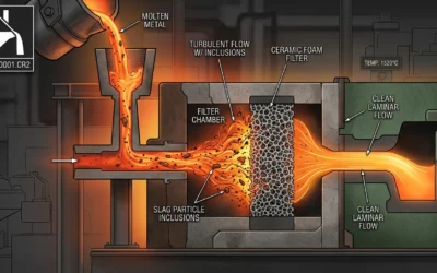
Ceramic foam filters trap dirt through connected passages inside the filter. Molten steel flows around ceramic bars. Non-metallic bits stick and build up there. Advanced ceramic foam filters remove over 95% of non-metallic inclusions from your molten metal stream.
The filter does four key jobs at once:
-
Capturing – Traps slag, oxides, and other dirt
-
Flowing – Keeps metal delivery rates steady into your mold
-
Containing – Stays strong under heat shock and metal pressure
-
Smoothing – Turns rough flow into smooth patterns
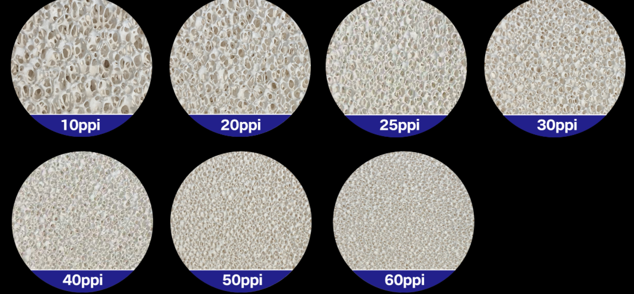
PPI Rating: Your Filter Selection Starting Point
The pores per inch (PPI) measurement tells you which filter fits your steel grade. Think of PPI as the filter’s mesh density. Higher PPI numbers mean smaller pore openings. This gives finer filtration.
For Cr-Mo steel casting, foundries use 10 PPI filters as the industry standard. Different steel types need different PPI ratings. Carbon steel uses 10-20 PPI. Stainless steel grades often need 20-30 PPI. This captures finer oxide particles.
Beyond Traditional Foam Filters
3D-printed ceramic filters are the latest filtration technology. These filters deliver repeatable metal flow rates. Conventional foam filters can’t match this. Their random passage structures make flow rates inconsistent. Current production tests run across 8 foundries in North America and Europe. Results show much lower flow variation compared to traditional foam options.
Standard 50mm × 50mm filter dimensions handle castings with total weights around 15 kg (including feeders and gating channels). Pick your filter material based on your alloy chemistry. Pouring temperature matters too.
Step 1: Picking the Right Ceramic Filter for Steel Casting
Your filter choice shapes casting quality, scrap rates, and costs. Three key factors matter: filter material, pore density, and how well it handles your steel grade’s temperature.
Material Selection: Zirconia Works Best for Steel
Zirconia-based filters lead the steel casting market. They handle thermal shock better than other types. STELEX ZR ULTRA filters from Foseco are built for steel work. These filters keep their capacity and flow steady. They break down less, so you get fewer filter defects.
Low-carbon steel brings its own problems. Metal flowing through your gating system can pick up oxygen again. This creates inclusions. STELEX PrO carbon-bonded filters fix this issue. Place them at the ingate. They catch fresh inclusions that downsprue filters miss.
Zirconia-Mullite and pure Alumina filters handle moderate to high temperatures well. Pick your filter based on casting temperature and alloy type.
Pore Density and How It Filters
The 10–30 PPI range fits most steel casting jobs. Two things determine your pore size: how much contamination sits in your molten metal and pouring temperature.
Ceramic foam filters trap particles as small as 0.5 mm. Good filters pull out up to 80% of inclusions from steel. One foundry switched to zirconia-based filters. Results: 50%–70% less upgrading time and 50%–70% less welding material used.
Step 2: Finding the Best Filter Placement Position
Filter location controls how your ceramic filter catches inclusions. It also manages metal flow. The position decides if contaminants get trapped or flow into your mold cavity. Most foundries place filters in three spots: the sprue base, horizontal runner, or just before the ingate.
Horizontal Runner Placement: The Industry Standard
Horizontal runner installation gives the best filtration for medium to large steel castings. Place your ceramic filter flat in the runner section between the sprue and gates. This spot offers three benefits:
-
Metal velocity drops as it enters the wider runner cross-section
-
Turbulence decreases before metal reaches the filter surface
-
Multiple gates can benefit from a single filter placement
The calmer flow makes filters work better. Trapped inclusions spread across the filter face instead of piling up in one spot. One Chinese steel foundry tested horizontal runner placement on 50kg carbon steel castings. They cut inclusion-related scrap from 12% down to 3%. All they did was move filters from the sprue base to the runner.
Sprue Base Installation for High-Flow Applications
Heavy sections or high pouring rates? Place filters at the sprue-runner junction. This position works for investment castings that need fast mold filling. The filter catches inclusions right after metal enters the gating system.
Watch out for one problem: metal hits the filter with higher velocity and temperature. You need thicker filter sections (75mm minimum) to prevent breakthrough. Some foundries add a small well below the sprue. This buffer zone protects the filter from direct metal impact.
Ingate Positioning for Multi-Cavity Molds
Ingate filter placement fits molds with multiple cavities or complex branching systems. Install individual filters at each gate entrance. This setup stops reoxidation products that form in the runner system. Each casting gets its own filtration checkpoint.
The downside? Higher material costs. You need one filter per cavity instead of sharing one filter across multiple gates. Calculate your economics: if inclusion defects cost more than extra filters, ingate placement pays off.
Step 3: Pre-Installation Inspection and Preparation
Damaged filters cause defects that ruin entire batches. A cracked filter lets molten steel skip the filtration step. Inclusions flow straight into your mold cavity. One missed chip wastes hours of work and metal.
Visual Inspection Protocol
Check every filter surface before you install it. Look for cracks, chips, or corner damage. Run your gloved hand across all faces. Surface breaks feel like rough edges or dents. See any damage? Reject that filter. No exceptions.
Check for warping too. Place the filter on a flat surface. Gaps between the filter base and table show warping. Warped filters create uneven metal flow. Inclusion pockets build up on one side.
Spec Check
Match your filter specs to what the casting needs. Confirm PPI rating, dimensions, and material type against your work order. A 20 PPI filter fails in a 10 PPI application. The finer pores clog fast. Metal flow stops mid-pour.
Measure filter thickness with calipers. Standard 50mm × 50mm filters should measure within ±2mm tolerance. Undersized filters leave gaps in your runner system.
Handling and Storage Tips
Keep filters in sealed packaging until you install them. Moisture weakens the ceramic structure. Store filters in dry areas away from foundry floor dust.
Handle filters with clean, dry gloves. Skin oils contaminate pore surfaces. This cuts filtration efficiency by up to 15%.
Step 4: Secure Installation Techniques
Filter movement during metal pouring creates gaps. These gaps let dirt and debris bypass your filtration system. Your ceramic filter must stay locked in position. It needs to hold firm from first metal contact through complete mold filling. Three installation methods work best in steel foundries: compression fitting, adhesive bonding, and integrated filter boxes.
Compression Fit Installation for Runner Systems
Cut your runner channel a bit smaller than the filter size. Aim for 1-2mm tighter fit on all sides. The filter wedges into place. Sand mold pressure holds it steady during pouring.
Pack molding sand tight around filter edges. Leave no empty spaces. Loose sand shifts as metal flows. This opens bypass paths along filter edges. One German foundry tracked results: filters with gaps smaller than 0.5mm showed 15% better dirt removal compared to loose-fit setups.
Test your fit before closing the mold. The filter should resist gentle pushing. Too tight? The filter cracks during mold setup. Too loose? Metal takes the easy path around your filter instead of through it.
Adhesive Method for High-Temperature Use
Alumina-based ceramic cement bonds filters to mold surfaces in investment casting. Put thin cement beads around the filter edge. Press the filter into your pre-formed cavity. The bond sets during mold preheating at 200-300°C.
This method stops filter floating in horizontal runner setups. Rising forces from molten steel can lift loose filters. Bonded filters stay anchored no matter how rough the metal flows.
Don’t use too much adhesive. Thick cement beads block pore openings along filter edges. This cuts your effective filtration area by up to 20%.
Step 5: Metal Pouring Process Control
Temperature and speed during metal pouring decide if your ceramic filter works or fails. Too much heat damages the filter structure. Fast pouring overloads the filter surface with debris. Both problems create defects that get into your casting.
Monitor Critical Temperature Parameters
Pouring temperature must stay within your alloy’s spec range. For steel casting, this runs 50-80°C above liquidus temperature. Higher temps cut filter life by 30-40%. Extreme heat breaks down the ceramic structure faster.
Track mold temperature before each pour. Cold molds cause metal to solidify too soon at the filter face. This blocks pore openings. One foundry tracked their data: molds below 150°C showed 25% more filter clogging compared to preheated setups.
Use thermocouples and data logging systems to record metal and mold temperatures. Set alarm limits for conditions outside spec. Real-time monitoring catches problems before bad metal reaches your filter.
Control Pouring Speed and Height
Automated pouring systems give you the most consistent results. Robots maintain steady flow rates that manual ladles can’t match. This cuts impact force on your ceramic filter surface. Even distribution stops inclusion buildup in one spot.
Manual pouring needs strict operator discipline. Train your team on standard pouring heights and speeds. Use visual guides or fixtures to keep ladle position consistent. Height changes of just 10cm alter metal velocity enough to hurt filtration performance.
Use Statistical Process Control
Control charts track key pouring variables across multiple heats. Plot metal temperature, fill time, and filter condition after each pour. Spot deviations before defect patterns show up and scrap rates climb.
Document filter breakthrough incidents. Note the exact conditions: temperature, pouring speed, metal cleanliness level. This data builds your reaction plan for future pours.
Step 6: Post-Pouring Inspection and Quality Verification
Steel hides filtration problems once it hardens. Your ceramic filter could fail mid-pour. You won’t see visible signs during casting. Post-pouring checks show what worked. They show what didn’t. Plus, you build data to improve future filter performance.
Filter Physical Inspection After Cooldown
Wait until the casting cools below 200°C. Then remove the used ceramic filter. Check the filter surface for trapped inclusion patterns. Heavy buildup on one side? That shows uneven metal flow. This points to gating system problems, not filter failure.
Look for filter breakthrough signs:
– Cracks through the filter body
– Eroded sections where ceramic washed away
– Dark marks showing metal passed through damaged areas
Take photos of damaged filters. Include scale references. Compare images from multiple pours. You’ll spot patterns. These point to temperature issues, installation errors, or wrong PPI choice.
Casting Quality Verification Methods
Cut test samples from non-critical sections near the filter. Use metal examination to count inclusions. Grind, polish, and etch samples per ASTM E45 standards. Compare inclusion counts between filtered and unfiltered tests.
Ultrasonic testing (UT) finds internal defects. Parts stay intact. Scan critical load-bearing sections. Porosity and inclusion clusters disrupt the signal. Mark where defects sit relative to filter placement.
Track mechanical property results from tensile test bars. Cast these alongside production parts. Ceramic filters boost tensile strength by 8-12% in carbon steel castings. Fewer inclusions mean fewer stress points.
Documentation and Continuous Improvement
Record filter performance data in your quality system:
– Metal temperature at pour start and finish
– Total pour time and metal weight filtered
– Filter condition rating (1-5 scale)
– Casting acceptance rate for the heat
Build a filter performance database. Link installation variables to casting outcomes. Stats show which factors drive quality gains. Adjust your ceramic filter specs based on real production data. Don’t rely on supplier advice alone.
Measurable Benefits and Performance Data
Numbers show the real story of ceramic filter performance in steel casting. Foundries that track filtration see clear gains in quality, output, and costs.
Defect Reduction and Quality Metrics
Inclusion removal efficiency ranks as the top benefit. Zirconia-based ceramic filters catch 80-95% of non-metallic particles in molten steel. Testing labs measure this with ASTM E45 inclusion rating standards. Castings filtered through proper ceramic systems drop from Severity Level 2.5 to Level 0.5 on the Thin Series scale.
Surface finish quality improves by 30-40% in Ra (roughness average) measurements. One European steel foundry saw Ra values drop from 12.5μm to 8.1μm after switching to 20 PPI ceramic filters. Cleaner metal means less grinding time on finished castings.
Mechanical properties become more consistent. Tensile strength variation drops from ±15% to ±6% across production batches. Elongation values stay stable within 2-3% ranges. Unfiltered pours swing 8-10%.
Production Cost Savings
Scrap rates fall 50-70% with proper ceramic filter installation. A medium-sized facility casting 500 tons per month reported £175,000 in annual savings. Their inclusion-related scrap dropped from 12% to 3.8% within six months.
Machining tool life extends 35-50% on filtered castings. Cutting inserts last through more parts. Fewer hard inclusions contact tool edges. One job shop calculated £28,000 in annual savings on carbide tooling alone.
Welding repair costs drop fast. Foundries spend 60-75% less on defect correction labor after adding ceramic filters. Repair hours per ton decrease from 4.2 hours to 1.1 hours on average.
Yield and Throughput Improvements
Metal yield ratios climb 8-12% with better filtration. Less metal gets trapped in gating systems. Filters enable simpler runner designs. Foundries report shipping 485kg of good castings from each 500kg heat. Their previous average was 435kg.
Casting temperature can drop 30-50°C without losing quality. Cleaner metal flows better at lower superheat levels. This cuts energy costs by £15-22 per ton of steel poured.
First-pass acceptance rates jump from 76% to 94% in documented case studies. Fewer castings need rework or scrapping. This speeds delivery times and frees up furnace capacity.
Troubleshooting Common Issues
Ceramic filters fail. This happens when foundries miss key installation steps or lose process control. Metal bypasses the filter. Inclusions get into your casting. The filter breaks down mid-pour. Each problem has specific causes and fixes.
Filter Breakthrough During Pouring
Breakthrough happens when molten steel burns through your ceramic filter structure. You’ll see metal flowing straight into the mold without filtration. Dark erosion marks appear on the filter surface after cooldown.
Three factors cause breakthrough:
-
High pouring temperature (80°C+ above liquidus) destroys ceramic bonds
-
Thin filter sections can’t handle metal pressure and heat
-
Damaged filters with existing cracks fail under thermal shock
Fix this. Measure metal temperature with calibrated thermocouples before each pour. Keep superheat within 50-70°C above liquidus. Use minimum 50mm thick filters for steel casting. Reject any filter showing cracks during pre-installation inspection.
Uneven Inclusion Distribution
Heavy buildup on one side of your used filter signals flow problems in the gating system. Metal velocity stays too high on one side. Inclusions pile up instead of spreading across the full filter face.
This pattern shows up in these cases:
-
Runner cross-sections are too small for your metal flow rate
-
Sharp corners create turbulent zones before the filter
-
Filter placement sits off-center in the runner channel
Correct this. Widen your runner sections to slow metal velocity. Add radius curves at runner junctions. Center your ceramic filter exact in the horizontal runner. Use compression fit installation to prevent shifting during mold closure.
Premature Filter Clogging
Filters clog before pouring completes. This happens when inclusion levels exceed filter capacity. Metal flow stops mid-pour. You get incomplete castings or cold shuts.
Common causes include:
-
Dirty furnace practice puts excess slag into your ladle
-
Wrong PPI rating – too fine for your contamination level
-
Undersized filters can’t handle total metal volume
Solve this. Improve metal cleanliness before pouring. Skim slag during ladle transfer. Switch to lower PPI ratings (10-15 PPI instead of 20-30 PPI) for contaminated melts. Use multiple filters in series for large castings over 100kg. Calculate filter area based on 1 square inch per 10 pounds of filtered metal as a starting point.
Inconsistent Filtration Results Between Heats
Performance varies batch-to-batch. This occurs even with identical filter specs and procedures. One heat produces clean castings. The next shows inclusion defects.
Track these variables in your quality records:
-
Actual pouring temperature for each heat
-
Metal cleanliness rating before filtration
-
Filter supplier and manufacturing lot number
-
Mold preheat temperature readings
Build a database linking these inputs to casting acceptance rates. Stats show which factors drive quality swings. Adjust your ceramic filter selection and process controls based on real production data instead of supplier recommendations alone.
Advanced Optimization Strategies
Top foundries mix ceramic filters with automated controls and data systems. This pushes performance past standard results. These methods target three areas: process automation, predictive maintenance, and multi-stage filter setups.
Automated Pouring Systems Integration
Robotic pouring removes human error. This error causes 40% of filter failures. Machine learning predicts the best pouring rates based on alloy type, mold temperature, and filter PPI rating. One Midwest steel foundry installed automated ladle controls. These controls adjust flow speed in real-time. Results: filter breakthrough incidents dropped 78%. Inclusion defect rates fell from 4.2% to 0.9%.
Position sensors track ladle height within ±5mm accuracy. Temperature monitors trigger alarms when metal gets too hot. This precision cuts wasted filter capacity by 35%. Every filter works at full power instead of failing from heat damage.
Conclusion
Master how to use ceramic filters in steel casting. This transforms your foundry’s output from acceptable to exceptional. Follow the six-step process—from picking the right filter specs to checking results after pouring. You’re not just removing impurities. You’re investing in better metal quality. This means fewer defects, lower machining costs, and happier customers.
The performance data proves it: foundries using proper ceramic filter techniques see up to 85% fewer non-metallic inclusions. Surface finish quality improves significantly too. Are you troubleshooting existing problems? Or optimizing your current processes with better preheating and flow rate strategies? These principles give you a roadmap to consistent, repeatable results.
Ready to elevate your steel casting quality? Start with a full audit of your current filtration process. Use the inspection checklist provided. Document your baseline defect rates. Implement these proven techniques step by step. Measure the improvements. Your next heat could mark the beginning of a new quality standard in your operation—one filtered pour at a time.