Scrap rates, porosity defects, slag inclusions — you’ve seen how fast a bad pour can wreck an otherwise solid production run. The fix isn’t always about tweaking your alloy or adjusting your furnace temperature. Sometimes, it comes down to something as simple as a ceramic filter sitting in your gating system.
Using ceramic filters in sand casting the right way — the right type, the right placement, the right pour — is what separates clean, consistent castings from expensive rework. This guide walks you through every practical step. You’ll also see the mistakes most foundries make and how to avoid them.
What Are Ceramic Filters and Why Sand Casting Needs Them
Ceramic filters do exactly what the name suggests — yet most foundries don’t fully grasp what they do inside a mold.
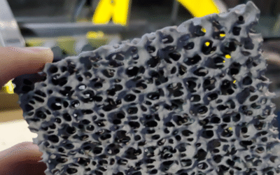
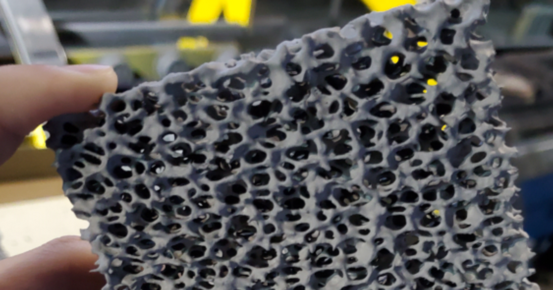
At their core, ceramic filters are open-pore foam structures made from materials like alumina or zirconia. That porous structure isn’t just for show. It builds a deep-bed filtration network. As molten metal passes through, it traps nonmetallic inclusions, slag particles, and oxides — catching them through interception, impaction, and adsorption all at once.
But filtration is only half the story.
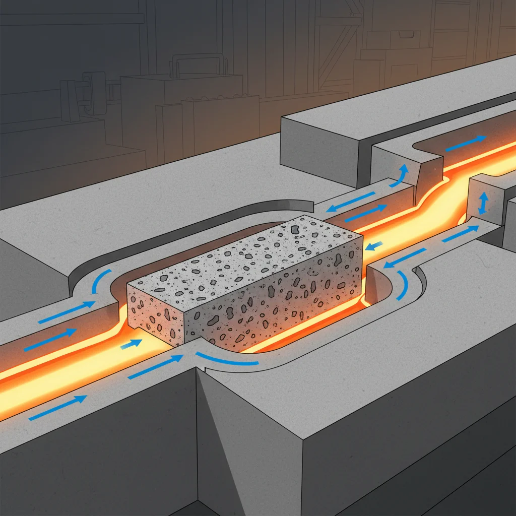
The other half is flow control. Liquid metal hits the ceramic filter, and turbulence drops fast. What enters your mold cavity becomes something much closer to laminar flow — smooth, directional, and controlled. Less turbulence means less air gets pulled in. Fewer oxide films form mid-pour. Your mold fills in a steady, uniform way instead of a chaotic one.
Here’s what happens when sand casting runs without them:
-
Porosity and gas bubbles form as turbulent metal drags air into the cavity
-
Slag inclusions weaken mechanical properties and push rejection rates up
-
Cold shuts appear where uneven flow fails to merge completely
The numbers back this up. Foundries using ceramic foam filters report lower scrap rates, fewer machining rejections, and real cost savings. Some operations see baseline processing costs fall from $58.52/kg to far less after just a few production runs.
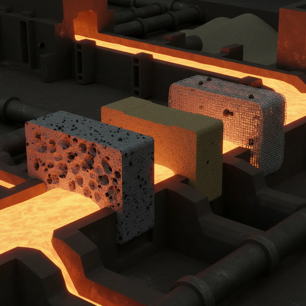
Stack ceramic foam against sand filters or fiber mesh, and it wins on every point that matters in high-volume sand casting. You get a deeper filtration range, stronger turbulence reduction, and a filter that holds up through multiple pours without breaking down.
How To Choose the Right Ceramic Filter for Your Application
The filter in your gating system does one of two things: it protects your casting, or it fails it — without any warning. Three variables decide which outcome you get: material, PPI rating, and size. Nail all three and your scrap rate drops. Miss one and you’re back to grinding out defects.
Match the Filter Material to Your Alloy
Different metals need different ceramic compositions. This isn’t a preference — it’s chemistry.
-
Aluminum alloys (~700°C pour temp): Go with Alumina (Al₂O₃) or Zirconia-Mullite. Alumina handles up to 1500°C and delivers excellent chemical resistance. It holds 35% of the filter market for good reason.
-
Cast iron (~1400°C): Silicon Carbide (SiC) is your material. It doesn’t stick to molten metal, stays acid-resistant up to 1600°C, and removes over 90% of inclusions larger than 20μm.
-
Steel (~1550–1600°C): Zirconia (ZrO₂) or Magnesium Stabilized Zirconia are your only real options here. Both are rated up to 2200°C with strong corrosion resistance. Nothing else in the ceramic filter range comes close at these temperatures.
Select PPI Based on Casting Size and Flow Rate
PPI — pores per inch — controls the balance between how well your filter captures inclusions and how fast metal moves through it.
|
Factor |
Low PPI (10–20) |
High PPI (30–50) |
|---|---|---|
|
Casting Size |
>50kg |
<10kg |
|
Flow Rate |
High (10+ L/min) |
Low (2–5 L/min) |
|
Precision |
Removes >50μm particles |
Removes >20μm, >90% efficiency |
|
Primary Risk |
Low clogging risk |
Thermal overload |
Large, high-volume pours need low PPI to prevent clogging. Precision, thin-section castings need high PPI to catch finer particles.
Size Your Filter to Avoid Overload Cracking
An undersized filter will crack. The math is simple:
Filter area (cm²) = (Pour rate L/min × 100) ÷ Max velocity (cm/s)
Keep velocity under 10–15 cm/s for aluminum and 5–10 cm/s for steel. Push those limits by just 20% and inclusion removal efficiency falls below 80%. Cracking risk goes up at the same time.
In practical terms:
– Aluminum at 700°C, 5–15 kg/min: A 50–100 cm² filter handles it. A standard 4×4 inch (16×16 cm) filter works well for a 10kg pour.
– Steel at 1600°C, 20–50 kg/min: You need 200–500 cm². Your filter cross-section should exceed the runner cross-section by at least 2×. Keep the thermal gradient below 500°C/min — go over that and you risk shock fracture.
Run through these five checks before every filter selection:
-
Match alloy temperature to material rating
-
Select PPI by casting size and flow
-
Calculate filter area with a 1.5 safety factor
-
Confirm the filter has no chemical reaction at operating temperature
-
Verify pressure drop stays under a 20% increase across its service life
Get this sequence right and the filter does its job without drawing attention — which is the whole point.
Step 1 — Measure and Cut the Filter to Fit the Gating System
Most filter failures start before the metal ever moves. They start at the measuring stage.
Get this wrong and you’ve already lost. Metal skips past the filter, or the filter shatters on first contact. You won’t see either problem until you’re holding a scrapped casting.
Measure the actual mold cavity — not the pattern. Sand compaction shifts nominal dimensions by 0.5–2 mm. That gap is enough to ruin your seal. Use calipers at the exact plane where the filter seats. Measure two axes minimum.
Then subtract 0.8 mm (1/32 inch) per side. That clearance isn’t optional. It lets the ceramic expand from heat without cracking the mold wall. Go tighter and the filter fractures. Go looser than 2 mm and molten metal slips past the filter edge, dragging inclusions straight into the cavity. In iron casting, that edge bypass alone drives scrap rates above 15%.
One more thing: sprues are tapered. Always measure at the seating plane — not the top.
For cutting, use a diamond-blade wet saw. Score-and-snap works in the field for thin filters (≤15 mm), but it’s a compromise. After every cut, run 120-grit sandpaper along the edge and drag your fingernail across it. Skip this step and loose grit goes straight into your melt.
Always start with the next stock size up, then cut down. Never piece undersized filters together.
Step 2 — Position the Filter Right in the Sand Mold
Filter placement is where most foundries leave real performance on the table — and they never know it.
You can size your filter dead-on and still wreck your casting quality with one bad positioning call. There are three locations in a sand casting gating system where a ceramic filter can sit. Each one behaves in its own way. Each one has a specific use case. Pick the wrong one and you’re fighting the physics of molten metal instead of working with it.
Know Your Three Placement Options
Sprue Cup (Top Placement)
The filter sits in the pouring cup, taking the first hit of incoming metal. It’s the easiest position to watch — you can see in real time how the filter handles impact. But that visibility comes with a cost. Direct metal impact is brutal here. Your filter needs to meet stricter performance specs to hold up. After the filter takes its hit, broken slag floats in the sprue cup. That does cut down on contamination entering the mold. This setup is common in manual green sand molding and iron mold sand-coated lines.
Base of Sprue
This is the most reliable location for vertical gating systems — as long as the sprue well is designed around it. Metal arrives with more pressure head, so filter material specs need to be higher. The upside: mold arrangement gets much easier. That’s a big deal when you’re running multiple casting sprues from a central point. One real tradeoff to watch — lower slag floating probability pairs with higher premature blockage risk. For reference, gating systems using this setup run around 6.36 kg (14 lbs) with a standard filter print.
Parting Surface Overlap (Horizontal Placement)
This position beats the other two on interception efficiency. The horizontal orientation gives you the highest interception coefficient of the three positions. You also get better slag blocking in the upper runner half, plus the easiest installation. Lighter slag floats into the slag bag on its own. So if your runner system supports it, this is the placement to go with.
Let the Data Drive the Decision
Five design configurations were tested. The results are clear:
|
Configuration |
Setup |
Air Entrapment |
|---|---|---|
|
Design 1 |
No filter |
Baseline (worst) |
|
Design 2 |
Standard filter print |
Moderate reduction |
|
Design 3 |
Standard filter print + cross-over sprue |
Low |
|
Design 4 |
Standard filter print + cross-over sprue + sprue well |
Lowest |
|
Design 5 |
Filter near top of mold |
Moderate reduction |
Design 4 wins. Design 3 comes close. Both use a cross-over sprue configuration — and that’s not a coincidence.
Here’s why: a standard gating setup sends flow direct-impinging onto the filter face. Swap to a cross-over sprue and the flow washes across the filter face sideways instead. By 0.35 seconds into the fill, a strong eddy current forms at the back of the filter print. That eddy pushes inclusions into the slag trap. They don’t drift into your mold cavity. The geometry is doing filtration work the filter alone can’t do.
Nail the Gating Ratios Before You Seat the Filter
Position means nothing if the surrounding geometry is off. Use a Sprue:Runner:Ingate ratio of 1.0:1.1:1.2. Taper your sprue at 3 degrees for clean mold stripping. A standard filter print adds about 9% to your total gating system weight — build that into your pour calculations before you run.
One more thing: seat the filter flat and flush at the seating plane. Any tilt creates an uneven flow profile across the filter face. That kills the laminar flow advantage the filter was there to deliver in the first place.
Step 3 — Secure the Filter and Assemble the Mold Without Gaps
A moving filter is a failing filter. Lock it in place. Close the mold without gaps. Those two things decide whether your filtration works or breaks down without warning.
Choose Your Securing Method by Sandbox Size
Three methods work. Pick based on your sandbox scale:
-
Tin foil wrap (sandboxes <500 kg): Wrap the filter in 0.05–0.1 mm foil, overlapping edges by 10–15 mm. Use 0.2–0.5 bar pressure. This keeps gaps under 0.5 mm on flat surfaces.
-
Sand mold groove (500–2000 kg): Carve 5–10 mm deep grooves matching the filter perimeter. Vibration-settle sand to 99% density. Gap tolerance drops to <0.3 mm.
-
Ceramic pins (>2000 kg): Space 3–5 mm pins every 50–100 mm. Set protrusion at 2–4 mm and torque each pin to 1–2 Nm. This method holds up in high-vibration environments where other options shift and fail.
Clean the Runner Before You Close Anything
Loose sand in your runner destroys filter performance before the pour even starts. Particles as small as 0.05 mm cause clogs in 80% of cases. That blocks 30–70% of flow in filters with 0.5–2 mm pores.
The sequence:
1. Blast compressed air at 0.3–0.5 bar for 30–60 seconds
2. Vacuum extract residuals at ≥0.5 m³/min
3. Re-inspect — if porosity exceeds 5%, repeat
Target: less than 0.01 g of loose sand remaining.
Close and Verify
Use 0.5–1.0 bar/cm² clamp force. Hold for 2–5 minutes. Check every edge with a feeler gauge. Maximum allowable gap: 0.2 mm.
Then check the filter seal on these three points:
– No light penetration under 100 lux illumination
– Zero fluorescent dye bleed after 1 minute
– Pressure decay under 5% in 30 seconds at 0.1 bar hold
Poor edge contact causes 10–25% metal bypass. That bypass creates defects in 15% of finished castings. Gap-free assembly cuts those rejections out. Foundries that nail this step reduce overall rejects by 40%.
Step 4 — Prime the Filter Before Pouring Metal
Air trapped in your filter pores is a silent defect waiting to happen. Before a single drop of metal moves, those pores must be clear — and priming gets that done.
The process is mechanical and straightforward:
-
Cover the upstream side — Fill the filter box until molten metal covers the filter’s inlet face
-
Seal the outlet — Close the exit well with a sealable cover before applying any vacuum
-
Pull vacuum in steps — Use a fan or air venturi to draw air out of the exit well, ramping up at 0.1 to 10 kPa per second
-
Watch for breakthrough — Keep pulling until metal starts flowing through the filter face
-
Release fast — Drop the vacuum at once and open the outlet
The full sequence runs between 1 and 120 seconds. Most operations land in the 2–30 second window — that’s your target range.
A conductive probe sits at the bottom of the well. It detects metal breakthrough and triggers a solenoid valve to release the vacuum the moment flow is confirmed. No guessing required.
Fan-based systems keep this process clean. You skip the vacuum tank, get faster air removal, and hold a smooth vacuum ramp even with imperfect seals. After priming, metal keeps flowing under low inlet head. The filter stays open with no backpressure to fight.
Minimum filtration area: 645 cm². Filter thickness should run 2.5 to 7.6 cm for solid priming performance.
Step 5 — Pour the Molten Metal at the Correct Temperature and Speed
Temperature and speed aren’t variables you adjust by feel. These two factors decide whether your ceramic filter delivers clean metal — or does nothing while turbulence wrecks your casting.
Get Your Temperature Window Right
For aluminum alloys — A356, A380, A360 — your optimal pouring range is 680–750°C. That range isn’t arbitrary:
-
680–700°C gives you the best surface finish
-
700–750°C peaks mechanical properties (hardness, tensile strength)
-
Below 680°C — fluidity drops fast. Cold shuts form before corners fill
-
Above 750°C — gas entrapment, blowholes, and rough surfaces follow
Stay under 730°C and your internals come out defect-free. Push past it and you’re gambling with every pour.
For steel, stay at 1370–1500°C or above. That keeps the metal flowing through the full fill cycle. Drop below it and the metal stiffens mid-pour.
Control Your Pour Speed Like It Matters — Because It Does
For aluminum, target velocity sits between 2.2 and 2.8 cm/s. That narrow band gives you maximum hardness (65.4 Rockwell) and tensile strength (127 N/mm²).
Go slower than 2.0 cm/s and thin sections solidify before they fill. Go faster than 2.8 cm/s and turbulence takes over. Inclusions, dross, and gas holes follow fast. At 16 cm/s, tensile strength collapses to 68.5 N/mm² — that’s close to half.
Calculate your target speed before you pour:
V = H ÷ T (V = velocity in cm/s, H = ladle height in cm, T = pour time in seconds)
Two more things that kill good pours:
– Keep metal level above the filter’s upstream face throughout the entire pour — drop below it and air pulls through
– Thin-walled sections need faster speed than thick sections — slow down on a thin wall and you’re chasing cold shuts
How To Inspect and Remove the Filter After Casting
The filter pulled out of a cooled mold tells you more about your pour than any log sheet ever will.
Let the casting reach room temperature first. Removing it too soon creates thermal stress. That stress damages surfaces — and a surface crack can’t be fixed after the fact.
Removal sequence matters. Work bottom-up. Pull the filter upward from the lower mold sections. This protects the casting surface all the way through.
Once the filter is out, inspect it right away:
-
Count the inclusions — high slag volume means your melt wasn’t clean before it hit the gating system
-
Check for sand and dross — uneven debris across the filter face points to inconsistent flow rates
-
No cleaning required — ceramic foam filters capture 100% of surface debris on contact. What you see is what entered your mold. Nothing more, nothing less.
Compare your casting against these benchmarks:
|
Inspection Point |
Filter Working |
Poor Filtration |
|---|---|---|
|
Slag inclusions |
6–12% scrap reduction; up to 20% yield gain |
High inclusion rate, voids |
|
Porosity |
Even distribution, no surface pores |
Misruns, cold shuts |
|
Surface defects |
No cracks or slag pitting |
Flux leakage, discontinuities |
Follow up with NDT. Magnetic particle testing catches shallow cracks down to 0.003 inches — defects your eye won’t pick up on its own. Liquid penetrant finds surface openings after dye dwell time. Visual inspection then closes the loop on gas holes and slag inclusions.
The filter doesn’t lie. What it captured shows you where your process broke down.
Best Practices To Maximize Ceramic Filter Performance in Sand Casting
Getting the filter right is just the starting point. How you store it, handle it, install it, and manage the process around it — all of that determines whether you get the full performance gains or leave most of them on the floor.
Moisture is your first enemy. Filters stored in damp conditions absorb water. Molten metal hitting a wet filter causes steam to expand fast. The pressure builds in an instant. The filter explodes before filtration can even start. Store foam filters in dry conditions, sealed until use. No exceptions.
Inspect before you install. A hairline crack can be invisible to the naked eye. Under metal pressure, that crack causes immediate filter failure. Hold each filter up to direct light before seating it. See any fracture? Discard it.
Blow out the print with compressed air before setting the filter. Loose sand sitting beneath a seated filter goes straight into your casting. One German foundry tracked this closely — filters with edge gaps under 0.5 mm showed 15% better dirt removal compared to loose-fit setups. The prep work and the result are inseparable.
Keep a filter log. Track PPI grade, supplier, pour weight, scrap rate, and inclusion data across batches. Foundries that treat ceramic filtration as a process parameter — not a throwaway consumable — are the ones cutting scrap rates by 15–40% across production runs.
One more rule that most operations skip: ceramic foam filters are single-use. Pores block on first use. Thermal cycling weakens the structure. Reuse leads to failure. The defects that follow are expensive to diagnose and hard to predict before damage is done.
Conclusion
Getting ceramic filters right in sand casting isn’t complicated — but the details matter. A lot.
Match the casting filter to your alloy and flow rate. Position it with care, secure it tight, and pour at the right temperature. Do those things every time. You’ll see the results: fewer inclusions, cleaner internal surfaces, and castings that pass inspection on the first try.
That’s the real payoff here. Not just better parts — less rework, less scrap, less money lost on the foundry floor.
Just getting started? Pick one casting run. Apply everything covered in this guide. Treat it as a controlled test. Compare your defect rate before and after using ceramic filters in sand casting. Let the numbers tell the story.
The foundries producing the cleanest castings aren’t doing anything magical. They execute the basics better than everyone else. That’s it.
Now go do the same.