Slag inclusions, cold shuts, porosity — most casting defects don’t show up until you’ve already wasted a pour. The fix is often simpler than a full process overhaul: one well-placed mesh filter in your gating system.
But “just drop a filter in” is where many foundry workers stop. That’s where the problems start.
Using mesh filters in sand casting the right way takes more than placement. You need the correct filter type, the right position, and the proper pour technique. Get those three things right, and you get a clean, inclusion-free casting. Miss them, and the part gets scrapped.
This guide covers every step — from mold prep to post-pour inspection. Each section includes the hands-on detail that makes a real difference on the shop floor.
What Are Mesh Filters in Sand Casting (And Why They Matter)
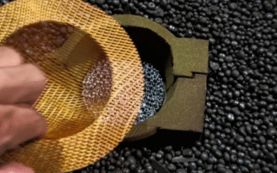
A mesh filter is a woven net that sits inside your gating system. It catches everything the molten metal tries to carry into the mold.
These filters are made from fiberglass or high-silica materials, woven into a tight grid structure. They handle temperatures up to 900℃. That covers aluminum, iron, steel, and copper pours — no breakdown, no melt contamination.
Here’s what they intercept:
-
Slag and oxide inclusions that form during melting or ladling
-
Sand particles dislodged during the pour
-
Gas bubbles trapped in the metal stream
-
Non-metallic debris that would otherwise become internal defects
The filtration does two jobs at once. First, it screens out particles. Second, it slows and smooths the metal flow. Turbulent, air-trapping flow becomes laminar flow — the kind that fills the mold cavity in a clean, controlled way.
The results show up in your finished castings. You get better hardness uniformity, stronger bending strength, and a smoother surface finish. Machining time drops. Scrap rates fall. Both of those hit your bottom line.
Filter material plays a big role here. Alkali-free fiberglass outperforms metallic wire mesh for aluminum work. You avoid iron contamination risk, get better impurity absorption, and see stable performance from start to finish of the pour.
Types of Mesh Filters: Choosing the Right One Before You Start
Not all mesh filters do the same job. Pick the wrong one and you don’t just lose filtration efficiency — you risk ruining the entire pour.
There are three filter types you’ll run into in sand casting work. Each has its own structure, temperature limit, and metal compatibility. Here’s how they break down:
The Three Main Types
High-Temperature Fiberglass Mesh
Inorganic fibers woven into an open grid. Open area runs 50–70%, so flow resistance stays low. Temperature range: 1,200–1,400°C. The downside is physical fragility — these filters crack under pressure and don’t hold up to rough handling. Use them as a secondary filter layer in iron pours. Don’t rely on them as a standalone solution.
Ceramic Foam Filters
This is the go-to filter for high-temperature metal casting. The pore structure is uniform, rated from 10 to 50 ppi. Filtration efficiency exceeds 95% for inclusions. It handles temperatures above 1,600°C and holds up against thermal shock. Brittle by nature, but seat it right and it outperforms everything else in its class. For steel pours at 1,450–1,550°C, this is your default pick.
Woven Wire Mesh
Available in plain, twill, or Dutch weave patterns. Each pattern changes the open area and how precisely it filters. Stainless SS304/316 tops out at 800°C; nickel alloy grades reach 1,000°C. Of the three types, woven wire has the highest mechanical strength. For aluminum work (660–750°C), SS316 mesh in the 30–60 mesh range handles corrosion well.
Matching Filter to Metal
|
Metal |
Pour Temp |
Best Filter |
Avoid |
|---|---|---|---|
|
Aluminum alloy |
660–750°C |
Ceramic foam or SS316 wire mesh |
Fiberglass (melt risk) |
|
Cast iron |
1,150–1,300°C |
Fiberglass or ceramic foam |
Wire mesh (except nickel alloy) |
|
Steel |
1,450–1,550°C |
Ceramic foam (primary) |
Wire mesh (all grades) |
Mesh Size: Precision vs. Flow Rate
Mesh size controls two things at once: how fine the filtration is, and how much you’re slowing down metal flow. These two factors push against each other, so you need to find the right balance.
A 20 mesh filter opens at 841μm — coarse filtration, high flow rate, solid for catching large sand clumps. A 200 mesh filter narrows to 74μm — near pharmaceutical-grade precision, but resistance builds fast. For most sand casting applications, stay between 30 and 100 mesh. That range catches meaningful inclusions without choking the sprue.
Here’s a simple decision framework:
-
Identify the smallest particle you need to catch — then pick a mesh that captures particles 2–3× that size
-
Flow rate is the constraint? Go coarser first. Add more filter surface area instead of loosening the mesh size after setup
-
Above 1,000°C, wire mesh is off the table — use ceramic foam or fiberglass
-
For corrosive or reactive metals, go with SS316 or titanium mesh. Skip anything that reacts with the alloy chemistry
-
Open area above 50% keeps clogging risk low — Dutch weave patterns like 50×250 mesh can hit 59% open area. That’s worth factoring in for longer pours or high-slag-content melts
Get the filter type right before you think about placement. A ceramic foam filter in the wrong position still beats a wire mesh filter that was never built for your pour temperature.
Step 1 — Prepare Your Sand Mold and Gating System
The filter can’t do its job if the system behind it is built wrong. A mesh filter dropped into a bad gating system is just an obstacle — not a solution.
Your gating system has four parts that need to work together: the pouring basin, sprue, runner, and gate. Each one controls what the metal does before it reaches your filter.
Here’s the setup that works:
-
Pouring basin — Acts as the funnel inlet. It regulates flow and starts separating slag before metal hits the sprue. Target height: 20 mm
-
Sprue — The vertical channel. Standard height is 105 mm, with a base well depth of 13.10 mm. The well absorbs momentum and stops turbulence from pushing through
-
Runner — Horizontal channel that moves metal toward the cavity. Keep transitions rounded. Sharp corners create turbulence and erode sand
-
Gate — The cavity entry point. No sharp edges. Ever. Sharp edges crack sand, and cracked sand becomes inclusions
Get the Gating Ratio Right
Use a 1:2:1 ratio — sprue to runner to gate. This keeps flow velocity steady across the system. It also holds the Reynolds number above 2,000, which is your target for stable laminar flow.
Place your filter at the choke point — the narrowest cross-section at the sprue base. That’s where it controls velocity best. Size the filter to match your gate area. A gate area of 524.7 mm² needs a filter sized to that cross-section. Undersized filters cause bypass. Bypass defeats the whole purpose.
Sand Type Changes Everything
Your sand choice has a direct impact on how well the filter seats and seals:
|
Sand Type |
Filter Impact |
|---|---|
|
Green sand |
Coarser surface increases bypass risk and sand erosion around filter edges |
|
Resin bonded |
Smoother, harder surface gives a better filter seal — simulations show lower porosity in gray cast iron pours |
|
No-binder |
High mold strength, precise filter placement, minimal turbulence |
Resin-bonded sand is the stronger choice for filtration precision. The smoother mold surface cuts down on hotspots and holds the filter in position.
The Prep Sequence
-
Place your pattern in the sand and imprint the cavity shape
-
Install the pouring cup, sprue, runner, and gate — add the filter at the choke point
-
Remove the pattern after the gating is set
-
Verify before you pour: pouring time should hit around 3.27 seconds, no sharp edges anywhere in the system, and Re stays above 2,000
Get this foundation right and the filter performs as it should.
Step 2 — Select the Correct Filter Size and Mesh Rating
Filter sizing is math before it’s intuition. Get the numbers wrong and no amount of careful placement saves your pour.
Two variables control everything: effective filter area and mesh rating. They work together. One sets your flow capacity. The other sets your filtration precision.
Calculate Effective Area First
Use this formula before you touch a filter:
Airflow velocity (fpm) = flow rate ÷ filter surface area
A real example: 200 CFM through a 0.50 sq ft filter produces 400 fpm velocity. That number tells you whether the filter can handle your pour rate without choking the sprue. Too high a velocity? Increase the filter surface area — don’t loosen the mesh.
Mesh Rating: Where Precision Meets Flow
Here’s the tension every foundry worker faces: finer mesh catches smaller particles, but it builds resistance fast. For most sand casting work, the target is the medium efficiency range — capturing particles in the 1–5μm band at 60–95% efficiency. That’s your sweet spot.
Two errors kill more pours than anything else:
-
Over-fine mesh — restricts flow, causes pressure drop, starves the mold cavity
-
Over-coarse mesh — lets small sand particles and slag straight through, making the filter useless
Step 3 — Position and Secure the Filter in the Gating System
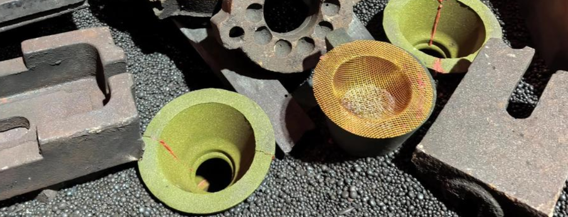
Filter placement is what most foundry workers get wrong. You can pick the right mesh rating, prep a clean mold, and still ruin the pour by putting the filter in the wrong spot.
Where the Filter Goes Matters More Than You Think
Two positions are common. Each gives a different result.
Filter near the casting (lower gating system) — This is the stronger choice. It holds back the metal stream across the full runner length. Flow stays subcritical all the way into the mold cavity. You get slower, controlled filling. Less erosion. Fewer inclusions.
Filter under the pouring basin — This only holds back the initial stream. Metal picks up speed again before it reaches the cavity. That defeats much of the filtration. Use this position only when the geometry leaves you no choice.
For horizontal runner placement, set the filter crosswise in the runner. This cuts down the distance metal travels after passing the filter. The closer the filter sits to the casting, the longer subcritical flow holds. At the ingate entrance, direct metal contact primes the filter faster. Post-filter velocities drop sharply, with filling stabilizing between 0.3 and 0.6 seconds.
Locking the Filter in Place
An unsealed filter is the same as no filter. Three fixing methods work:
-
Refractory cement — Apply it to the filter edges. This closes any bypass gaps. It’s a must for hollow ware systems where pressure builds unevenly
-
Chaplet support — Mechanical backing that stops the filter from shifting during the pour
-
Filter seat or slot — The HOLLOTEX C5-FH two-piece insulating holder seats ceramic foam filters with a tight, exact fit. It supports both horizontal and vertical placement
Verify Before You Pour
Check two things after securing the filter:
-
No bypass gaps — Any opening around the filter edge lets unfiltered metal into the cavity
-
Flow simulation confirms subcritical velocity post-filter — Running MagmaSoft or something similar? A small bubble below the filter at 0.5 seconds is a minor flag. It should clear by 0.6 seconds. If it doesn’t, recheck your seal
Industrial tests back this up. Filtered systems with proper near-casting placement show lower oxide and inclusion counts compared to filters placed high in the gating system. The gap in results is real and repeatable.
Step 4 — Preheat the Filter and Assemble the Mold
A cold filter dropped into a hot pour is a liability. The temperature gap causes thermal shock. It cracks the ceramic structure and can trigger dangerous steam bursts from trapped moisture. Preheating is not optional prep — it’s what keeps the filter alive through the pour.
Target temperature by filter type:
-
Ceramic foam (aluminum alloys): Minimum 260°C. For high-performance pours, push to 600–650°C. That range opens the ceramic structure, drives off surface moisture, and prepares the filter for metal contact before it arrives
-
SiC filters (iron casting): Preheat large-format filters. Their low thermal expansion coefficient handles most pours fine, but skipping preheat on bigger units cuts service life short
-
Zirconia filters (steel): Rated to 1,700°C, but preheat still applies
Heat time: 15–30 minutes, electric or gas. No shortcuts.
At assembly, check three things:
-
Filter top face sits flush or below the parting line — never proud
-
Minimum 5–10 mm overlap on all four seating edges to prevent collapse under metal weight
-
Zero bypass gaps around the filter perimeter
Close the mold, then run a priming pour 15–30 seconds before the main pour. Use 2–3% of total cast weight for filters under 12 inches. On a 50 kg part with a 10-inch filter, that’s 1–1.5 kg of priming metal. Below 500°C, the filter stays water-resistant and aluminum won’t push through the fine pores. The prime pour confirms the filter is ready to go.
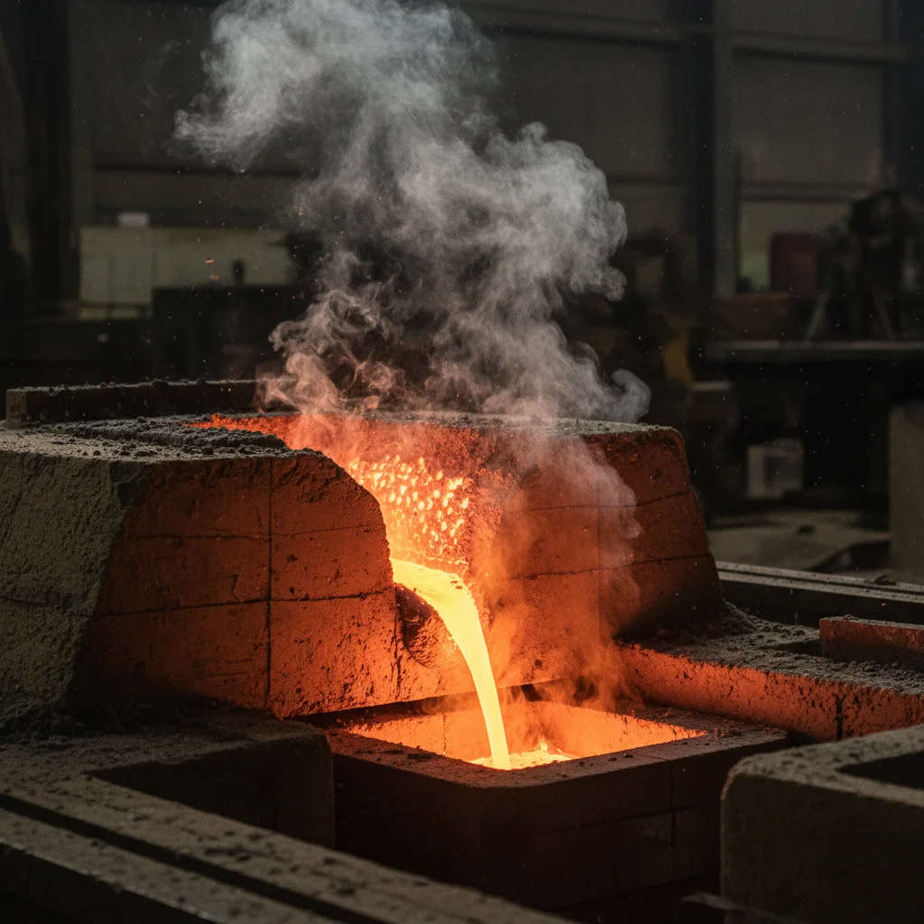
Step 5 — Pour the Molten Metal Through the Filter
The filter is seated, the mold is closed, the priming pour is done. Now comes the pour itself — and this is where technique separates clean castings from scrap.
Control your flow rate from the first second. Fill the CFF filter box at a steady, measured rate. A large vortex forming in the filter box is a failure signal. Vortex flow generates inclusions. It also destroys the filter’s ability to capture the inclusions already in the melt. Keep the stream controlled and consistent.
The Pouring Sequence That Prevents Clogging
Follow this order:
-
Pour molten metal into the filter plate first — let it prime before anything else moves
-
Fill the flow trough ahead of the launder baffle — metal builds on both sides of the filter
-
Open the baffle — this exposes the filter to full pressure head, drives 100% perfusion, and sends rapid hot metal into the casting
One rule through all three steps: no beating, no shaking, no interference. Any disturbance to natural infusion causes local perfusion — patches of the filter that never prime. Those patches let inclusions pass straight through. The filtration you built the whole system around stops working.
Read the Flow While You Pour
|
Normal State |
Warning Sign |
|---|---|
|
Steady metal level in launder |
Excessive fluctuation — slag content rising |
|
Smooth, rapid flow after baffle opens |
Large vortex — perfusion dropping |
|
Full filter immersion, natural infusion |
Local perfusion — filter not engaged |
Keep both sides of the filter plate immersed throughout. The launder level starts swinging? Slow the pour and stabilize before you continue.
Step 6 — Cooling, Demolding, and Post-Pour Inspection
The pour is done. Now patience becomes the skill.
Cooling time isn’t guesswork — it’s math. Use the solidification formula: t_s = C × (V/A)². For a 1-inch aluminum wall, that’s 4–16 minutes. For steel, 100–225 minutes. Don’t skip ahead. Sand molds have low thermal conductivity (0.2–1.0 W/m·K). That extends cooling 20–50% longer than metal molds. The slower pace protects you from hot tears and distortion.
Minimum shakeout time = 1.5 × solidification time. Gray iron at a 2-inch section solidifies in 45 minutes. Don’t demold before 67 minutes. Pulling aluminum before 30 minutes on a ½-inch wall causes distortion. Early demolding causes 15–30% rat-tail cracks in sand-cast steel. That’s a serious risk — don’t take it.
Demolding Procedure
-
Confirm mold surface temperature is below 150°C
-
Vibrate or rap the pattern 3–5 times before lifting
-
Lift to 50% height, inspect for sticking — re-vibrate if needed
-
Complete demolding at less than 20% solid fraction remaining
Post-Pour Inspection
Check every casting against these limits:
|
Defect |
Detection Method |
Acceptance Limit |
|---|---|---|
|
Misrun |
Visual, X-ray |
<5% surface area |
|
Shrinkage |
Dye penetrant, CT scan |
<2% volume void |
|
Cracks |
Ultrasonic, magnaflux |
<10 mm length, <1 mm depth |
|
Inclusions |
Section polish + microscopy |
<0.5% area fraction |
After removing risers and gating, weigh the filter pre- and post-pour. Ceramic foam filters should hit >95% capture efficiency. Cut a 20–50 mm transverse slice downstream of the filter, polish it, and run SEM/EDS. Target: fewer than 10 oxide particles/cm² above 50 μm. An Al-Si7Mg casting with a 30ppi foam filter shows 85–98% non-metallic removal under normal conditions. Anything above 20 inclusions/mm² means your filter has failed.
Controlled cooling gets you to 92% first-pass acceptance. Rush the demold and defect rates jump 25%. That includes an 18% porosity increase in aluminum castings alone.
Filter Disposal After the Pour
|
Filter Type |
Reuse? |
Disposal |
|---|---|---|
|
Ceramic foam |
Single-use |
Crush to <50 mm, landfill or recycle silica |
|
Stainless mesh |
Up to 50 cycles if <10% clogged |
Ultrasonic clean at 40kHz, then dry below 120°C |
|
Zirconia |
Never reuse |
Crush; treat as hazardous waste |
The filter that just cleaned your casting tells a story. Read it before you throw it away.
Best Practices for Maximizing Filter Performance Across Different Metal Types
Each metal behaves in its own way under filtration pressure. What works for aluminum will fail on steel. What holds up in a copper pour breaks the logic for that metal entirely.
Here’s the metal-by-metal breakdown that makes a real difference:
Aluminum Alloys (660–750°C)
Flow velocity is your biggest variable. Keep it at or near 0.2 m/s through the filter. At that speed, filtration efficiency peaks. Push faster and efficiency drops across every particle size class. A ceramic foam or SS316 wire mesh in the 30–60 mesh range handles both the temperature and the corrosion load well. Don’t let velocity creep up just to chase pour speed. That tradeoff costs you more than it gives.
Cast Iron (1,150–1,300°C)
Ceramic foam filters are your foundation here. High slag content makes clogging a real risk — so scale your filter count to match melt volume. One filter per 500–800 kg for 20 PPI keeps pressure drop at a manageable level. Go to 25–30 PPI and tighten that ratio to one filter per 300–500 kg. Stick to those numbers and pressure stays under control.
Steel (1,450–1,550°C)
Nothing holds up in this heat range except ceramic foam. Zirconia-grade filters rated to 1,700°C give you the safety margin you need. Preheat your filters before use. Cold filters crack on contact — no exceptions.
One rule covers all three metals: match your filter to the metal, not to what’s most convenient.
Conclusion

Mesh filters aren’t optional extras — they’re the difference between a casting you’re proud of and one you grind down, patch up, or scrap.
Three things matter most: choose the right filter type for your metal, seat it in the gating system, and pour with consistent control. Get those three things right. You cut out most inclusions, turbulence defects, and post-pour headaches before they start.
Learning how to use mesh filters in sand casting isn’t a one-time fix — it’s a habit that builds over time. Every clean pour sharpens your instincts for the next one.
So here’s your next step: go back to your current gating setup. Check where your filter sits. Look at what rating you’re running. See if it matches your metal type. Odds are one small adjustment is waiting to make a real difference.
Small changes. Cleaner metal. Better castings. Start there.