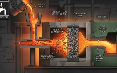
Ceramic filters handle multiple types of contamination at once. These contaminants fall into clear categories. Each one impacts your casting in different ways.
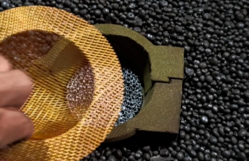
Non-metallic inclusions rank first on the removal list. Oxide films form during melting and pouring. Slag bits break free from furnace linings. Sand particles migrate from molds. Ceramic foam filters catch these threats through depth-mode filtration. The ceramic’s porous structure traps particles. Molten iron flows through connected cells. Contaminants get stuck along the way.
Heavy metal removal hits strong benchmarks. Lead and chromium both achieve 99.9% removal efficiency. These contaminants damage casting integrity at tiny scales. Standard ceramic filters remove them before they stick in your final product.
Inclusion filtration efficiency ranges from 30-90%. This depends on how clean the metal is when it enters the system. Dirty iron sits at the lower range. Cleaner melts reach maximum efficiency. The filter’s PPI rating plays a big role here. Iron alloys work best with 10ppi/100csi to 30ppi/300csi specifications. Lower PPI handles larger inclusions. Higher PPI catches smaller particles. But it can restrict flow.
Gray iron and ductile iron need different setups. Gray iron requires minimum 3:1 filter-to-gate ratio. Ductile iron demands 5:1 or higher. Ductile iron has a nodular graphite structure. This makes it more sensitive to inclusion damage. You need more filtration capacity. This protects nodule formation. It also keeps mechanical properties intact.
Primary Contaminants Removed by Ceramic Filters
Ceramic filters in iron casting tackle four main enemy groups. Each contaminant type threatens your casting in different ways. Know what gets caught. This helps you pick the right filtration strategy.
Non-Metallic Inclusions: The Silent Quality Killers
Oxide films top the removal priority list. They form when molten iron meets oxygen during transfer and pouring. Aluminum oxide, silicon oxide, and iron oxide create thin layers. They float through your melt. Ceramic filters trap them through depth filtration. The connected pore structure catches these films before they reach your mold cavity.
Slag particles break loose from furnace linings and ladles. They carry sulfur compounds and silicates. These chunks range from tiny to visible sizes. The ceramic matrix blocks them at multiple depth levels. Larger pieces stick to outer surfaces. Smaller bits get caught deeper in the filter body.
Sand grains move from mold walls during pouring turbulence. Silica sand creates hard spots in finished castings. These spots ruin machining tools. They also create weak points under stress. Ceramic filters with 10ppi to 30ppi ratings handle sand removal well. The pore size matches common sand grain dimensions.
Metallic Contaminants: Precision Removal Performance
Heavy metal removal shows strong numbers. Lead achieves 96.8-98.1% removal efficiency across standard ceramic filter applications. Historical casting studies pushed this to 98.6% in controlled conditions. Your filtered iron stays cleaner than regulatory requirements.
Chromium removal hits 99.9% efficiency with the right sized filters. This matters for ductile iron grades. Even trace chromium affects nodule formation. Mercury drops by 88.9-92.5% during filtration. Effluent concentrations fall to 0.004 mg/L. This beats WHO standards by 33%.
Inclusion removal efficiency spans 30-90% range based on incoming metal cleanliness. Dirty charges with heavy slag content sit at 30-40% efficiency. Pre-cleaned melts reach 85-90% capture rates. The filter acts as your final defense layer. It catches what furnace deslagging missed.
Pore structure drives these results. Smaller pore diameter increases capture rates. But it also slows flow. You need to balance filtration needs against production speed. Your casting cycle time depends on this tradeoff.
Sand and Mold Material Particles
Molding sand erodes constantly during iron pouring. Sand grains break free from sprues, runners, and gating systems. Turbulent metal flows through channels and pushes these particles loose. The particles match your molding sand specs: 0.1-0.8 mm diameter range with mean sizes between 0.2-0.45 mm. The composition mirrors what you put in the mold. Silica content runs 94-98% SiO₂ for cast iron applications. Clay and binder residues make up the rest.
AFS fineness numbers tell you what particle sizes dominate your sand system. Higher numbers mean smaller average grain diameter. The calculation uses ASTM sieve analysis. It applies weighting factors per grain size fraction. Most foundries target AFS 110-80 specifications for iron work. This gives you average grain diameter of 0.14-0.20 mm in recommended Disa systems.
Grain shape affects how sand behaves during erosion. Rounded grains need less binder. They flow through gating systems with less resistance. They have lower surface-area-to-volume ratios. Angular and sub-angular grains resist movement better. They pack tighter in molds. But they break loose faster at high metal flow velocities.
Ceramic filters catch these eroded particles before they embed in castings. Grains larger than 0.45 mm create rough surface finishes. You get sand inclusions or “Sandwiched between sand layers” defects. Embedded particles cut tensile strength at stress points. Fine grains below 0.2 mm cause different problems. They block gas escape routes with 6-10% clay content in green sand systems. Trapped gases form porosity and pinholes.
The facing sand layer adds 20-30 mm of vulnerability. This layer uses finer grain distributions than backing sand. It contains 25% fresh sand mixed with 5% sea coal and high proportions of fine molding sand. These fine particles erode first during pour turbulence. Ceramic filters with 10-30 ppi ratings match this particle size range.
Impurity composition matters beyond pure silica. Iron oxide, alumina, limestone, magnesia, soda, and potash change fusion temperatures. Too much iron oxide or alkali metals lower melting points. This causes burn-in defects. Sand fuses to casting surfaces. High-melt steel applications demand minimum 98% SiO₂ purity to prevent these reactions. Cast iron tolerates 94-98% ranges. Lower pouring temperatures make this possible.
Binder content sits at 6-11% in modern sand systems. Organic and inorganic binders leave ash residues. Molten iron breaks them down. Ceramic filters trap binder breakdown products along with sand grains. This dual removal protects your casting from multiple contamination sources.
Oxide Films and Dross
Molten iron reacts with oxygen the moment it leaves the furnace. This reaction builds thin oxide layers across the metal surface. These films are made of iron oxide, silicon oxide, and aluminum oxide. The layers get thicker during transfer from furnace to ladle. They grow more during pouring into molds. Ceramic filters in iron casting stop these oxide films before they ruin your final product.
Dross forms in a different way than simple oxide films. It mixes oxide layers with trapped metal droplets and slag bits. This creates a semi-solid mass. The mass floats on the molten metal surface. Dross breaks apart during rough pouring. Chunks flow into your gating system. Ceramic foam filters catch these dross bits using depth filtration. The connected pore structure traps pieces at many levels.
Furnace atmosphere control cuts oxide film growth rates. Controlled burner settings make oxide films with less oxygen spread. This slows down how fast they get thicker. Temperature control matters just as much. Lower superheat temperatures limit oxide formation. But you need enough flow for complete mold filling. The balance sits between 1450-1550°C for most iron grades.
Dross makeup varies by production method. Metallic iron content runs 30-40% in typical foundry dross. The rest is oxide compounds and trapped slag. Dross losses typically hit 4% of total melt weight. Research shows you can cut this to 2% with proper skimming and filtration. This reduction saves over 58 trillion Btu of energy across the whole industry.
Ceramic filters stop oxide films two ways: by straining them out and by sticking to them. Film bits stick to ceramic surfaces. The twisting path through connected pores creates more contact points. Each contact gives films a chance to attach. Filters with 10-30 ppi ratings balance how well they catch things against flow resistance. Higher PPI ratings catch smaller oxide pieces. But they slow metal flow and create more back pressure.
Oxygen spread rates control how fast oxide films thicken. Controlled atmospheres with lower oxygen levels reduce this spread. This keeps films thinner and more brittle. Brittle films break into smaller pieces. Smaller pieces get caught more by ceramic pores. The filter removes what atmosphere control couldn’t stop.
Slag and Metallurgical By-products
Slag has a unique chemical makeup. This sets it apart from other waste materials. You’ll find silicates and oxides dissolved inside. Main compounds? Dicalcium silicate (2CaO·SiO₂) and magnesium oxides (MgO). Some base metals stay mixed in too. The density differs from pure molten iron. Ceramic filters use this difference to separate slag. They work through physical straining and buoyancy.
Copper slag leads the non-ferrous metallic slag market. Aluminum dross and lead-zinc slag come next. Smelting and refining copper, aluminum, lead, zinc, and nickel create these materials. The steelmaking slag market hit USD 7,800 million in 2025. Expected growth? 26.01 billion by 2033 at a 5.5% CAGR. Iron and steel slag processing reached USD 23,707.4 million in 2025. These figures show the massive slag flow through foundry systems.
Slag properties shape how filtration works. The material absorbs moderate amounts of water and has a rough surface. This roughness makes slag stick to ceramic pore walls. Ceramic filters trap slag particles before they reach mold cavities. Captured slag goes through briquetting, granulation, or pelletization. Foundries sell this processed material for cement, concrete mix, and road building. Farms buy it for soil treatment and fertilizer. Waste becomes profit.
Microscopic Impurities in Different Iron Types
Your cast iron grade determines what tiny contaminants lurk in the melt. Gray iron can handle contamination levels that ruin ductile iron quality. Each type needs its own filtration specs.
Gray Iron: The Forgiving Workhorse
Gray iron puts up with tougher conditions than ductile iron. Surface iron contamination stays safe up to 5000 ppmw. The flake graphite structure hides small impurity clusters. But you still need filtration.
Aluminum oxide (Al₂O₃) and silicon dioxide (SiO₂) are the main microscopic inclusions. Phosphorus traces add small problems. These particles measure in microns. Iron oxides below 10 μm slip past rough filters. They get stuck in castings without showing surface defects.
Use at least 10 ppi ceramic filters to catch these threats before damage happens. The 100 csi cell density gives enough surface area. Particles stick to pore walls as metal flows. Gray iron work handles this filtration level without blocking flow.
Ductile Iron: Zero Tolerance for Contamination
Ductile iron production needs extreme cleanliness. Atomic iron contamination above 1500 ppmw destroys your yields. Gray iron tolerates 5000 ppmw. The nodular graphite structure fails under impurity stress. Nodules need clean conditions to form.
Ceramic filters for ductile iron need 5:1 minimum ratios. Filter pore size versus inclusion size sets this spec. Particles under 10 μm from corrosion and metal dusting need strong capture. These tiny threats pass through regular filters. They ruin magnesium treatment. Temperature drops 20-25% once atomic iron crosses the limit. Platinum catalyst clumps follow contamination spikes.
Specialized Iron Grades: Tighter Control Windows
Malleable iron falls between gray and ductile for cleanliness. The high carbon matrix above 2.14 wt% C brings unique filtration challenges. Target particles below 5 μm diameter. Bigger oxide and slag pieces warp temper carbon formation. Keep total non-metallic content under 2000 ppm.
Compacted Graphite Iron (CGI) needs the finest filtration in regular foundry work. 8-12 ppi specifications beat the 10 ppi gray iron standard. Vermicular graphite stability fails above 1000 ppm non-metallics. Filter pore sizes between 5-8 μm fit this contamination limit. CGI’s structure sits between flake and nodular forms. This in-between position leaves no room for inclusion defects or sulfide contamination.
Blue Dust ore grades deliver high iron with few impurities. Hard Laminated grades carry more SiO₂ and phosphorus. Adjust your filtration based on incoming material quality. Cleaner charges need less aggressive pore sizes. Dirty melts need maximum capture power.
Filtration Mechanisms and Efficiency
Three core mechanisms drive ceramic filter performance in iron casting systems. Physical entrapment does most of the work. Adsorption helps too. Chemical bonding between filter materials and contaminants adds extra protection. Know these mechanisms to pick filters that match your contamination profile.
Physical Entrapment: The Primary Capture Method
Pore size versus particle size sets capture rates. Ceramic filters trap particles bigger than their pore openings through direct blocking. Smaller particles travel winding paths through connected cells. They hit pore walls many times. Surface roughness creates contact points. Particles stick at these zones.
Polycarbonate filters with 1-μm pores show this. They catch 49% of 47 nm particles in lab tests. Efficiency jumps to 68% for MS2 virions at about 25 nm diameter. The smaller viral particles travel more random paths. This boosts wall contact. Filters with 3-μm pores drop to 22% efficiency at 63 nm particle size. Bigger openings let more particles escape. But efficiency climbs to 69% average at 0.35 μm particle diameter. The particles near pore size. Direct blocking replaces random collision.
PTFE ceramic materials deliver better capture across size ranges. Filters with 0.3-μm and 3-μm pores hit at least 98.4% efficiency for particles between 10-600 nm. Tests using NaCl and polystyrene latex particles prove this. Efficiency tops 99% for 0.35-μm particles under loaded conditions. The filter keeps working even as trapped material builds up inside the pore structure.
Real-World Efficiency Parameters
Iron foundry conditions differ from lab settings. Flow rates, metal temperature, and contamination loads shift all the time. Best filtration efficiency runs between 91.84-95.71% at balanced operating conditions. This data comes from pontoon mesh rotary filter studies handling cloudy water with suspended particles. The test parameters match foundry gating system flows: 400 m³/h throughput, 2.5 g/L suspended solids, 25 L/min backflush rate, and 8-hour run cycles.
Particle load affects capture rates a lot. Efficiency increases 14.60% as sand content rises from low to moderate levels. Higher particle counts create particle bridging effects. Trapped contaminants narrow effective pore openings. This catches extra particles that would usually pass through. Flow rate interactions add to this effect. Combined flow and sand increases push efficiency gains to 17.95% at best flush rates and run times.
Flow rate itself matters most. Sobol sensitivity analysis assigns it a 0.2634 index value. Sand content follows at 0.1893. Operating time ranks third at 0.0539. Flush rate matters least at 0.0250. Control your pour rate first for maximum filtration efficiency. Slower, controlled fills give particles more time inside the filter. This boosts capture odds across all contamination types.
Quality Gains from Removing Impurities
Clean iron gives you better results in every quality test. Filters take out the dirt that ruins strength and finish. You’ll see gains in tensile strength, impact resistance, and size accuracy.
Better Mechanical Properties Through Contamination Control
Tensile strength goes up once oxide films are gone. Non-metallic bits create stress points. These weak spots break first under pressure. Take out these bits and your casting handles more stress before it cracks. Impact resistance works the same way. Clean iron takes more energy during sudden hits.
Ductile iron shows the biggest gains. Nodular graphite forms best when impurities stay below 1500 ppmw. Go past that mark and nodule count falls. Pearlite structures take over from round graphite. Your mechanical properties drop fast. Ceramic filters keep dirt in safe zones. This protects nodule formation during magnesium treatment.
Surface Quality and Machining Performance
Sand bits ruin surface finish and destroy cutting tools. Stuck silica particles create hard spots. These spots test harder than carbide inserts. Tool wear drives up your machining costs. Filtered castings machine smooth. Tools last 40-60% longer compared to unfiltered runs.
Surface holes drop once slag stays out of mold spaces. Gas trapping goes down as particles get removed. Trapped slag bits block gas escape paths. The gas forms tiny holes and hidden voids. Ceramic filters catch slag before it makes these defects. Your casting surfaces stay thick and clean.
Size Stability and Yield Gains
Clean metal fills mold details better. Oxide films block thin parts and sharp edges. They create cold shuts and incomplete fills. Filters cut scrap rates by 15-25% in production. You pour fewer castings to reach your good part count. Material costs drop. Furnace energy per good casting falls too.
Conclusion
Clean iron castings need good filtration. Ceramic filters remove many types of dirt in iron casting—sand particles, mold debris, oxide films, slag, and other waste that hurt casting quality. These filters catch dirt through straining, deep bed filtering, and adsorption. This means fewer defects in your final products. You also get better machinability and stronger mechanical properties.
The benefits are real, not just theory. Lower scrap rates, less rework, and steady casting performance give you clear ROI. Foundries of all sizes see results. Casting ductile iron for car parts? Making gray iron for industrial machines? Know what ceramic filters remove in iron casting. This helps you pick the right filtration method.
Want better casting quality? Check your current filters against the dirt types we listed. Try testing filter efficiency with different pore sizes. Or talk to filtration experts about your iron casting process. The right filter choice is your first step to defect-free castings.