Slag inclusions don’t show up until it’s too late — a rejected casting, a failed inspection, or worse, a structural failure in the field. Most of the causes behind them are preventable. The problem isn’t that foundry operators lack experience. Slag inclusion issues rarely trace back to one single mistake.
They build up from multiple variables working against you at once. Contaminated charge materials, turbulent pour conditions, poor deoxidation practices — each one chips away at your melt quality before you even notice. This guide breaks down the 7 common causes of slag inclusions in steel castings, what drives each one, and the specific fixes that stop them from coming back.
What Are Slag Inclusions In Steel Castings (And Why They’re Costing You)
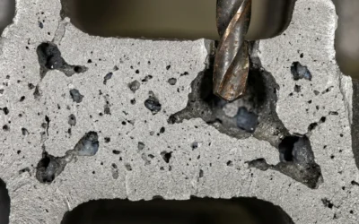
At the microscopic level, slag inclusions are non-metallic particles — oxides like Al₂O₃ and SiO₂ — trapped inside solidified steel where they don’t belong.
Refractory coatings erode under intense heat during pouring. That’s how inclusions form. In lost foam casting at temperatures between 1490–1510°C, Al₂O₃-based coatings break down. They shed spherical particles around 40–60 μm in diameter. Those particles don’t float out. They lock into the casting wall — sometimes going 2 mm deep into bores, top surfaces, and internal cavities.
The chemistry tells the real story:
-
In defect zones, aluminum content spikes above 7%. In individual particles, it can hit 32%.
-
Clean base iron sits below 0.1% aluminum.
-
Oxygen content reaches 11–28% in affected areas.
These oxide particles do two damaging things. They act as nucleation sites for MnS. They also become crack initiation points under load. So what starts as a contamination problem turns into a structural failure risk.
The cost is real. One brake caliper housing operation hit a 40% scrap rate — all from slag inclusions on machined surfaces. That rate made the entire production run nearly impossible to profit from.
Cause #1: High Oxide Content In Charge Materials — And How To Fix It
Rusty scrap is cheap. That’s the problem.
Foundries pull corroded stock into the charge to save money upfront — and pay far more on the back end. Rusted or moisture-bearing charge materials bring FeO, Fe₂O₃, and hydroxyl compounds straight into the melt. At steelmaking temperatures, those compounds don’t burn off. They dissolve into the steel bath and spike dissolved oxygen levels — before a single deoxidizer goes in.
More dissolved oxygen in the bath means more deoxidation products. That hits all three precipitation stages.
Three-Stage Oxide Buildup
The problem builds in sequence:
– Primary deoxidation products form during alloying and final Al addition
– Secondary products precipitate as steel cools from refining to liquidus temperature
– Tertiary products precipitate from liquidus through solidification
A cleaner charge compresses this cascade. A dirtier one amplifies it at every stage.
The inclusion types are well-documented:
– Al₂O₃ — angular, 1–5 μm, forms chains and strings; hardest on machinability
– SiO₂-based silicates — plastic inclusions that elongate during rolling, pushing anisotropic mechanical properties
– Spinel-type oxides (FeO·Al₂O₃, MnO·Al₂O₃) — show up in semi-killed or killed steel as non-equilibrium deoxidation byproducts
Fine inclusions under 1 μm are the hardest to remove. Full RH refining cuts them by just 0.85 per mm². Coarse inclusions above 1 μm are more manageable — 8.78 per mm² removed. The math is clear: stop small inclusions from forming early. Chasing them downstream doesn’t work.
The Fixes
Fix #1 — Scrap selection standards. Cut out corroded scrap. Use clean, low-oxidation stock with a controlled surface condition. A lower charge oxide load drops bath dissolved oxygen — before deoxidizers even enter the picture.
Fix #2 — Drying and de-rusting before charging. Moisture-bearing materials break down in the furnace and push oxygen into the bath. Dry everything before it goes in. Strip FeO/Fe₂O₃ scale from scrap surfaces before they hit the melt.
Fix #3 — Precise deoxidizer dosage. Too much deoxidizer creates surplus oxides. It stops being a solution and becomes an inclusion source. Calculate dosage based on steel grade. High-strength steel works best with Al; low-alloy grades can use Si or Mn. Add Al in slow, controlled steps — fast addition creates large Al₂O₃ clusters that are much harder to float out.
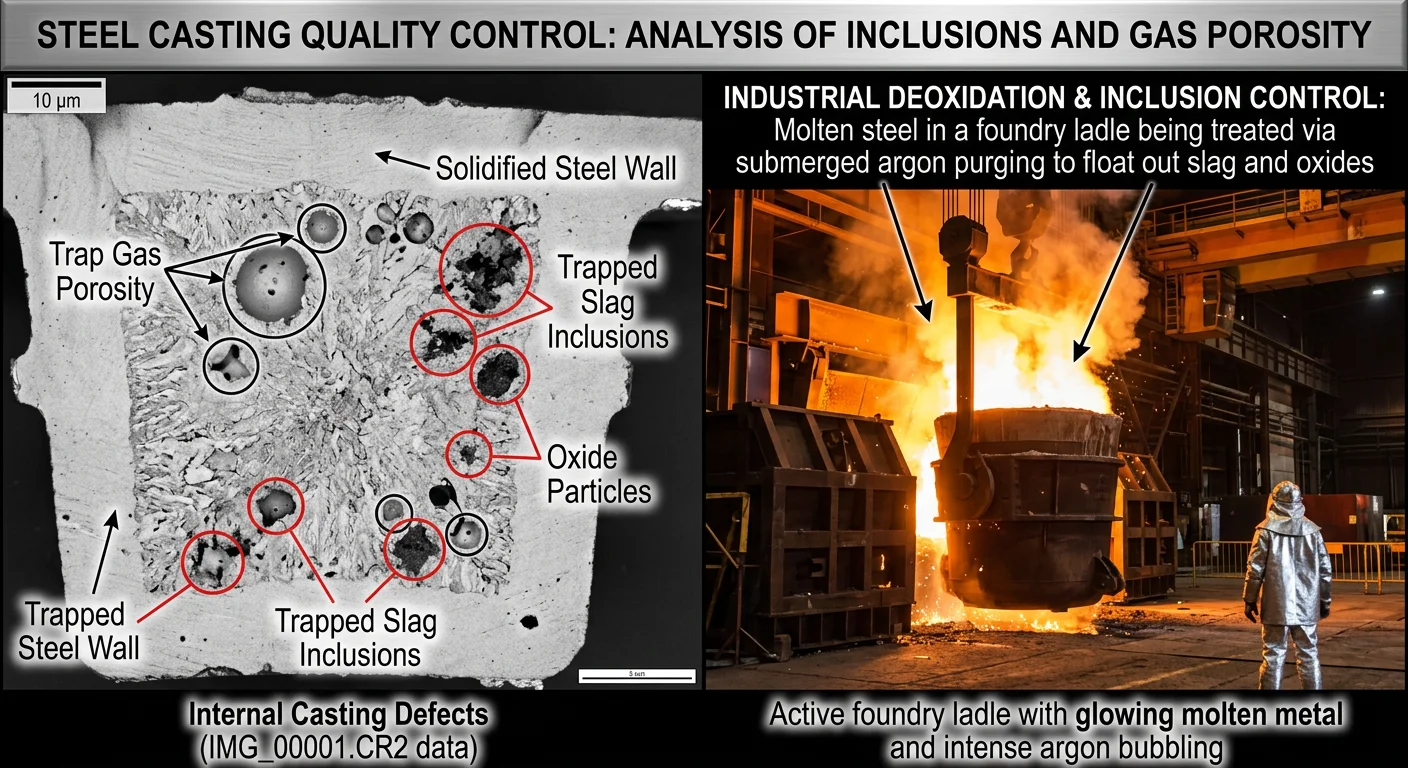
Fix #4 — Argon purging. Al₂O₃ has a contact angle of 144° with steel; SiO₂ sits at 115°. Both are unwetted — they latch onto argon bubbles and float to the surface. Small bubbles, soft purging, multiple purging elements, extended purging time: all of it lifts removal efficiency for charge-origin oxides.
Fix #5 — Calcium treatment for strict-grade steel. CaSi injection turns angular Al₂O₃ chains into spherical calcium aluminates — 12CaO·7Al₂O₃ or 3CaO·Al₂O₃ — that stay liquid at casting temperature. No nozzle clogging. No stress concentration from sharp angular inclusions locked into the casting wall.
Oxide control starts at the charge. Everything after that is damage management.
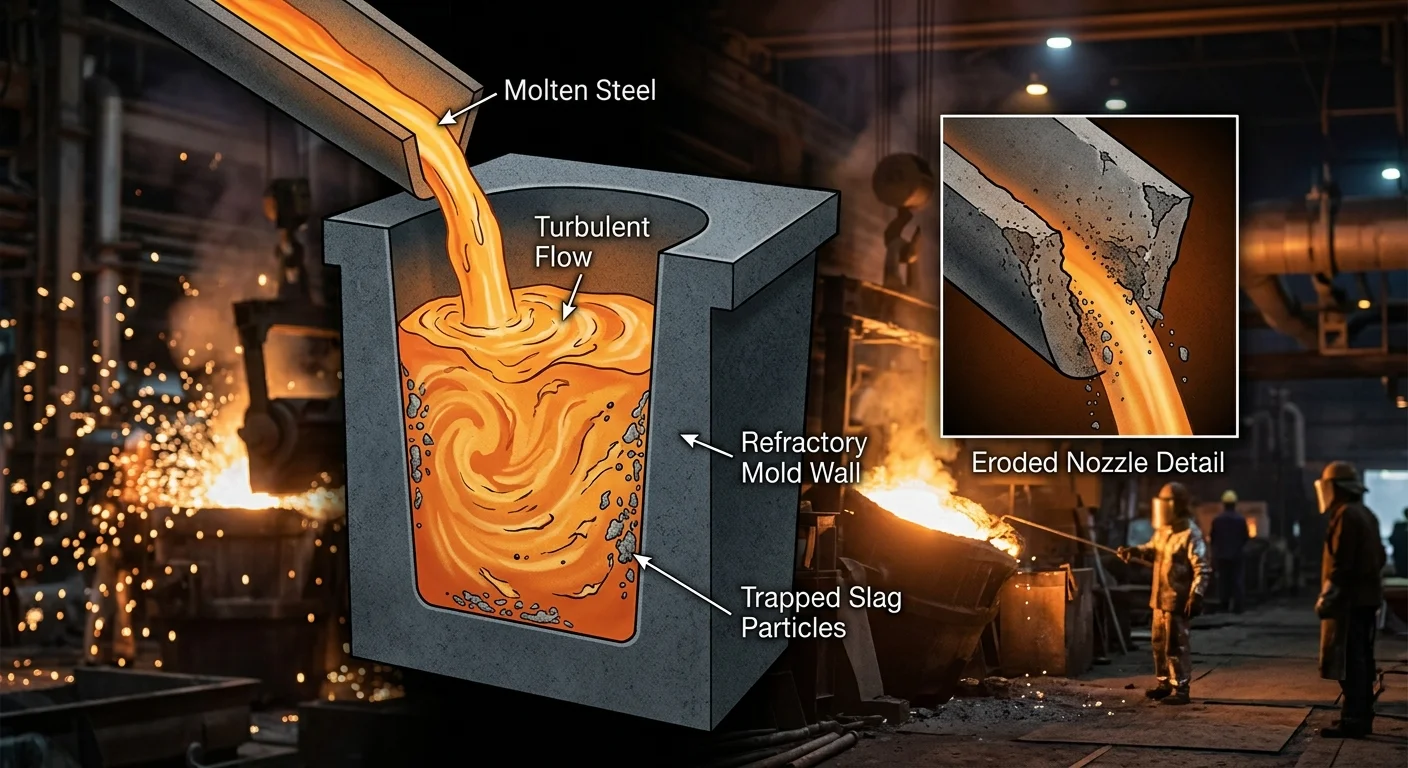
Cause #2: Turbulent Molten Metal Flow — And How To Fix It
Turbulence is a physical process. Once it starts, the melt cannot recover.
Molten steel enters the subentry nozzle (SEN) and hits the mold at high velocity. The flow breaks apart fast. Jets wobble off-axis. Swirl builds at the nozzle bottom. Velocity fluctuations spike near the top surface of the mold. That’s not a design flaw — that’s fluid mechanics behaving as it does at high Reynolds numbers. The real problem starts at the slag-steel interface.
Wall shear stress builds at the impingement zone. The k-ε turbulence model lets you calculate this. Newton’s viscosity law, applied at the interface, shows shear forces eating into the slag layer. Molten iron losses into the slag go up. Refractory surfaces and sand interfaces wear down under repeated impact. The slag particles that get trapped don’t show up on the surface. They lock into the casting wall and stay there.
Flow asymmetries in the lower mold region add more pressure to the system. Velocity fluctuations from both mold sides collide and push the instability further.
The Fixes
Fix #1 — Optimize the gating system.Bifurcated well-bottom nozzles with horizontal ports cut down on wobbling jets and swirl-driven turbulence at the source. Adjusting the gating ratio isn’t a cosmetic change — it determines where turbulent energy concentrates. Get this right, and you reduce the core problem before it reaches the mold.
Fix #2 — Control meniscus fluctuation.
Hold it within ±3–5 mm. Past that threshold, entrainment risk rises fast and becomes hard to manage.
Fix #3 — Place ceramic filters at the right points. Filters at the SEN exit or mold entry catch turbulent slag before it embeds in the casting wall. In near-wall and transition zones — Y⁺ below 500 — eddy capture efficiency jumps by 20%+ compared to mainstream placement. LES and URANS modeling shows an 80–95% velocity match with physical measurements. That gives you a solid predictive baseline before the pour starts.
Control the flow. The inclusions follow.
Cause #3: Inadequate Slag Skimming and Melt Treatment — And How To Fix It
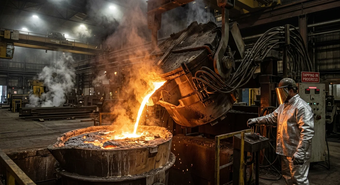
Slag doesn’t wait for a convenient moment to cause problems. It enters the ladle during the final tapping phase — often because the operator relies on visual judgment alone to call the cutoff. Metal flow stops. Slag follows. By the time anyone reacts, it’s already mixed in.
Three operational failures drive most of this:
-
Late visual cutoff — watching steel quantity by eye during the final tapping phase means slag enters the ladle before the furnace completes its tilt.
-
Delayed skimmer response — every second between tapping completion and mechanical skimmer deployment lets slag-metal mixing go deeper.
-
Poor covering agent application — skip this step or use the wrong material, and slag separation before secondary refining stays incomplete.
The Fixes
Fix #1 — Standardize the skimming sequence. Tilt the furnace on the cradle during the final tapping phase. Cut off slag the moment metal flow stops. Move the mechanical skimmer into position before you transport the ladle. Then apply a low-FeO, high-MgO covering agent to lock the slag layer in place.
Fix #2 — Control argon flow rate. Keep argon injection between 300–500 dm³/min through the porous plug. This builds a swirling gas-liquid column. That column lifts steel to the slag interface and pushes clean metal back to the bottom. Go past 600 dm³/min and the interface breaks down — steel splashes into slag instead of mixing through it cleanly.
Fix #3 — Match your approach to furnace type. Induction furnaces produce stable, lower-temperature slag. Argon stirring handles most of the separation work here. EAF operations run differently. CO bubbles, active foaming, and chemical splashing all make the skim harder to control. EAF slag needs N₂ lance splashing and tighter foaming control to stop inclusions from getting back into the melt.
Get the skim timing wrong, and no amount of downstream refining fixes it.
Cause #4: Contaminated Base Metal Or Charge — And How To Fix It
Charge contamination doesn’t announce itself. It shows up hidden — inside recycled scrap from battery plants, coating sludge from cold-rolling mills, acid-base residue that looks harmless until it’s already inside your melt.
The heavy metal profile is the real problem. Chromium-containing sludge from steel plate coating processes carries 3–12% chromium concentration. During storage, trivalent Cr³⁺ oxidizes into hexavalent Cr⁶⁺. XPS analysis confirmed 18.8% Cr⁶⁺ states in contaminated samples. Cadmium is worse. Acid-extractable Cd fractions hit 52% in some charge samples. It releases fast and hard under shifting pH conditions inside the furnace. Chloride contamination reached 20,448.4 mg/kg in documented charge material. That number alone should stop any procurement conversation cold.
Each contaminant hits melt chemistry in its own way. Together, they stack the odds against a clean pour.
The Fixes
Fix #1 — Verify incoming charge with XRD and XPS analysis. Visual inspection misses heavy metal speciation. Full stop. Lab analysis identifies Fe₂O₃ concentrations (documented at 45.5–51.9% in contaminated samples) and flags dangerous valence states before charge materials enter the furnace.
Fix #2 — Run acid-base washing on suspect scrap. This cuts chloride content in contaminated stock. It also removes surface-bound contaminants that visual screening won’t catch.
Fix #3 — Use high-temperature calcination where washing falls short. Washing handles a lot. Calcination handles what washing leaves behind — residual chloride levels that no rinse cycle can reach.
Fix #4 — Use BCR sequential extraction to rank charge risk. The method separates residual-state metals (low risk, above 65% in most cases) from mobile acid-extractable fractions. Those mobile fractions are the ones that threaten your melt. Cadmium’s RAC values run 44–52% — that puts it deep in the high-risk zone. Know that before it goes into the furnace.
Contaminated charge is a sourcing problem wearing a metallurgical mask. Fix it upstream.
Cause #5: Poor Pouring Techniques — And How To Fix It
The pour itself is where control either holds or collapses.
Speed, height, angle, timing — get any one of these wrong and you’ve handed slag a direct path into your casting wall. Turbulence doesn’t need much of an invitation. A pour that’s too fast, too high, or badly angled creates chaotic flow conditions. Those conditions drag oxide films and surface slag into the melt stream. Then solidification traps them in place.
What Poor Pouring Does
Molten steel entering the mold at the wrong angle or drop height hits the mold wall hard. That impact breaks the clean metal surface. Oxide films fold inward. Entrained slag — which was floating on top — gets driven down into the liquid pool. The faster and more erratic the pour, the deeper those inclusions travel before the steel solidifies around them.
The Fixes
Fix #1 — Control pour height. Higher drop distances increase turbulence at the point of entry. Keep pour height consistent. Aim as low as you can manage throughout the full pour sequence.
Fix #2 — Maintain a steady pour rate. Inconsistent flow creates pressure waves inside the mold cavity. A controlled, uninterrupted pour rate cuts out the surges that drive slag entrainment.
Fix #3 — Angle the pour with purpose. Direct vertical pouring at 0° maxes out impact turbulence. Adjust the tilt angle to guide metal along the mold wall rather than striking it head-on.
Sloppy pouring erases every upstream control measure you’ve built. The melt doesn’t forgive a bad entry.
Cause #6: Refractory Erosion And Poor-Quality Nozzles — And How To Fix It
Refractory materials don’t fail all at once. They fail one millimeter at a time — and by the time you notice, the damage is already inside your casting.
Chemical erosion is the main failure mode in steelmaking nozzles. It moves through three stages. First, inclusions contact the refractory surface. Then diffusion and partial liquefaction begin. Finally, bulk flow carries the degraded material into the melt stream. That eroded material becomes inclusion content. Simple as that.
The numbers tell you how fast this happens:
-
Doloma nozzles erode at 1 mm/hour under normal operating conditions
-
Graphite nozzles erode at 0.124 mm/s at the throat — 2.6× faster than tungsten
-
Tungsten nozzle inserts hold at 0.02–0.05 mm/s, making them far more stable under thermal load
Moisture makes everything worse. H₂O is 3× more damaging than CO₂ in driving nozzle erosion rates. Higher chamber pressure adds to this — more convective heat transfer, more aggressive surface reactions, faster material loss.
Once throat-area increase crosses 5%, the nozzle is no longer within safe design limits.
The Fixes
Fix #1 — Select nozzle material based on your actual operating temperature. Molybdenum performs best at lower flame temperatures. Tungsten holds up better under extreme thermal load. Cut graphite from high-pressure applications — full stop.
Fix #2 — Control moisture exposure. H₂O drives erosion at 3× the rate of CO₂. Pre-dry all refractory components before use. This step is non-negotiable.
Fix #3 — Specify coarse-grain tungsten over fine-grain. Arc-cast tungsten with a coarse grain structure resists thermal-stress fracture far better than fine-grain variants. It’s a material spec call that costs nothing extra at the sourcing stage.
Fix #4 — Monitor throat-area growth as a live quality signal. Don’t wait for a casting rejection to find out the nozzle has degraded past its working range. Measure it. Flag it at 5%.
Bad nozzles don’t just wear out — they contaminate every pour they touch.
Cause #7: Inadequate Deoxidation And Metallurgical Practices — And How To Fix It
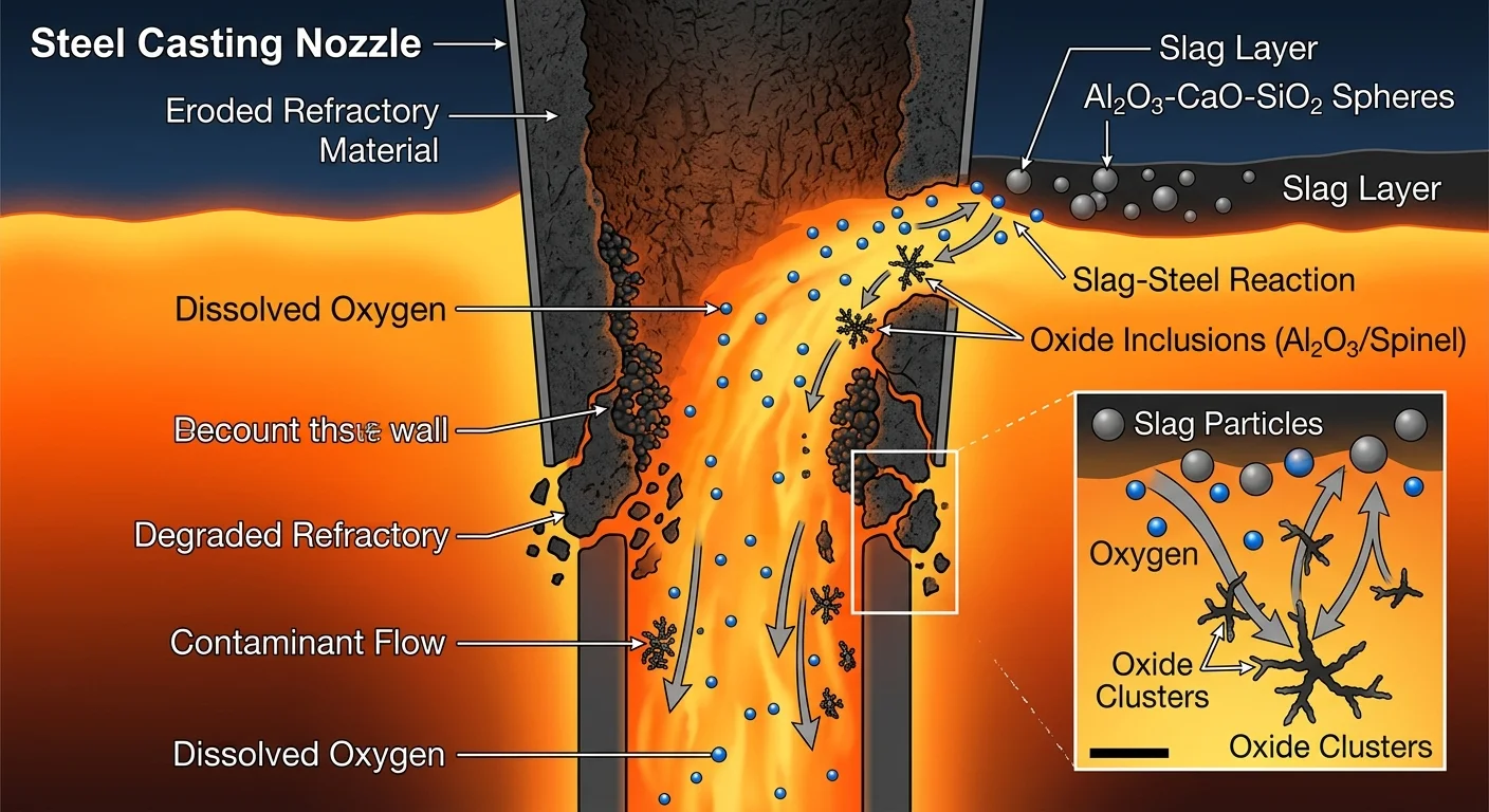
Dissolved oxygen is quiet. It doesn’t announce itself. It sits in the bath at 10–50 ppm and waits — then reacts with slag components to build inclusions you never planned for.
Aluminum additions that fall short of the 0.02% target shift the chemistry fast. Residual oxygen hits the CaO-SiO₂-Al₂O₃ slag system directly. That reaction generates secondary inclusions — Al₂O₃·CaO·SiO₂ compounds that build up to 5–10 vol% inside the steel. Spinel-type inclusions follow, sitting in the 0.5–5 μm range. The inclusion index climbs 20–50% before the pour even starts.
The sequence matters more than most operators think.
The Fixes
Fix #1 — Add deoxidizers in the right order, at the right time.
The sequence is non-negotiable: Mn (0.1–0.3%) first, then Si (0.2–0.5%), then Al (0.01–0.03%). Total addition: 0.5–1.0 kg/t steel. Add Mn and Si at tap. Hold Al until post-tap. Then stir for 5–10 minutes before moving to the next step. Skipping this order and dumping everything in at once causes uncontrolled oxide bursts. That’s not a recoverable situation.
Fix #2 — Run argon blowing with discipline.
Flow rate: 50–100 NL/min. Duration: 10–20 minutes. That combination pushes slag flotation and pulls inclusion area percentage from 0.015% down to 0.005% — a 40–60% reduction. That’s not a small gain. A casting either passes inspection or it doesn’t. This is what decides it.
Fix #3 — Use LF furnace refining when the grade demands it.
Pre-LF inclusion index runs 15–25. Post-LF, it drops to 5–10. That’s a 65% reduction. Parameters: hold at 1550–1580°C, argon stir for 20–30 minutes, feed Ca-Si wire at 1–2 kg/t. Total oxygen drops from 30 ppm to 10 ppm. Non-metallic inclusion area falls below 0.002%.
Deoxidation isn’t a checkbox. Every shortcut leaves oxygen in the bath — and oxygen finds its way into your casting wall.
How To Build A Systematic Slag Inclusion Prevention Protocol
Seven causes. Seven points of failure. Each one can wreck a production run on its own — and when they stack, the damage adds up fast.
Foundries that hit slag scrap rates below 0.1% aren’t lucky. They run a protocol. Every stage of production has defined checkpoints, measurable targets, and a clear rejection threshold. Here’s how to build that system.
Stage 1: Melting Controls
Start at the raw material level. Pig iron enters with certified mill test reports — oxygen below 0.2 wt.%, nitrogen below 0.01 wt.%. Every piece of scrap and returns needs 100% visual inspection plus shot blasting before it goes near the furnace. No exceptions.
Run double slagging. Pull floated slag after the initial superheat. Pull it again before tapping. Hold superheat at 150–200°C above liquidus. Don’t let melt holding time drift past 30 minutes.
Stage 2: Pouring Controls
Dry-preheat ladles to 800–1000°C. Keep hold time after preheating under 5 minutes — oxide pickup climbs fast past that window.
Lock pour parameters in place:
– Superheat at 100–150°C above liquidus
– Pour time under 20 seconds per cavity
– Liquid level fluctuation under 5 mm
Use slag traps and shrouded nozzles. Push the nozzle 50–100 mm below the meniscus to cut air entrainment.
Target protection slag viscosity at 0.2–0.5 Pa·s at pour temperature. That keeps it fluid enough to float inclusions, but stable enough not to stick.
Stage 3: Verification
Pour micro-cleanliness test bars alongside production. Run image analysis. Check that inclusion area fraction stays below 0.5%. Then calculate your Cleanliness Index:
CI = 1 − (Inclusion Area % ÷ Total Area %) > 0.995
Anything below 0.995 stops the run.
Back that up with NDT. Ultrasonic testing covers 100% of critical sections. Reject any piece with echo amplitude above 20% of reference. Magnetic particle testing catches surface and subsurface slag scars down to 0.5 mm after shot blasting.
The target: UT/MT reject rate below 1%. Foundries that run this full protocol drop from 5–10% NDT scrap down to near-zero. Fatigue strength in finished castings goes up 15–20% on average, with tighter scatter across the production run.
The protocol in six steps:
-
Qualify suppliers — certified pig iron with O below 0.2%
-
Pre-treat everything — ladle at 1000°C, scrap blast-cleaned
-
Double skim the melt — superheat controlled, hold time capped
-
Control inoculation — 0.3% late-stream low-oxygen ferrosilicon
-
Lock down pour parameters — slag traps, under 5 mm fluctuation
-
Verify before you ship — CI above 0.995, 100% UT on high-integrity parts
Track scrap rate by batch. The number climbs — the protocol tells you where to look.
How To Identify Slag Inclusions vs. Other Casting Defects
Misidentify the defect, and every fix you apply points in the wrong direction.
Slag inclusions have a clear visual signature. On the cope side of the casting, they show up as ribbon-like or pocket-shaped non-metallic pockets — small, deep, with irregular foreign particles stuck in the surface. Gas porosity looks different: spherical, rounded holes with smooth, shiny walls. Shrinkage porosity is also different: jagged, branching voids packed into thick sections and last-to-freeze zones. Sand inclusions have sharp, angular edges and a gritty texture. Slag oxides are smoother.
On fracture surfaces, slag appears as brittle, glassy clusters. These sometimes stretch into ribbons along the break. Gas porosity leaves clean, round voids. Shrinkage leaves feathery, branch-like structures with no glassy phase. The difference is clear once you know what you’re looking at.
Visual inspection not enough? SEM-EDS confirms it:
-
Polish the cross-section to expose the defect
-
Use SEM imaging to check shape — ribbon or pocket form points to slag
-
Run EDS spectroscopy and check for oxide compounds: SiO₂, CaO, Al₂O₃, MgO above 10–20% non-metallics
High-viscosity slag trapped inside the casting needs microstructure analysis to detect. It cuts tensile strength by 10–30% — and none of that damage shows on the surface.
On the shop floor, use this fast-classification framework:
|
Defect |
Location |
Visual Cue |
Key Variable |
|---|---|---|---|
|
Slag |
Cope-side, deep |
Ribbon/pocket shape |
Low pour temp, slow pour, high O₂ |
|
Sand |
Surface |
Gritty, angular |
Low bentonite (<5%) |
|
Gas |
Random |
Round pinholes |
Mg vapor, air contact |
|
Shrinkage |
Centers/risers |
Feathery voids |
Feeding failure |
One camshaft operation tracked this in detail. With automatic pouring, slag and pinhole scrap exceeded 50%. They switched to manual ladles — same sand, same iron — and scrap dropped below 5%. The defect tracked with pour method, not material. That’s slag. This pattern shows up in 90% of cases with that profile.
For NDT confirmation, you have three solid options. Dye penetrant covers surface defects. Radiography separates internal slag (irregular density) from round porosity. Ultrasonic testing catches subsurface slag scar clusters before machining brings them to the surface.
Conclusion
Slag inclusions don’t happen by chance — they follow a pattern. And that’s good news. Patterns can be fixed.
You’ve now identified the 7 common causes of slag inclusions in steel castings:
-
Oxidized charge materials
-
Turbulent flow
-
Poor skimming
-
Contaminated metal
-
Sloppy pouring practices
-
Eroded refractories
-
Weak deoxidation
Each one has a clear, workable solution.
But knowing the causes isn’t enough. The foundries that produce clean, defect-free castings aren’t just reacting to problems. They’ve built prevention into their process from day one.
So here’s your next move: audit your current workflow against each of the seven causes. Find your weakest link. Fix that first.
One targeted improvement leads to a cleaner melt. Fewer rejects follow. Rework costs drop. Your production floor starts running the way it should.
The slag stops where the discipline starts.