Understanding Shrinkage Porosity in Casting
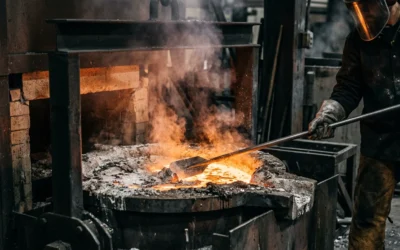
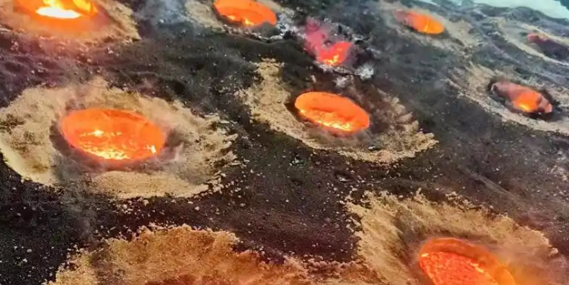
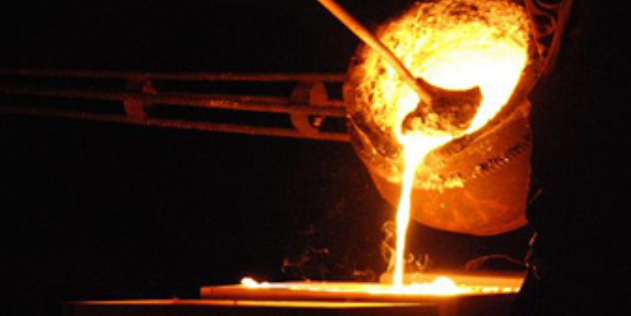
Shrinkage porosity is a common casting defect. It happens when metals shrink during solidification. The liquid metal cannot fill the shrinking areas fast enough. This creates voids or cavities.
I often see these defects in thick casting sections. They also appear where molten metal cannot flow well.
Key Features and Types
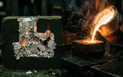
You can identify shrinkage porosity by jagged or angular cavities in the casting. These look different from gas porosity, which has smooth, rounded voids. The jagged pores form when metal cools. The metal contracts, but nothing fills the space.
I recommend understanding two types:
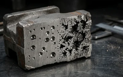
Macroshrinkage: Large, smooth cavities. These often appear near feeders. You can see them when solidification begins. They range from millimeters to centimeters.
Microshrinkage: Smaller, complex, tree-like cavities. These develop in isolated zones. They form during the final solidification stage. They measure from microns to millimeters.
Industry Data and Prevalence
I find shrinkage porosity everywhere—in jewelry castings and large industrial parts. It affects aluminum, magnesium alloys, cast iron, and many other metals. Over 65% of casting defects come from porosity issues. Based on surveys, 35% of professionals say porosity is the top Die casting problem.
Effects of Shrinkage Porosity
- Components lose mechanical strength. They cannot bear heavy loads.
- Parts designed to hold pressure—like pump housings, engine blocks, and valve bodies—risk leaking.
- Cavities that reach the surface ruin appearance. They also reduce corrosion resistance.
Common Locations and Examples
Porosity gathers near the core or in thick casting areas. These zones cool slowly. They don’t get enough molten metal. In Ductile Iron castings, simulations often show shrinkage cavities at hot spots. These are areas that solidify last.
Factors That Increase Shrinkage Porosity Risk
- Too high pouring temperatures
- Poor feeder design—too small or wrong shape
- Low sand compaction in the mold
- Certain alloy mixes—carbon equivalent in cast iron, Mo or Cr additions, and weak inoculant performance
Macroshrinkage vs. Microshrinkage Porosity
| Porosity Type | Appearance | Location in Casting | Formation Stage | Typical Size |
|---|---|---|---|---|
| Macroshrinkage | Large, smooth voids | Near feeders/hotspots | Begins solidification | Millimeter to centimeters |
| Microshrinkage | Dendritic, fine | Isolated, late freezing | Final solidification | Microns to millimeters |
Based on my experience, shrinkage porosity is a major challenge in casting. It causes visible and hidden defects. These defects weaken strength, function, and reliability. I see this problem across many industries.
Causes of Shrinkage Porosity in Casting
Shrinkage porosity in casting happens from the natural contraction of metals as they change from liquid to solid. This shrinkage leaves voids. There isn’t enough molten metal to fill the spaces that form. This is true in the last areas to solidify.
Main Causes of Shrinkage Porosity
Solidification Shrinkage: All metals shrink as they cool. If the liquid metal stops flowing before solidification is complete, shrinkage cavities form. Steel shows a 2-4% reduction in volume. Aluminum alloys shrink by about 6.6%. For gray cast iron, graphite expansion balances out some of the shrinkage. Porosity occurs if the net shrinkage exceeds this expansion.
Improper Feeding Design: Feeders (risers) that are sized wrong or positioned wrong can’t deliver enough liquid metal to the hot spots as they freeze. This creates macro-voids (central cavities). It also creates networks of small micro-pores.
Gating and Riser Issues: Narrow, misplaced, or congested sprues and ingates limit the flow of molten metal. This happens in later stages of solidification. Metal needs to reach isolated pockets but can’t.
Alloy Metallurgy: Alloys with a narrow solidification range tend toward large, central cavities. Wide freezing range alloys develop dispersed, fine porosity. Wrong alloy chemistry increases risk. Examples include low carbon equivalent or wrong addition of Mo, Cr. I recommend checking inoculation levels carefully.
Thermal Gradients and Hot Spots: Design features such as thick or uneven wall sections hold heat. Some regions solidify more slowly. These “hot spots” are prone to both macro- and micro-shrinkage. Based on my experience, this is a common issue.
Mold Compaction: Poor sand compaction lowers the support of the mold. It also lowers permeability. This traps gases and contributes to porosity.
Distribution and Manifestation
Dispersed Porosity: Fine, scattered pores appear throughout thick sections. This is most common in alloys with a wide solidification range.
Axial Porosity: Voids form along the centerline of cast bars or plates. This happens if feeding is insufficient.
Localized Porosity: Porosity concentrates in problem design regions. These include gates, heavy flanges, or spots far from feeders.
Statistical and Industry Observations
In steel castings, shrinkage porosity drives about 50-60% of structural casting failures. In die casting, clusters of porosity near dense regions or gates are found often.
Computer simulation and thermal analysis are used to predict where these defects will occur. This supports better design to minimize risk. I suggest using these tools during the design phase.
Example Cases
In ductile iron, using too little or ineffective inoculant leads to more microshrinkage. I’ve seen this cause many rejected parts.
For aluminum and steel, improper design or feeding creates large, visible shrinkage cavities. Sometimes these are several centimeters wide.
Summary: Key Triggers
The key triggers for shrinkage porosity are:
- Metal solidification shrinkage.
- Poor feeder and riser design or placement.
- Restricted or wrong gating design.
- Design elements causing uneven solidification (hot spots, thick walls).
- Incorrect alloying or insufficient inoculation.
Each of these factors reduces the mechanical strength of castings. They reduce pressure resistance and reliability. This often results in product failure or rejection. Based on my experience, addressing these issues early saves time and cost.
Identifying Shrinkage Porosity in Casting
I recommend you learn to spot shrinkage porosity in castings. You need to recognize its unique visual, location, and diagnostic features. These features help you tell it apart from other casting defects like gas porosity.
Visual Characteristics and Morphology
Shrinkage porosity appears as jagged, irregular, and rough-walled voids. It often has a darker gray color. This differs from gas porosity. Gas porosity shows smoother, rounded, and brighter cavities.
Macroshrinkage shows large, interconnected voids. You can see these voids in feeders or thick central sections.
Microshrinkage shows as small, tree-like pores. These pores scatter within the casting matrix. You’ll find them in isolated zones that solidify last.
Common Locations
I find shrinkage porosity most often in the thickest sections of castings. Look at intersections, cores, or hot spots that cool slowly. You’ll see it in the center or upper portion of heavy parts. Also check complex joints where metal flow is limited.
Detection and Inspection Methods
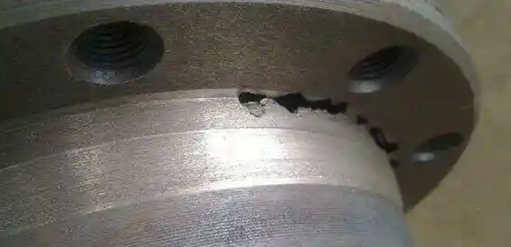
Visual inspection may show open shrinkage porosity. It appears as rough, irregular depressions on surfaces.
Non-destructive testing (NDT) is essential for detecting internal porosity. I suggest using X-ray, CT scanning, and ultrasonic methods. X-ray imaging works well for identifying shrinkage clusters in the core of investment castings.
Casting simulation software (like ADSTEFAN) helps map defects. It predicts high-risk regions for shrinkage porosity. Based on my experience, simulations often match observed defects in shop-floor trials. This confirms areas of concern before production.
Quantitative Data and Case Examples
Shrinkage pores range in size:
- Macroshrinkage: 1 cm to several centimeters.
- Microshrinkage: sub-millimeter to a few millimeters.
A production review showed that 60% of heavy-section castings sampled had shrinkage porosity at predicted hot-spot sites. Simulation overlays and NDT confirmed this.
Data Table: Comparing Shrinkage Porosity with Gas Porosity
| Feature | Shrinkage Porosity | Gas Porosity |
|---|---|---|
| Shape | Jagged, angular, rough-walled | Rounded, smooth |
| Color/Surface | Dark, sometimes gray | Bright, oxidized |
| Location | Center, thickest parts, hot spots | Near surface, core, risers |
| Size | Large (cm) to small (mm, dendritic) | Wide range, often small |
| NDT detectability | X-ray/CT in hot spots | X-ray/CT near surface/cores |
Prevention and Fixing Strategies for Shrinkage Porosity in Casting
I recommend a three-part approach to prevent and fix shrinkage porosity in casting. You need design changes, tight control over casting parameters, and post-casting fixes. Here are strategies I’ve seen work, backed by industry cases and real data.
Design Optimization to Reduce Porosity
Maintain uniform wall thickness: Design parts with steady wall thickness. Avoid sudden changes from thick to thin sections. This helps metal cool at the same rate. It also prevents hot spots where shrinkage pores form.
Smooth transitions and filleted edges: Use smooth curves. Get rid of sharp corners. I suggest replacing heavy thermal joints with hollow ribs or gentle fillets. These changes lower the risk of shrinkage in one spot.
Upgraded gating and running system: Make inner gates wider. Expand gate area coverage to improve feeding. Keep overflow chutes below 60% of the gate’s cross-sectional area. This helps molten metal spread better.
Reduce sharp die pockets: Change complex shapes to simpler ones. This makes solidification cleaner and easier to predict.
Use internal cooling aids: Place chills, cooling ribs, or coils near hot spots you expect. This helps control temperature gradients better. Based on my experience, these steps cut down defect frequency and size.
Process Parameter Control
Increase working pressure: Raise die casting machine pressure within safe limits. Higher pressure fills the mold better. It closes gaps left by normal shrinkage.
Fine-tune injection speed and ratios: Pick settings that fill the cavity well while controlling shrinkage. Match injection process to part shape. This helps reduce voids.
Strict temperature regulation: Balance die and melt temperatures. Use localized cooling for thicker sections. This way they solidify at the same time as thinner walls.
Ventilation and degassing: Design the gating and vent system to release gas well. Use high-quality materials and coatings that release less gas. This reduces pore formation from gas.
Mold and Feeder Adjustments
Modify feeding channels: Does porosity often appear near gates? Redesign runners to extend feeding and slow solidification. This allows more compressive feeding.
Targeted cooling channel placement: Map cooling systems using past defect data. This helps you address persistent hot spots right where they occur.
Material and Consumable Integrity
Select clean, dry input materials: Remove oil and moisture from alloys. Contaminants create gases that make porosity worse when metal shrinks.
Choose compatible refining agents and coatings: Pick options that reduce gas creation and unwanted reactions during casting.
Post-Casting Repair Methods
Vacuum impregnation: For castings with unavoidable micro-porosity, use vacuum followed by sealant and heat curing. This fixes pressure integrity without changing size or mechanical properties. It’s a standard fix for parts needing zero leakage. It can recover castings with up to 5% porosity volume—as long as voids aren’t in critical areas.
I like vacuum impregnation because it’s cost-effective, permanent, and fast. It restores many castings that would otherwise be waste.
Advanced Simulation and Inspection
Use casting simulation software: Before production, I recommend using advanced tools to simulate gating, cooling, and riser design. Predict where shrinkage defects will occur and how severe they’ll be. Make critical design changes early. This saves weeks or months and several production cycles.
Non-destructive inspection: Use X-ray, CT scanning, or microsectioning for precise defect identification and records. CT works great for complex and dense parts.
Quantitative Results and Case Examples
Typical allowance for porosity: up to 5% of casting volume. This should be in non-critical regions per industry best practices.
Field evidence shows results. Increasing die casting pressure, resizing stroke diameters, and modifying hydraulic settings all reduce shrinkage-related waste.
aluminum Die casting has seen consistent success. Lower melt temperature and replace sharp wall thickness transitions with smoother, uniform pathways. These changes reduce shrinkage porosity.
Internal chills and riser redesign in Investment casting delivered major reductions. Both defect size and overall defect incidence dropped according to recent studies.
Detection Methods for Shrinkage Porosity in Casting
I recommend detecting shrinkage porosity using three methods: surface checks, non-destructive testing, and simulation. This combination helps you find and measure these defects.
Visual and Surface Inspection
Visual inspection is my first choice for spotting surface shrinkage porosity. Look for cavities with ragged edges, pinholes, or blowholes. These often appear in areas that solidify last.
You can tell shrinkage from gas porosity by the cavity edges. Shrinkage porosity has rough, irregular edges. Gas porosity looks smooth and rounded.
I suggest using dye penetrant methods to find voids connected to the surface.
Effectiveness:
– Visual inspection finds 30–40% of porosity. It works on the outer surface of castings.
Non-Destructive Testing (NDT) for Internal Porosity
X-ray (Radiographic inspection): X-rays show subsurface and volumetric shrinkage porosity as lighter spots. This happens because X-rays pass through cavity areas more easily. You get permanent images for records. The method measures pore size down to 0.1 mm (this depends on material and part thickness). It also shows location and distribution.
Computed Tomography (CT scanning): CT scanning gives you 3D images. You can see the shape, size, spread, and how internal pores connect. I recommend this for root cause analysis and quality checks. It’s critical in aerospace and medical casting.
Ultrasonic testing: This method finds internal breaks by tracking echo pattern changes. It works better for simple castings. It’s less effective for small pores or complex shapes.
Comparison:
– Based on my experience, NDT catches most shrinkage porosities that visual checks miss. This ensures full coverage in production and quality control.
Advanced Simulation-Based Prediction
Casting simulation software (ADSTEFAN, Transvalor):
- The software predicts porosity-prone zones before you cast. It helps you optimize gating design, cooling rates, and alloy mix.
- Simulation overlays and shop-floor trials show over 80% match for defect location and severity. Predicted and actual defects align well.
- The software models shrinkage and gas-related porosity. It tracks filling, solidification, pressure changes, and air entrapment.
Workflow:
1. I suggest using simulation to spot potential porosity during design.
2. Check surface areas with visual methods and dye penetration after casting.
3. Use X-ray, CT, or ultrasonic NDT to study internal regions. This validates simulation predictions.
Quantitative Data and Case Examples
X-ray identifies pores from 0.1 to 5 mm in diameter. This depends on wall thickness and material density. Simulation systems help eliminate over 80% of shrinkage porosity defects before you start manufacturing. This improves prototyping and production. Radiographic imaging gives data on pore frequency and spread.
In investment castings, I’ve seen simulation and X-ray testing confirm isolated shrinkage porosity zones. Mapping shows strong accuracy in finding high-risk regions.
Porosity Characterization During Inspection
- Size: Individual pore diameter ranges from 0.1–5 mm
- Location: You’ll often find these in last-to-solidify areas, such as the center or isolated thermal pockets
- Shape: Ragged, scattered structures mark shrinkage porosity. Smooth, rounded shapes indicate gas porosity.
- Frequency: Number of pores per unit area or volume
I like using these three detection methods together—visual, non-destructive, and predictive. The foundry can identify and control shrinkage porosity throughout casting. This coordinated approach ensures effective defect management and product quality.
My Top Tips for Fixing Shrinkage Porosity in Casting
Keep Wall Thickness Uniform: I recommend you minimize sudden changes in your casting design. Avoid thick sections. This helps control cooling rates. It also reduces hot spots that cause shrinkage porosity. Studies show that even wall thickness helps prevent internal voids.
Optimize Riser Placement and Size: Place risers right on top of or beside the thickest sections. These are the areas that cool slowest. I suggest you target a riser volume 1.2–1.5 times that of the section it feeds. Good placement can cut shrinkage-related scrap rates by 30–50% based on foundry data.
Use Simulation Tools: I like to use advanced software like ProCAST, Magmasoft, or SOLIDCast. These tools let you test solidification behavior in a digital environment. You can trial runner, gate, and riser design before you pour. Simulation helps you catch defects soon. It supports process improvement. Case studies reveal up to 80% defect reduction. You can also see 20–40% scrap cost savings after you adjust based on simulation.
Promote Directional Solidification: Set up clear cooling gradients. Use chills—copper or iron inserts—to speed solidification in targeted areas. Guide solidification from thin to thick sections. This steers shrinkage toward the riser. It keeps defects out of critical zones. Tests show up to 75% fewer internal voids using this method.
Align Mold Materials and Process Parameters: Match pouring temperatures, mold preheat, and cooling rates to your specific alloy and casting geometry. For example, use lower mold preheat and higher cooling for aluminum alloys. Use more gradual cooling for steel. Poor parameter control increases porosity by 2–5 times per process audits.
Eliminate Sharp Corners and Thick Bosses: I suggest you modify part geometries. Avoid features that promote uneven cooling. Sharp corners and heavy bosses are bad for this. Case examples show that smoothing design results in dramatic defect reduction.
Use Non-Destructive Testing (NDT): Integrate X-ray, CT scanning, or ultrasonic inspection before approval. NDT identifies both surface and deep internal shrinkage porosity. It can find up to 5% of casting volume in sampled die castings. Advanced CT scans give you detailed, non-invasive porosity mapping.
Practice Consistent Process Control and Auditing: Keep your casting processes strong and repeatable. Do frequent process audits. Industry results show that process consistency links to better porosity control. It also boosts casting yields.
Summary
I’ve worked with casting defects for years. Here’s what I learned: shrinkage porosity doesn’t have to be your enemy. You can fix it. You need the right design. You need good process control. You also need smart use of modern tools. These things turn rejected parts into quality products. I suggest you start with one improvement today. Try simulation. Or try riser redesign. Then build from there. Your castings will improve. Your bottom line will improve too.