Key Differences Between Porosity and Shrinkage Cavities
Porosity and shrinkage cavities are two different casting defects. They affect metal castings in different ways. I recommend understanding their differences for better defect analysis and prevention.
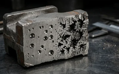
Porosity in castings means many small, rounded or oval holes. These holes come from trapped gas. For example, hydrogen dissolves in molten aluminum. It forms bubbles during cooling. Scattered throughout the casting. You can see it inside the casting (via destructive testing or CT scanning). Porosity decreases mechanical strength. It causes leakages. This is a major concern for high-pressure or air-tight components such as hydraulic parts.
Shrinkage cavities are larger and more irregular voids. They form when metal contracts. Insufficient liquid metal feeds the last areas to solidify. Found after sectioning or by X-ray imaging. They are located at casting centers or heavy junctions. This happens at thicker sections or centers of castings. Shrinkage cavities introduce serious structural weakness and stress concentration. They can lead to the rejection of critical load-bearing castings.
Visual and Physical Characteristics
Porosity:
- Shows as small, rounded holes (diameters from 0.05 mm up to 2 mm).
- Spreads randomly within the casting or along upper surfaces.
- You can see them after sectioning, machining, or using advanced inspection methods.
Shrinkage cavities:
- Larger in size. Often several millimeters to several centimeters depending on casting design.
- Irregular, rough, or branched shapes (like tree roots).
- Found in the center, thickest sections, or last areas to solidify near risers or hot spots.
Mechanism of Formation: Porosity vs. Shrinkage Cavities in Castings
I believe understanding how these defects form is key to spotting and stopping them. Porosity and shrinkage cavities come from different physical processes. Each has distinct traits and causes that affect casting quality.
Formation of Porosity in Castings
Primary Cause: Trapped gases—like hydrogen, air, or moisture—cannot escape from molten metal before it hardens.
Gas Sources:
- Hydrogen dissolves in molten aluminum.
- Air mixes in during rough pouring.
- Moisture reacts with metal at high heat.
Formation Process:
- Metal cools, and gas solubility drops fast.
- Extra gas creates bubbles. This leads to round or spherical pores through the casting.
Types of Porosity:
- Blowholes: Large gas pockets, often just under the surface.
- Pinholes: Tiny, scattered gas bubbles.
Influencing Factors:
- Poor mold venting.
- Not enough degassing before pouring.
- High pouring temps or wet molds.
Example: In die-cast aluminum, bad venting creates clusters of small, round holes just under the casting surface.
Formation of Shrinkage Cavities in Castings
Primary Cause: Metal contracts when it hardens. If molten metal does not feed the last sections to solidify, voids form.
Solidification Dynamics:
- Outer layers harden first.
- Inner, thicker parts harden later. They need a steady flow of liquid metal to fill the space left by contraction.
Cavity Characteristics: Shrinkage cavities are often large, uneven, and V-shaped or branching. They appear at hot spots, thick sections, or central areas—the last to cool.
Concentrated vs. Scattered Shrinkage:
- One big cavity = concentrated shrinkage.
- Many smaller voids = shrinkage porosity.
Influencing Factors:
- Bad riser (feeder) design.
- Low pouring temperature.
- Too much thickness without good directional solidification control.
Example: In steel castings with thick hubs, a large, deep void in the center often shows a classic shrinkage cavity from poor feeder placement.
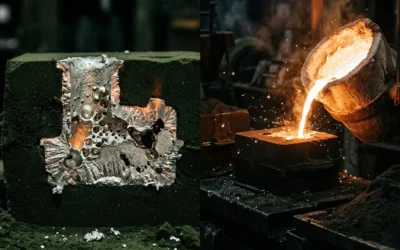
Illustrative Case Example
- Porosity: A cast iron flywheel shows many round holes in radiographs. This is a classic sign of gas-related porosity. Damp molds and rough metal flow cause it.
- Shrinkage: Cutting the same casting open shows a large, jagged central void at the hub. This marks a shrinkage cavity from not enough feeding during metal contraction.
How to Spot Porosity and Shrinkage Cavities in Castings
I recommend learning to tell apart porosity and shrinkage defects in castings. This skill matters for quality control. Technicians use visual clues and tests like radiography to diagnose problems. This prevents casting failures.
Key Visual Features
Porosity (Gas-Based Defects)
Smooth, Rounded Appearance: Porosity defects look like smooth, rounded holes or voids. They resemble air bubbles trapped in metal.
Common Types:
- Pinholes: Tiny, clustered pores. You can see them just under or at the surface.
- Blowholes: Larger, round cavities. Sometimes they hide inside. X-rays can detect them.
- Blisters/Open Holes: Surface-raised, round or oval marks. Open holes break through the casting surface.
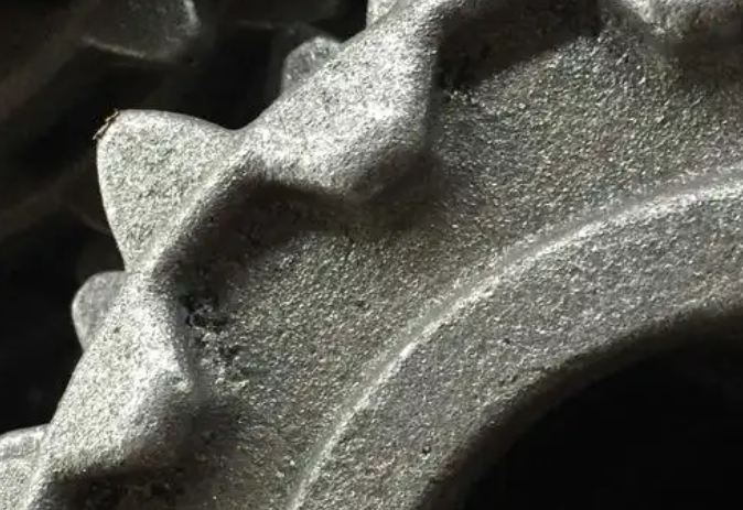
Distribution: Porosity scatters across the casting. It spreads out. You often find it in lighter and upper areas.
Surface Texture: Areas with porosity appear smoother than those with shrinkage.
Examples:
- Under a microscope, the metal surface looks like a sponge. It has many small, rounded cavities.
- Visual or X-ray inspection shows smooth-edged dark areas.
Typical Size: Gas porosity ranges from 0.5–5 mm in diameter.
Shrinkage Cavities
Jagged, Irregular Shapes: Shrinkage cavities differ from porosity. They show jagged, angular, or dendritic edges.
Common Types:
- Open Shrinkage (Pipes): These break through the surface at hot spots or riser locations. They have caved-in, angular outlines.
- Closed/Internal Shrinkage: Jagged or dendritic cavities form inside the casting. You can see them under low or high magnification.
- Sponge/Filamentary Shrinkage: Thin, irregular voids or lines. They may stretch across sections.
Location: Shrinkage defects gather in specific spots. They form at last-solidifying sections, thick-to-thin transitions, or near risers.
Surface Signs: These may appear as caved-in pipes, dips, or open holes. Machined surfaces can show hidden internal shrinkage after you cut into them.
Examples:
- X-rays display shrinkage as regions with sharp, jagged boundaries.
- Defects may look fine after machining. But they will leak or fail during pressure tests.
Typical Size: Shrinkage cavities can reach several centimeters. They appear irregular or pipe-like. They have sharp, angular profiles.
How to Identify Defects
- Visual Inspection: Rounded, spread-out voids mean porosity. Jagged, localized cavities mean shrinkage.
- Surface Location Check: Porosity distributes randomly. Shrinkage occurs at thick sections or hot spot locations.
- Sectioning/Microscopy: Rounded “shadow” cavities confirm porosity. Elongated, jagged voids signal shrinkage.
- X-ray Testing: Smooth-edged dark spots indicate gas holes. Jagged, angular darkness shows shrinkage cavities.
Distribution Patterns of Porosity and Shrinkage Cavities in Castings
I find that defect spread patterns in castings give us clear clues. They help us tell shrinkage cavities apart from porosity. This matters for finding root causes and controlling quality.
Typical Distribution Patterns
Shrinkage Cavities: They appear in the last areas to solidify. Look near risers, at gating systems, or where thick sections meet thin ones. I see them in complex castings or those with poor feeding. Heavy cross-sections and intersections are common spots. In plates and columns with uniform sections, axial cavities develop in the center. They are large, irregular, and grouped together. The interiors are rough with dendritic textures.
Dispersed Shrinkage Porosity: These appear as fine, microscopic pores. They spread through thick sections or areas that cool down slow. I recommend checking alloys with a wide crystallization temperature range. They are common there.
Axial Porosity: These form along the central axis of long structures. Think bars, plates, or columns. They result from poor feeding to the centerline during solidification.
Gas (Hydrogen) Porosity: These scatter throughout the casting volume. The pores are smooth, rounded, and not tied to one region. You can see them after machining or breakage.
Characteristic Distribution Table
| Defect Type | Typical Location | Shape/Pattern | Example Structures |
|---|---|---|---|
| Shrinkage cavity | Last to solidify, near riser/gating, thick-thin junctions | Grouped, large, irregular | Heavy cast areas, complex geometries |
| Dispersed shrinkage porosity | Uniform in thick sections | Spread out, fine | Thick sections, slow-cooled alloys |
| Axial porosity | Centerline of plates, bars, columns | Long, along axis | Columns, large plates |
| Gas/hydrogen porosity | Throughout casting volume | Rounded, uniform | Any section, after machining |
Identification and Inspection Tips
I suggest these approaches:
- Shrinkage cavities: You can spot them easier with visual checks, X-rays, or ultrasound. Their size and grouped location help.
- Porosity: You need sectioning or advanced imaging here. The voids are finer and spread wide.
I believe that knowing these distribution patterns is key. It helps you identify defects with precision. It also helps you choose effective fixes during casting production. Trust accurate pattern recognition to improve your quality control process.
Metallurgical Differences Between Porosity and Shrinkage Cavities in Castings
Understanding the metallurgical differences helps us tell apart porosity in castings from shrinkage cavities. I find these differences show up in how each defect forms. They also appear in their shape, chemical traits, and how they affect the casting structure.
Formation Mechanisms and Morphology
Porosity forms from trapped gas (hydrogen, air, or moisture) during solidification. This creates rounded, uniform, and smooth-walled voids. Based on my experience, porosity shows these traits:
- Round or oval shape
- Smooth and clean inside, due to limited metal-gas reaction
- Scattered throughout the casting, often near upper regions or between dendrites
Shrinkage Cavities happen when metal contracts as it cools. The voids have irregular, angular, or dendritic surfaces. I’ve observed they display:
- Connections along dendritic arms, forming thread-like or network voids
- Large, smooth-walled cavities near risers or thick sections (macroshrinkage)
- Fine, sponge-like networks within casting cores (microshrinkage)
Chemical and Microstructural Evidence
Porosity has:
- Few oxide films or inclusions on the cavity boundary
- Little to no chemical separation at the void surface
- Low impact on local structure except at the pore location
Shrinkage Cavities show:
- Separated alloy elements (such as Mo, Cr) and oxide films at cavity walls
- Mixed microstructure around cavities, with clear grain-boundary networks
- Dendritic or sponge-like unevenness due to late-stage solidification and solute movement
Solidification Stage Impacts
- Primary Shrinkage: Forms large, smooth cavities at the start of solidification. Good feeder design compensates for this.
- Secondary Shrinkage: Creates interdendritic, complex, sponge-like cavities. This happens after liquid channels get cut off.
Causes and Prevention of Porosity and Shrinkage Cavities in Castings
I believe understanding shrinkage cavities and porosity in castings is crucial for defect prevention and quality control. Each casting defect comes from different sources. You need specific prevention strategies to ensure high-quality products.
Causes of Shrinkage Cavities
-
Insufficient Feeding of Molten Metal: Large, irregular cavities form when the last areas to solidify don’t receive enough molten metal. This happens often in thick and heavy sections.
-
Improper Riser/Feeder Design: Risers that are too small fail to work well. Risers placed too far from heavy sections can’t do their job. Bad positioning means they can’t compensate for metal volume contraction as it cools. I’ve seen this issue many times in steel castings and large castings. Riser design is critical here.
-
Narrow Crystallization Temperature Range: Alloys like cast steel or aluminum bronze solidify from the mold wall inward. This often leaves a central cavity. Shrinkage concentrates at the core or hot spots.
-
Low Pouring Temperature: The metal may solidify too early if poured at a low temperature. It won’t fill all sections. This creates internal voids.
-
Isolated Heavy Sections: Large, unconnected mass or thick parts need localized feeding. Without it, shrinkage occurs near ingates or within isolated zones.
Causes of Porosity
Shrinkage Porosity: Fine voids develop from isolated pools of molten metal. These get cut off during the final solidification stages. This is typical in alloys with a wide crystallization temperature range. Many aluminum alloys show this. Thick sections that cool at a slower pace also show this. It may form:
- Dispersed porosity: fine pores throughout thick walls.
- Axial porosity: pores along the centerline in columns and plates.
- Localized porosity: at heavy sections that lack good feeding.
Gas Porosity: Round or oval pores form when gases like hydrogen or air get trapped during filling. Chemical reactions during pouring can also cause this. This often affects the upper surfaces or near the casting’s skin. I’ve noticed this is common in aluminum castings with high hydrogen solubility.
Prevention Methods
Optimize Feeding System:
- Design large enough risers.
- Place risers near heavy or hot spot sections.
- Use chills to direct solidification and promote progressive feeding.
Control Solidification Rate:
- Adjust pouring temperature to maintain flow. You want to avoid premature solidification.
- Use chills or insulating materials to manage cooling speed and direction.
Alloy and Composition Adjustments: I suggest choosing alloys like gray cast iron. They generate expanding phases (graphite) during solidification. This offsets shrinkage. Use inoculation techniques for gray irons. This prevents defects in thick sections.
Improve Gating and Pouring Practices:
- Design gating systems to minimize turbulence and air entrapment.
- De-gas the melt. Remove hydrogen and dissolved gases before pouring.
- Keep both mold and molten metal clean. This avoids contamination.
Advanced Techniques: I recommend vacuum casting or pressure-assisted solidification for critical or high-value castings. This suppresses both shrinkage and gas porosity.
How to Tell Porosity from Shrinkage Cavities in Castings
Diagnosing casting cavities is critical for quality control. You need to know if the problem is porosity or shrinkage. This knowledge helps you improve processes and prevent defects. I recommend using the right inspection methods. They reveal root causes and guide your corrective actions.
Key Inspection Techniques for Identifying Casting Defects
Ultrasonic Testing (UT):
This method uses high-frequency sound waves to map internal defects.
- Porosity creates scattered, small echoes across the structure.
- Shrinkage cavities show up as large, elongated regions. You’ll often find them near risers or casting centers.
Radiographic Testing (RT):
X-ray or gamma-ray imaging gives you visual proof of internal voids.
- Gas porosity looks like multiple rounded dark spots spread out across the image.
- Shrinkage cavities appear as large, irregular dark zones. These zones form in areas that solidify last.
Dye Penetrant Testing: Porosity connected to the surface absorbs dye. This reveals fine holes and networks. I find this method useful for detecting open pores near casting surfaces. It also shows interconnected tiny voids.
Magnetic Particle Inspection (MPI): You can use this on ferromagnetic castings. It shows surface cracks and interconnected porosity. It also identifies shrinkage cracks that reach the casting surface.
Visual Inspection & Metallography: At the macro level, inspectors look for large, irregular cavities. These indicate shrinkage. Smooth, rounded holes suggest porosity. At the micro level, dendritic or elongated voids confirm shrinkage. Isolated, round pores indicate gas entrapment.
Summary of Core Identifying Features: Porosity vs. Shrinkage Cavities in Castings
I recommend learning the core features of porosity and shrinkage cavities. This knowledge helps you diagnose casting defects and ensure quality control. Use this summary as a practical guide for inspection and classification.
Main Visual and Metallurgical Features
Porosity in Castings
- Shape: Pores are round, strip-like, or irregular. They appear smooth-walled with a bright white or oxidized inner surface.
- Size: Pores can range from fractions of a millimeter up to several centimeters. Porosity clusters in small, honeycomb-like groups. You’ll find these near sand cores, chills, risers, or casting surfaces.
- Location: You’ll find porosity near casting surfaces, at sand core contacts, adjoining chills, core supports, pouring basins, or riser locations. Porosity can appear as isolated pores, several together, or spread across entire casting sections.
- Surface Texture: The surface is smooth and bright. This differs from shrinkage cavities.
- Metallurgical Cause: Gas entrapment causes porosity. This includes hydrogen, air, or evolved mold gases. Poor mold permeability or venting also contributes.
Shrinkage Cavities in Castings
- Shape: Cavities are irregular, jagged, and elongated or branched. The walls are rough, uneven, and dark-gray. They lack the smoothness of porosity.
- Surface Texture: The surface is rough and dull. This distinguishes them from the smooth surfaces of gas pores.
- Location: You’ll find these in thick sections, hot spots, junctions, or areas that solidify last. They appear at the center or upper sections where walls converge.
- Size and Distribution: These appear as large, medium to massive cavities or dense clusters. They concentrate in specific zones rather than scatter.
- Metallurgical Cause: Insufficient molten metal feeding during solidification causes shrinkage cavities. This leads to unfilled spaces as the metal contracts.
- Classification: We classify them as macroshrinkage (>5mm, large, obvious cavities) or microshrinkage (fine, dendritic, networked within metal matrix).
Comparative Table: Porosity vs. Shrinkage Cavity Identification
| Core Feature | Porosity | Shrinkage Cavity |
|---|---|---|
| Shape | Round, strip, or honeycomb, smooth-walled | Irregular, elongated, jagged, rough |
| Surface | Smooth, bright or oxidized | Rough, dull, dark-gray, uneven |
| Location | Near surfaces, cores, chills, risers | Thickest sections, last to solidify |
| Size | <1mm up to cm, variable | Larger, >5mm in clusters |
| Distribution | Scattered, single, clustered | Grouped, concentrated, specific areas |
| Main Cause | Gas entrapment from molten metal | Poor feeding, metal contraction |
Based on my experience, these core features help foundry technicians and quality inspectors differentiate between porosity and shrinkage cavities as the source of casting defects. Recognition leads to better defect prevention and process improvement.