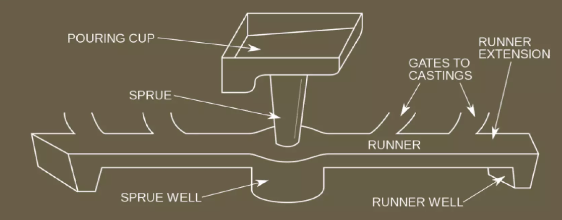
A gating system is a controlled pathway. It directs molten metal from the pouring basin into the mold cavity during casting.
The key difference between pressurized and unpressurized systems? It’s about metal flow control. Plus, where you place the choke area – the narrowest cross-section – in the runner system.
Understanding Pressurized Gating Systems
Pressurized gating systems place the choke area at the ingate design. That’s the final entry point into the mold cavity.
This setup creates a specific flow pattern. The cross-sectional area gets smaller as you move from the sprue design through the runners to the ingates.
Metal speeds up as it moves through this narrowing path. The channels stay completely filled throughout the system. This keeps molten metal under pressure right up to the cavity entrance. The result? Less turbulence in casting and minimal air entrapment.
Typical gating ratio for pressurized systems: 1:2:1 (sprue:runner:ingate) or similar ratios where the ingate area is smallest.
Understanding Unpressurized Gating Systems
Unpressurized systems take the opposite approach. The choke area sits at the sprue base. The cross-sectional area expands as metal flows from the sprue into wider runners and ingates.
This expanding shape causes the metal to slow down as it moves through the system. The runners and ingates stay partly filled during pouring. This creates an open-channel flow instead of pressurized flow.
Common gating ratio for unpressurized systems: 1:2:4 or 1:4:4 (sprue:runner:ingate), where runner and ingate areas exceed sprue area.
The Core Distinction
The classification relates to hydraulic pressure at the cavity entrance.
Pressurized systems maintain positive pressure throughout. Unpressurized systems allow atmospheric pressure in the feeding system channels.
This difference has a big impact on gating efficiency, metal velocity, and casting defects. These are critical factors in Sand casting gating applications.
Structural Design and Gating Ratio
The sprue, runner, and ingate areas have a numerical relationship. This relationship defines how your gating system performs. This gating ratio determines metal velocity, turbulence levels, and casting quality.
Calculating the Gating Ratio
The standard formula shows the relationship:
Gating ratio = As : Ar : Ag
Where:
– As = Sprue cross-sectional area (at exit/base)
– Ar = Total runner cross-sectional area
– Ag = Total ingate cross-sectional area
This ratio isn’t just theory. It controls whether your system operates as pressurized or unpressurized.
Pressurized System Ratios and Structure
Pressurized systems use ratios where the ingate area stays smallest. Common setups include:
-
1:2:1 – Used most often for ferrous castings
-
1:0.75:0.5 – Very restrictive for precise flow control
-
2:1:1 – Alternative setup for specific uses
The structural advantage? Metal stays under constant pressure. The ingate acts as the bottleneck. This forces complete channel filling upstream. Back-pressure builds throughout the runner system. Air can’t get sucked into the molten stream.
Key benefits for metal flow control:
– Less air aspiration and oxide formation
– Higher metal speeds at cavity entrance
– Smaller system volume cuts metal loss
– Better yield – less material wasted in the feeding system
These systems work best with ferrous materials and brass. These alloys have higher melting temperatures. Their flow characteristics handle the increased velocity without too much turbulence.
Unpressurized System Ratios and Structure
Unpressurized setups expand as metal flows downstream:
-
1:2:2 – Basic unpressurized layout
-
1:3:3 – Moderate expansion ratio
-
1:1:3 – Strong widening for maximum flow rate
The choke sits at the sprue base. Runners and ingates open up more. This slows metal velocity as it approaches the cavity.
Structural characteristics:
– Lower metal speeds reduce turbulence risk
– Allows greater flow rates by volume
– Open-channel flow in runners and gates
– Needs careful ingate design for complete cavity filling
The tradeoff? Larger runners and gates mean more metal trapped in the system after pouring. This cuts yield and increases material waste compared to pressurized designs.
Aluminum and magnesium castings often use unpressurized systems. These reactive metals need slower, gentler filling. This cuts oxidation and gas entrapment.
Material-Specific Gating Ratios
Different alloys need different approaches. Here’s what works in practice:
|
Material |
Recommended Gating Ratios |
System Type |
|---|---|---|
|
Aluminum |
1:2:1, 1:1.2:2, 1:2:4, 1:3:3, 1:4:4, 1:6:6 |
Mixed/Unpressurized |
|
Aluminum Bronze |
1:2.88:4.8 |
Unpressurized |
|
Brass |
1:1:1, 1:2:3, 1.6:1.3:1 |
Pressurized/Mixed |
|
Copper |
2:8:1, 3:9:1 |
Very unpressurized |
|
1.15:1.1:1, 1.25:1.13:1, 1.33:2.67:1 |
Pressurized |
|
|
Magnesium |
1:2:2, 1:4:4 |
Unpressurized |
|
Malleable Iron |
1:2:9.5, 1.5:1:2.5, 2:1:4.9 |
Mixed |
|
Steel |
1:1:7, 1:2:1, 1:2:1.5, 1:2:2, 1:3:3, 1.6:1.3:1 |
Pressurized/Mixed |
Notice the variation even within single materials. Steel shows ratios from very pressurized (1:2:1) to unpressurized (1:3:3). Your casting geometry, wall thickness, and quality needs determine the best choice.
Runner Design Principles for Flow Control
Runner geometry matters as much as ratio numbers. For unpressurized systems:
Total runner cross-sectional area must be larger than sprue exit area. The recommended ratio is 1:2 (sprue exit : runner). This expansion cuts metal velocity. The metal transitions from the vertical sprue drop into horizontal runners.
Multiple ingates feed from a single runner? The runner cross-section must decrease bit by bit along its length. Each ingate connection removes part of the flow. Cut the runner area to match. This keeps velocity and pressure even to all ingates.
Cross-section geometry optimization:
– Circular profiles work best – they cut surface area relative to volume
– This reduces heat loss during metal travel
– Lower surface area also means less friction and drag
– Streamlined shapes boost flow efficiency
Avoid sharp corners and abrupt section changes. These create turbulence spots that trap air and make oxides, no matter what your gating ratio is.
Velocity Control Through Structural Design
The 1:2 sprue-to-runner expansion ratio stops a key problem: flow separation.
Metal exits the sprue base at high speed. It then enters an oversized runner fast. The metal can separate from the channel walls. This creates voids where air gets pulled into the stream. The 1:2 ratio keeps the velocity change smooth enough to maintain wall contact. It still slows the flow.
Greater expansion ratios (1:3, 1:4) boost separation risk. Smaller ratios (1:1.5) don’t slow the metal enough. They keep too much velocity through the runner system. This defeats the purpose of an unpressurized design.
Your choices in sprue design and runner layout impact gating efficiency and defect rates in the final casting.
Flow Characteristics and Fluid Dynamics
Metal doesn’t just pour through your gating system. It follows specific fluid mechanics principles. These principles determine casting success or failure. Understanding flow characteristics separates effective designs from defective castings.
Reynolds Number and Flow Regime Identification
The Reynolds number (Re) tells you whether your metal flow control operates in laminar or turbulent conditions. This value compares inertial forces to viscous forces in the flowing metal:
Re = (ρ × v × D) / μ
Where:
– ρ = Metal density
– v = Flow velocity
– D = Characteristic dimension (hydraulic diameter)
– μ = Dynamic viscosity
Low Reynolds numbers (Re < 2000): Viscous forces dominate. Metal flows in smooth, parallel layers. This laminar flow reduces turbulence in casting and cuts down air entrapment. Most sand casting gating systems target this range.
High Reynolds numbers (Re > 4000): Inertial effects take over. Flow becomes turbulent with chaotic eddies and mixing patterns. Turbulence increases oxidation risk. It traps gases in the metal stream.
Transition zone (Re 2000-4000): Flow shifts between laminar and turbulent states. The behavior is unstable. Avoid designing systems that operate in this range.
Pressurized vs. Unpressurized Flow Behavior
Pressurized systems maintain high velocity throughout the runner system. Metal accelerates as channels narrow toward the ingate design. This creates higher Reynolds numbers—often in the transition or turbulent range. The constant pressure keeps channels filled. Back-pressure prevents air aspiration even at higher flow speeds.
The choke area at the ingate acts as a flow control valve. It forces upstream channels to stay full and pressurized. This design trades higher velocity for better mold filling consistency.
Unpressurized systems slow metal velocity through expanding cross-sections. The choke area sits at the sprue base. Wider runners and ingates reduce flow speed. This lowers Reynolds numbers into the laminar regime.
The tradeoff? Open-channel flow in runners means partial filling. Surface turbulence can occur at the air-metal interface. But the slower velocity creates gentler cavity filling. Less momentum means less turbulence.
Velocity Distribution and Flow Pattern Control
Finite volume analysis of gating systems reveals critical velocity patterns. In pressurized designs, peak velocities concentrate at the ingate entrance. That’s where metal enters the cavity. This high-speed injection can cause mold erosion and surface defects.
Unpressurized systems distribute velocity more evenly. The expanding geometry dissipates kinetic energy. Peak flow rates occur earlier in the system—at the sprue exit. Then they decrease through the runners.
Flow separation becomes critical in unpressurized designs. Metal exits a narrow sprue into an oversized runner. The stream can detach from channel walls. This creates voids where air gets sucked into the flow. The recommended 1:2 expansion ratio (sprue:runner) prevents this separation while still reducing velocity.
Computational Modeling for Gating Efficiency
Modern gating efficiency optimization uses numerical simulation. The Volume of Fluid (VOF) method tracks the metal-air interface as it moves through your system. This reveals where turbulence forms, air gets trapped, or flow stagnates.
These simulations validate your gating ratio choices before cutting patterns or making molds. They identify problem areas in sprue design and runner layout. These problems would otherwise appear after expensive trial pours.
Direct numerical simulation based on Navier-Stokes equations predicts turbulent flow behavior at specific Reynolds numbers. Results align with experimental pour tests. This gives confidence in design modifications.
The key insight? Small changes in channel geometry create dramatic shifts in flow characteristics. A 10% reduction in ingate area can push a marginal pressurized system from stable to turbulent flow. Or it can optimize an unpressurized system for perfect laminar filling.
Casting Performance and Quality Outcomes
Your choice between pressurized and unpressurized gating shapes quality in foundry operations. The gating system type affects defect formation, material yield, and production costs.
Defect Formation Patterns by System Type
Pressurized systems stop gas-related defects well. Constant positive pressure in the runner system blocks air from entering the metal stream. You get less porosity and fewer gas holes in finished castings. The choke area at the ingate design creates back-pressure. This keeps dissolved gases in solution until they escape through risers.
High velocity at cavity entry creates erosion risks, though. Metal momentum washes away mold material. This creates sand inclusions. Turbulence in casting goes up when metal hits sharp corners or sudden expansions in the cavity shape. Industry data shows pressurized systems hit defect rates below 3% for ferrous alloys with smooth transitions.
Unpressurized systems cut down on erosion defects. They fill more gently. Lower metal velocity reduces mold damage and surface turbulence. This makes them perfect for thin-walled aluminum parts where mold strength matters most. Slower metal flow control also stops cold shuts in complex shapes.
The weakness? Open-channel flow in runners creates surface turbulence where air meets metal. This makes oxide films and dross that can enter the cavity. Reactive metals like magnesium form thick oxide skins in unpressurized runners. You need careful feeding system design with filters.
Material Yield and Gating Efficiency
Pressurized gating ratios like 1:2:1 cut down on metal trapped in the system after pouring. Smaller runner volumes mean less scrap. Top foundries report scrap rate improvements of 10% after switching from unpressurized to pressurized designs for suitable alloys.
Unpressurized systems give up yield for quality. Larger runners and gates required by ratios like 1:4:4 increase metal waste. The lower defect rate makes up for this tradeoff, though. Target scrap rates below 5-10% overall. Match system type to alloy needs instead of just chasing yield.
Advantages
Each gating system type offers different benefits. You choose based on metal yield, defect control, and production costs. Know these advantages to pick the right system for your casting needs.
Pressurized System Benefits
Superior Metal Yield and Material Efficiency
Pressurized designs cut metal waste. They use compact runner geometry. The 1:2:1 gating ratio needs less total system volume than unpressurized options. Production foundries report 8-12% reduction in scrap metal after switching suitable castings to pressurized gating.
Smaller runners mean less metal hardens outside the casting. Your metal recovery rate improves. High-volume production saves you material costs over time.
Enhanced Gas Defect Control
Constant positive pressure in the runner system stops air from entering the metal stream. The choke area at the ingate design creates back-pressure. This blocks air at every junction.
Pressure maintenance cuts porosity in finished castings. Sand casting gating for steel and iron achieves defect rates below 3%. This works best with proper filters and venting.
Faster Mold Filling Speed
Higher metal velocity speeds up pouring. Thin-walled sections fill before metal starts hardening. Cold shuts and misruns don’t happen in complex shapes where metal travels long distances.
Faster filling helps ferrous castings. These often have narrow flow channels or intricate patterns that need quick cavity filling.
Unpressurized System Benefits
Reduced Turbulence and Surface Quality
Lower flow velocity cuts turbulence in casting as metal enters the cavity. Gentle filling stops mold erosion and surface flaws. Aluminum and magnesium castings get smoother surface finishes with unpressurized sprue design.
The expanding gating ratio (1:4:4 or similar) reduces kinetic energy before cavity entry. Metal arrives with less force. Delicate mold surfaces stay protected.
Better Oxide and Dross Separation
Wider runner channels let oxide films and dirt float up. The open-channel flow gives time for light contaminants to separate from the metal stream before reaching ingates.
Smart feeding system design with skimming gates catches floating dross. This natural filtering improves final casting cleanliness. No extra filter costs needed.
Flexibility for Reactive Metals
Aluminum, magnesium, and copper alloys oxidize fast at pouring temperatures. Unpressurized systems reduce oxidation. Lower surface turbulence does this. Slower metal flow control limits air contact time and oxide formation.
Industry data shows 15-20% fewer oxide-related defects in aluminum castings using unpressurized gating versus pressurized options. This quality boost makes up for the lower material yield in reactive alloy uses.
Disadvantages
No system works perfectly in every case. Each gating method has trade-offs. These affect production costs, casting quality, and how complex the operation becomes. Know these limits. They help you avoid expensive mistakes during system selection.
Pressurized System Limitations
Increased Turbulence Risk at High Velocities
Metal speeds up through narrow channels. This pushes flow into turbulent zones. The choke area at the ingate design forces high-speed injection into the mold cavity. Reynolds numbers rise above 4000 in many iron-based applications.
Turbulent flow creates oxide films in aluminum and magnesium alloys. These oxides get trapped in finished castings. Defect rates climb 12-18% when you misapply pressurized systems to reactive metals.
Sharp corners in runner system design make this worse. Turbulent eddies form at direction changes. Air gets pulled into the metal stream. This happens even with positive pressure.
Mold Erosion and Surface Defects
High metal speed damages mold walls at entry points. Sand particles wash into the casting. You get surface roughness and internal defects. Thin-walled sand casting gating sections suffer the worst erosion.
Foundries report 30-40% higher surface finishing costs on pressurized castings versus unpressurized ones for the same alloy. The aggressive filling needs stronger mold materials or protective coatings.
Complex Design and Calculation Requirements
Pressurized gating ratio calculations need exact hydraulic analysis. Small errors in sprue design dimensions change the system from optimal to defective. The metal flow control sensitivity demands experienced pattern makers. Plus, you need strict quality checks.
Temperature drops through the narrow system make pouring harder. You must superheat metal more than with unpressurized systems. This adds energy costs. Plus, it increases oxidation risk before pouring starts.
Unpressurized System Limitations
Poor Material Yield and Higher Scrap Rates
Expanding gating ratios like 1:4:4 trap significant metal in oversized runners and ingates. Production data shows 15-25% lower yield versus pressurized systems for the same casting weights.
Large feeding system volumes increase cycle times too. More metal must solidify and cool before you can remove the mold. This cuts production speed in high-volume operations.
Surface Oxidation and Dross Formation
Open-channel flow exposes the most metal surface to air. Aluminum alloys form thick oxide skins in wide runners. These films break apart. They enter the cavity as floating defects.
Magnesium castings show oxide inclusion rates 20-30% higher in unpressurized systems without effective skimming gates or ceramic filters. The gentle filling benefit vanishes once oxide contamination ruins casting strength.
Incomplete Cavity Filling in Complex Geometries
Lower flow speeds struggle to fill thin sections or intricate patterns. Metal loses temperature and fluidity during slow travel through expanded channels. Cold shuts form where metal fronts meet without proper fusion.
Long-distance horizontal flow creates specific challenges. The gating efficiency drops as metal must overcome friction across wide, shallow runners. Vertical sections may not fill all the way. This happens because metal arrives with too little momentum.
Common Applications
Foundries pick gating systems based on the metal type, part shape, and quality needs. Real factory settings show which method works best for each job.
Steel and Iron Castings with Pressurized Gating
Heavy machinery components use pressurized systems a lot. Engine blocks, transmission housings, and industrial pump bodies need tight size control. The 1:2:1 gating ratio gives steady filling patterns. Defect rates stay below 3% for ductile iron crankshafts with good pressurized ingate design.
Railway components get better metal flow control. Brake discs, wheel hubs, and coupling parts need strong build quality. Pressurized sprue design stops gas from getting trapped in key stress areas. Big rail suppliers see 10-12% material yield improvement compared to unpressurized options.
Structural steel castings for construction gear work better with pressurized systems. They boost gating efficiency. Excavator buckets, crane hooks, and lifting frames need clean internal structure. The small runner system cuts production costs. Plus, it keeps strength specs on target.
Aluminum and Magnesium Parts with Unpressurized Gating
Automotive components lead unpressurized uses. Aluminum cylinder heads, gearbox housings, and suspension parts need smooth surfaces. Gentle filling lowers turbulence in casting. This cuts oxide formation by 15-20% versus pressurized methods.
Aerospace castings need top-level cleanliness. Aircraft parts and engine pieces use unpressurized sand casting gating with Ceramic filters. The wider choke area spot lets natural dross separate out. Rejection rates for oxide bits drop a lot with the right feeding system design.
Consumer electronics housings tap into unpressurized benefits. Laptop bodies, camera cases, and smartphone frames need perfect surfaces. Slower filling stops mold wear that causes finish problems.