Picking the right foam filter feels confusing. You face many options—pore size (PPI), density, chemical resistance, and heat limits. It gets overwhelming instantly. I see projects fail often because of this. The material looks good on paper. But it fails on the job.
Are you filtering air in a sensitive HVAC system? Or skimming molten metal at 1600°C? Success means matching the foam mechanics to your environment. Use Reticulated Polyurethane for airflow. Pick rigid Ceramic for high heat. Don’t just trap particles. Balance filtration efficiency with pressure drop and durability.
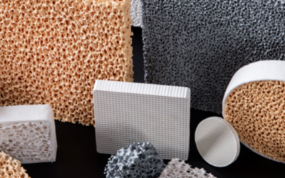
We skip the confusing terms here. We break down the main traits of common foam filter materials. You might need chemical-resistant cross-linked PE foam. Or maybe the odor control of activated carbon. We help you pick what fits your needs
Polyurethane Foam
Polyurethane (PU) foam ranks as one of the most flexible filter materials you can find today. German scientists first created this polymer back in 1937. Production grew to industrial scale in the 1950s. By the 1960s-70s, makers had built rigid closed-cell insulation foams for cold storage, LNG facilities, and HVAC systems. These foams worked well in extreme cold conditions.
Today we have reinforced polyurethane foam (RPUF). This version adds fibers and fillers to the mix. The result? Better compression strength and better performance in low temperatures.
Understanding PU Foam Structure Types
PU foam comes in two main types based on cell structure.
Flexible open-cell PU foam has connected pores throughout. Air and fluids pass through these pores easily. This makes the foam perfect for filters and cushioning. The open design bounces back after compression. Plus, it breathes well.
Rigid closed-cell PU foam works differently. It traps air in sealed pockets. This design creates strong, stiff material. Most people use it for thermal insulation, not filtration.
How do makers control the cell structure? They adjust the soft-to-hard segment mix during production. This lets them customize foam for specific filter needs. We don’t have exact porosity numbers for commercial products yet.
Density Ranges and Mechanical Properties
PU foam density changes a lot based on what you need it for. Lightweight filter-grade foams range from 16 to 130 kg/m³.
Here’s a real example: Lab samples sized 50×50×50 mm weigh 12.63g and 15.88g. These give densities of 110 kg/m³ and 130 kg/m³. Commercial rigid closed-cell cores sit around 96 kg/m³ (6 pcf).
Density affects how the foam performs. A 62 kg/m³ foam has compressive strength of 0.64 MPa parallel to foaming direction. Lower-density 16 kg/m³ material? Just 0.033 MPa.
Shear strength for 62 kg/m³ foam runs from 0.34 to 0.36 MPa. The exact number depends on which direction you measure.
Fatigue testing shows something important: stress above 0.25 MPa cuts down durability fast. This matters a lot for high-pressure filter systems.
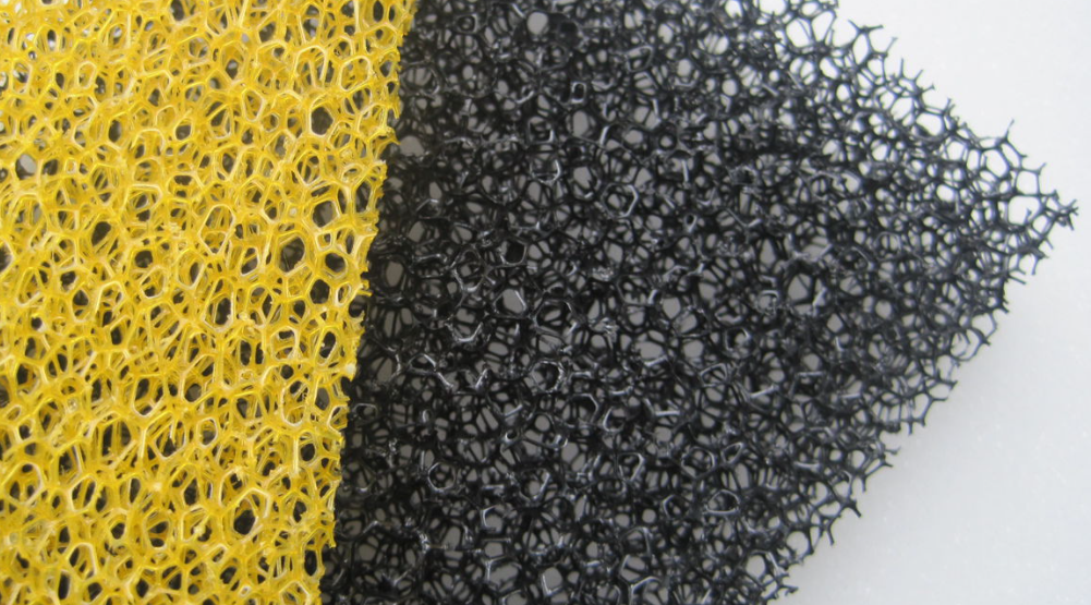
Reticulated Foam (Reticulated Polyurethane)
Making reticulated foam takes two steps. This process turns regular polyurethane into a top-grade filter material. Makers start with standard open-cell polyurethane foam. This can be polyether or polyester-based. The key step is “reticulation.” This removes the cell membranes. You’re left with a 3D skeletal structure.
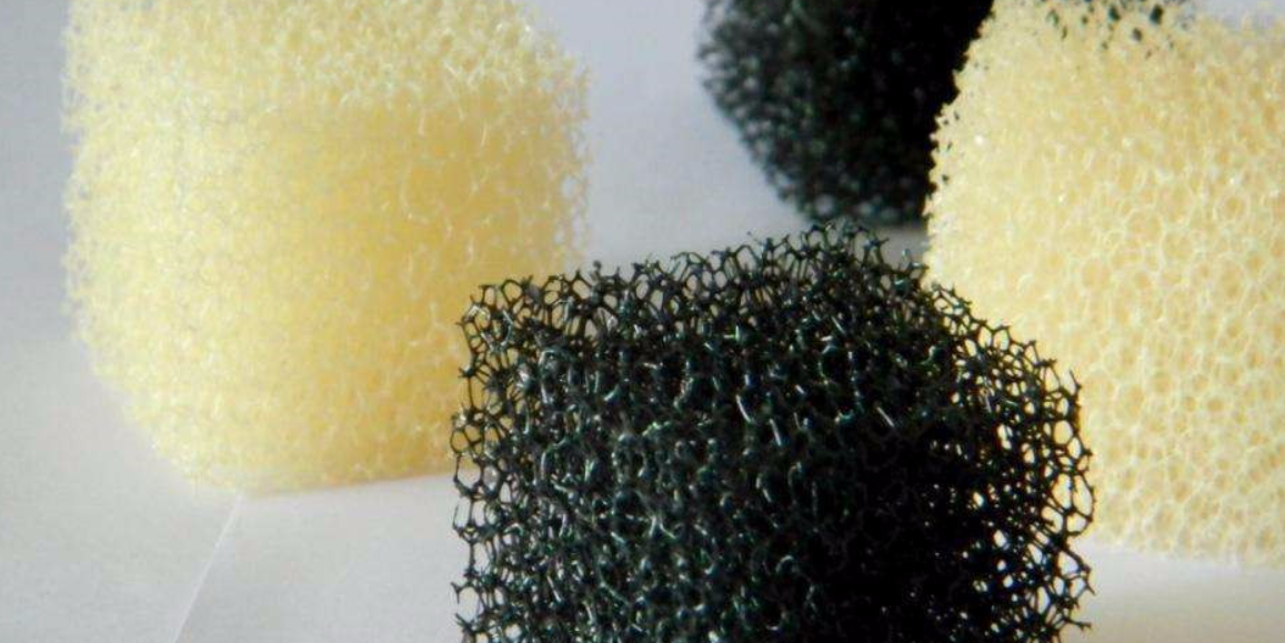
How Manufacturers Create the Reticulated Structure
Two methods handle most reticulation work:
Thermal explosion method burns off the thin membranes. Makers put the foam in a sealed chamber. The chamber holds combustible gas and air. They ignite it. The fast burn vaporizes the cell windows. The structural skeleton stays intact. This builds the open-web design.
Chemical dissolution method uses alkaline solutions or special chemicals. These dissolve the pore membranes. The foam skeleton stays whole. The connecting films break down
Polyethylene Foam
Polyethylene (PE) foam started in packaging. Makers used it for shipping protection and flotation devices. Engineers later found its closed-cell structure, low water absorption, and chemical resistance worked great for filtration. You’ll find it in liquid pre-filters, gas filters, and support layers across many industries.
Cross-linked polyethylene foam (XLPE) changed everything. Cross-linking builds stronger molecular bonds. You get better mechanical strength, better resistance to swelling, and more precise pore structures. HVAC systems use XLPE for pre-filtration. Car makers put it in air intake filters. Chemical processors depend on it for liquid pre-filter carriers.
Density Ranges and Available Specifications
PE foam offers a wide density range for different filtration needs.
Standard closed-cell PE foam densities include:
– 18, 24, 33, 45 kg/m³ (about 1.1–2.8 pcf)
– 1.2, 1.7, 2.2, 4.0, 6.0, 9.0 pcf (19, 27, 35, 64, 96, 144 kg/m³)
– ARPLANK EPE products range 1.3–4.6 pcf (20–74 g/L)
Cross-linked PE foam (XLPE) comes at:
– 4 pcf (64 kg/m³)
– 6 pcf (96 kg/m³)
Suppliers let you customize density, thickness, pore size, and hardness. Common thicknesses run from 1/32″ and 1/16″ up to several dozen millimeters.
Pore Structure and Mechanical Performance
Cell size in closed-cell PE foam measures 0.3–0.4 mm. The exact size shifts with density. Lower density gives 0.3 mm cells. Higher density pushes toward 0.4 mm.
Cell count ranges from 18 to 30 cells per inch as density climbs from 1.2 to 9.0 pcf. Manufacturers adjust pore diameter in the 0.2–0.5 mm range by changing foaming ratios and cross-linking methods. PE foam works great for coarse filtration, pre-filtration, or support layers in multi-stage filter systems.
Physical properties change with density (PE foam sheet data):
Density 18 kg/m³:
– Hardness: Shore OO 50
– Tensile strength: 300 kPa
– Elongation at break: 125%
– Tear strength: 520 N/m
Density 45 kg/m³:
– Hardness: Shore OO 60
– Tensile strength: 560 kPa
– Elongation at break: 175%
– Tear strength: 1,150 N/m
Cross-linked PE foam (4 pcf) shows:
– Tensile strength: 70–130 psi
– Elongation at break: 180–200%
– Compression set (158°F, 24h): <0.6%
Water absorption stays very low. One-day immersion tests show just 0.02–0.06 lb/ft² uptake across the 1.2–9.0 pcf density range. Long-term compression creep runs about 0.8–6% under 25% compression. PE foam keeps stable filtration performance in wet or pressurized conditions.
Activated Carbon Foam
Activated carbon foam mixes the structure of reticulated polyurethane with the absorption power of activated carbon. You get a filter material that traps both particles and VOCs (volatile organic compounds). Carbon content is what counts most. Commercial products pack ≥45–50 wt% activated carbon into the foam. Some makers set carbon content >45% as their minimum. The carbon comes from coconut shell or coal-based activated carbon powder and granules.
Structural Specifications and Available Formats
The base uses polyurethane reticulated foam. This open-web design lets air flow through. At the same time, it maximizes contact with carbon particles. Porosity ranges from 10–60 PPI (pores per inch) for granular activated carbon foam products.
Thickness options run 3–25 mm for standard use. Specialized products stretch this to 3–100 mm for heavy-duty filtration. Standard sheet sizes reach up to 100×200 cm or 120×200 cm. Maximum dimensions hit 2 m length and 1 m width. Pick between flame-retardant or non-flame-retardant versions based on your safety needs.
Surface Area and Pore Structure Performance
Adding activated carbon changes the foam’s surface features. Research using polyurethane foam with 0–20% activated carbon by weight shows clear patterns.
Specific surface area (BET) climbs with carbon loading:
– Plain foam (0% AC): baseline reference
– AC5 (5% AC): micropore surface area 18.67 m²/g; cumulative pore volume 0.078 cm³/g (2.8× plain foam)
– AC10 (10% AC): total specific surface area 62.75 m²/g
– AC15 (15% AC): 106.48 m²/g total specific surface area (maximum in study)
– AC20 (20% AC): 83.91 m²/g (drops due to poor spread at high loading)
Micropore performance peaks at 15% loading:
– AC5: micropore volume 7.40 cm³/g (7× plain foam)
– AC10: micropore surface area 29.01 m²/g
– AC15: micropore volume 29.80 cm³/g; micropore surface area 69.16 m²/g (highest values)
– AC20: micropore surface area 49.00 m²/g
Average pore size drops with carbon content:
– Plain foam: 9.99 nm
– AC10: 7.17 nm
– AC15: 4.87 nm
– AC20: 5.58 nm
The data shows a clear trend. Adding activated carbon up to 15% gives you 4–10× increase in specific surface area and 7× increase in micropore volume. Average pore size drops. These smaller pores trap gas molecules better.
Real-World Absorption Performance
Commercial granular activated carbon reticulated foam gives strong VOC removal:
– Benzene removal: >90%
– Iodine number: >1000 mg/g
– Effective removal of ethanethiol and similar compounds
Another activated carbon foam product lists benzene absorption >22% by weight. High carbon content plus large surface area make these foams effective against benzene and other VOCs. This performance level fits industrial air cleaning, odor control systems, and chemical vapor filtration uses.
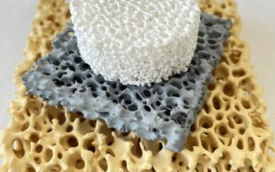
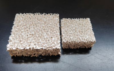
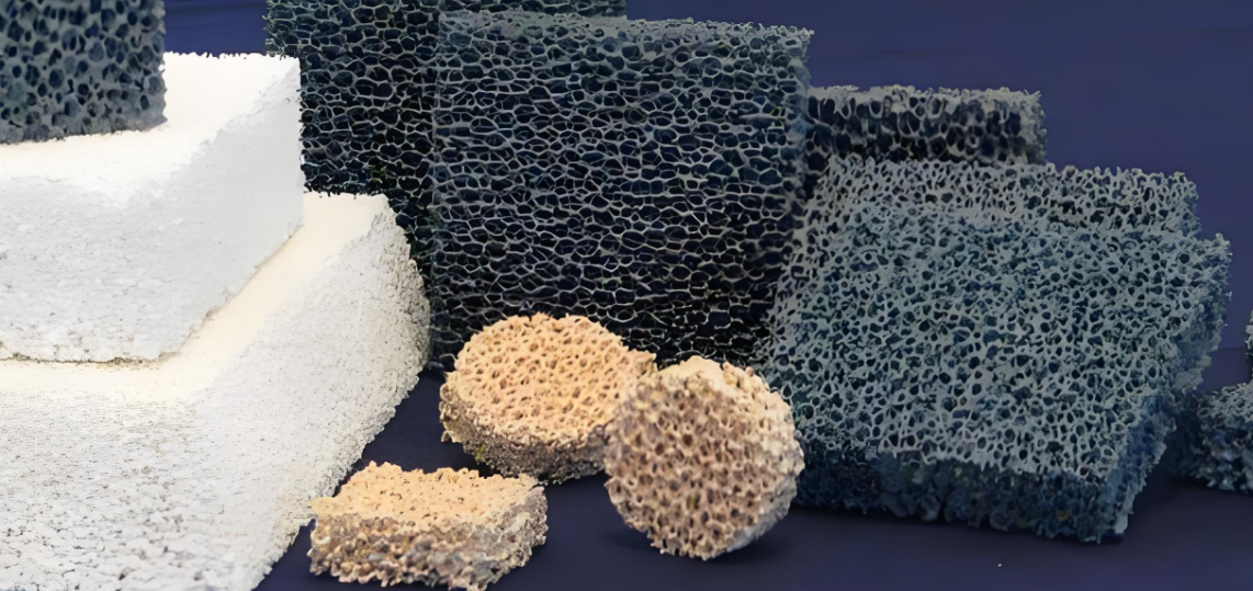
Ceramic Foam
Ceramic foam appeared as a filtration solution in the 1970s and 1980s. Engineers created the polymer sponge replication method back then. This technique became the go-to process for making ceramic foam filters in metal casting. Modern ceramic foams use different base materials: Al₂O₃ (alumina), SiC (silicon carbide), ZrO₂ (zirconia), and cordierite. Pick the right one for your application. These materials handle high temperatures and stay chemically stable. Metal and plastic foams can’t do that.
The key feature? 80–95% open porosity. Pores connect throughout the entire structure. This creates the high porosity. Your manufacturing recipe and process control determine the exact porosity level.
How to Make Filter-Grade Ceramic Foam
Polymer sponge replication (PU template method) leads ceramic foam filter production.
Start with ceramic powders: Al₂O₃, SiC, ZrO₂, or cordierite. Mix them with deionized water and dispersant in a ball mill. Add binder and plasticizer. Stop when you get “thick cream” thickness.
Dip a polyurethane foam template into this slurry. Cover it all. Squeeze it several times to push out extra slurry. This keeps the pores open and linked.
Dry the coated foam at low temperature. Go slow. This stops cracking. Next, remove organics: heat at 1–2 ℃/min through the 200–500 ℃ range. Hold at 600 ℃ to break down the PU and all organic binders.
Final sintering uses different temperatures for different materials. Al₂O₃ needs ≈1600 ℃. Cordierite fires at ≈1200 ℃. Cool it down in a controlled way. This prevents thermal shock damage.
Direct foaming gives you a simpler path. Mix ceramic slurry with foaming agents (protein or synthetic surfactants). Stir it hard or inject gas to create bubbles. Add stabilizers for the foam structure. Then dry and sinter.
You control porosity and pore size without a template. That’s the benefit here.
Starch consolidation uses food-grade starch as a pore maker. Mix it with ceramic powder and water. Pour, solidify, and dry. Burn out the starch at 300–600 ℃. Then sinter at high temperature to build the foam structure.
Gelcasting foams offer tight control. Add monomers and crosslinkers to the slurry. Create foam through mechanical or chemical methods. The gel solidifies. This locks the bubble structure in place. Dry and sinter to finish. You get exact control over pore size, porosity, and density.
Other methods work for special shapes and sizes. These include emulsion techniques, pressing, extrusion, and slip casting.
High-Temperature Performance
Al₂O₃ ceramic foam filters sinter at 1600 ℃. They handle molten steel at 900–1200 ℃ in aluminum casting. Long-term working temperature stays below 1600 ℃. This fits the limits of alumina-based ceramics in constant high-heat settings.
Metal Foam
Metal foam gives you clear structural benefits for filtration. Engineers bond aluminum, nickel, stainless steel, copper, titanium, or tantalum into open-cell networks. You get metal-level heat transfer, mechanical strength, and corrosion resistance plus 70–95% porosity. This combination works best in high-temperature gas filtration, catalyst supports, and corrosive liquid pre-treatment systems.
Common Metal Foam Materials and Key Specifications
Aluminum foam (Al foam) is the lightest choice. Density ranges 0.2–0.8 g/cm³—just 7–30% of solid aluminum. Porosity hits 70–95% in open-cell versions. Heat transfer stays at metal levels but drops in direct proportion as relative density decreases. Aluminum fights corrosion well in ambient air and neutral water.
Nickel foam (Ni foam) leads in electrode and catalyst carrier uses. Porosity reaches ≥90%. Pore size runs from tens to hundreds of microns. This works for fine particle filtration and electrochemical systems. Nickel-based materials beat carbon steel in alkali and neutral environments. Strong acid or strong oxidizing conditions? You’ll need Ni-Cr alloys instead.
Stainless steel foam (304/316L grades) handles the toughest conditions. Porosity sits at 80–95% with custom options available. Long-term working temperature reaches 600–800 °C based on steel grade and load. 316L foam beats 304 in chloride-containing media and weak acids. Chemical processors use it for filtration and catalyst supports.
Copper foam (Cu foam) delivers high electrical transfer, heat transfer, and electromagnetic shielding. Research shows 85% porosity copper foam achieves >90% energy absorption efficiency. Engineers use it in pressure relief buffer systems.
Titanium and tantalum foams serve specialized roles. Pick these for extreme high-temperature, strong corrosion, or biocompatibility needs in chemical processing and medical implants.
Mechanical Strength and Pressure Resistance
Strength depends on relative density, pore size, open-to-closed cell ratio, and alloy grade. These ranges guide initial material selection.
Aluminum foam (relative density 0.1–0.3) shows compressive yield strength from 2–10 MPa at low density. High density reaches 10–30 MPa. The stable yield plateau enables volume energy absorption around 10–30 MJ/m³. This makes aluminum foam effective for impact energy absorption components.
Nickel foam at high porosity (≥90%) delivers static compressive strength in the low MPa range. Higher-density products reach about 10–20 MPa. Tensile strength falls far below solid nickel. Use nickel foam as a support skeleton, not primary load-bearing structure.
Stainless steel foam (304/316L, porosity ~80–90%) provides compressive yield strength in the 10–40 MPa range. Strength rises fast with increasing relative density. High-temperature compression strength at 600 °C drops but still beats aluminum foam at the same density.
Copper foam (porosity ~85%) targets energy management applications. Specific strength values vary with manufacturing method and final density specification.
Electrostatic Foam Media
Static electricity boosts foam filter performance. This foam type pairs the open-cell structure of standard filter foam with electrical properties. The foam holds a static charge. That charge attracts airborne particles to the foam strands. You catch more dust, pollen, and tiny particles. Pressure drop stays the same. Air purifiers use this technology. So do HVAC pre-filters and electronics clean rooms. It beats mechanical trapping alone.
Electrical Properties That Enable Static Filtration
Electrical resistance range shows how well foam holds and manages static charge.
Conductive-grade PE foam keeps surface resistivity between 10³–10⁶ Ω/sq (CE series products). This level lets charge dissipate in a controlled way. It stops dangerous voltage buildup.
Static-dissipative PE foam runs at 10⁶–10⁹ Ω/sq (DE series). Higher resistance means electrostatic fields stay active longer. The foam holds charge. It doesn’t release too fast.
Black conductive foam shows 10²–10⁵ or 10³–10⁵ Ω/sq depending on grade. Pink anti-static closed-cell PE foam stays below 10¹² Ω surface resistance.
Volume resistivity for conductive PE foam ranges 10³–10⁶ Ω·cm. These numbers match the surface resistivity levels above.
Density sits at 40–60 kg/m³ for most conductive and static-dissipative PE foams. Ethafoam anti-static versions run about 29 kg/m³ (1.8 pcf). Conductive packaging foam weighs 1.7–1.99 lb/ft³.
Mechanical properties support multi-stage filter assembly:
– Tensile strength: 31 psi (≈215 kPa)
– Elongation at break: 50%
– Tear strength: 10 lb/in (≈1.75 N/mm)
How Manufacturers Build Static-Holding Foam Structures
Makers blend PE resin + conductive filler (carbon black) + foaming agent. They extrude this mix. Then they use radiation to cross-link the polymer chains. After that, they foam the material. The result? Closed-cell foam with internal conductive pathways running through it.
Surface resistivity control in the 10³–10⁹ Ω/sq range creates balance. The foam holds electrostatic charge and field without releasing it too fast. At the same time, it stops hazardous voltage buildup through slow, controlled release.
Internal anti-static technology beats surface treatments. Products like ETHAFOAM Select Anti-Static use “internal anti-static” formulas. The anti-static properties last longer. Surface wear and cleaning don’t hurt the charge-holding ability. Surface-coating methods fade faster with use and washing.
For air filtration, manufacturers design foam with pore density between 10–80 PPI (Pores Per Inch). This range balances airflow resistance against particle contact chances. The electrostatic charge extends the capture zone around each foam strand. Particles smaller than the pore openings still get pulled in. Electrical attraction traps them.