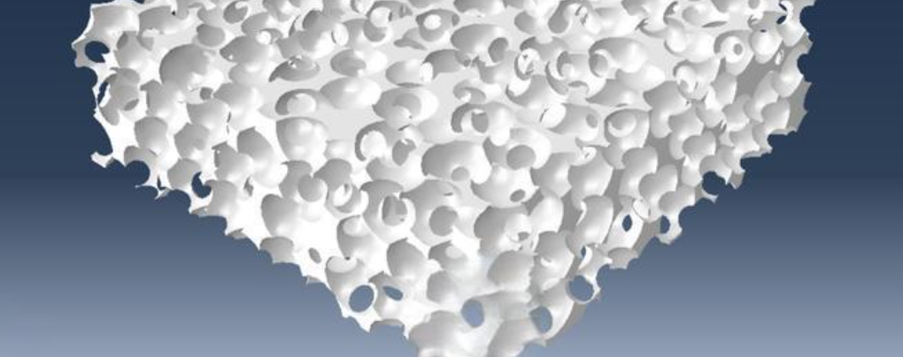
Metal foam is a game-changing material. It looks like frozen bubbles trapped in solid metal. This material has changed industries—from aerospace to medical devices.
The foam weighs very little and looks like a sponge. But it packs a powerful mix of features. It absorbs energy exceptionally well. Heat moves through it faster than through many materials. Plus, its strength-to-weight ratio beats most traditional metals.
Understanding the properties and characteristics of metal foam matters for engineers, designers, and innovators. You need cutting-edge solutions for tough technical problems. This material delivers.
You might work on thermal management for electronics. Or maybe you design impact-resistant structures. Perhaps you develop acoustic damping systems. The cellular structure of metal foam gives you capabilities solid metals can’t offer.
Metal Foam Definition and Basic Structure
Metal foam has a solid metal frame—usually aluminum—filled with gas pockets. These pockets take up 75-95% of the total volume. The base metal uses just 5-25% of the space. This creates a density that’s 5-25% of the original solid alloy. Picture a metallic sponge where air fills most of the structure.
Porosity affects performance. Standard metal foams maintain 75-95% void spaces. A foam with 20% solid content delivers over twice the strength of a 10% dense version. More metal means greater load capacity. The relationship follows a power-law pattern.
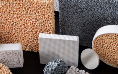
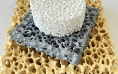
Two Fundamental Structure Types
Closed-cell structures have isolated, sealed pores. Each bubble stays separate from its neighbors. This design floats in water. It resists fire. Recycling is easy. The material keeps its deformed shape after impact—it won’t spring back. Engineers attach closed-cell foam to aluminum plates. This creates sandwich panels that add stiffness. Under compression, these foams hold a constant stress level until 80% crushing occurs.
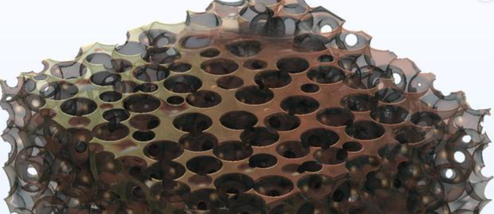
Open-cell structures have connected pores. The pores form a continuous network through the material. The surface area reaches 250-10,000 m²/m³—much higher than solid metal. This connection allows fluid flow. Open-cell foam works well for heat and mass transfer tasks. Researchers use it as a support base for phase-change materials (PCMs), metal-organic frameworks (MOFs), and zeolites. Fluid exchange is key in these uses.
Pore Architecture and Dimensions
Cell sizes reach up to 7-10 mm in diameter. The large pores look spherical and connected. They match the size of space-holder materials like potassium carbonate used during making. Beyond these large voids, tiny pores exist within the struts and cell walls. Engineers can adjust both the ligament thickness and pore spread.
Syntactic foam variants use hollow spheres—micro-glass, metallic, or ceramic—in the structure. These spheres create finer, more exact pores compared to standard foaming methods.
Base Metal Selection
Different metals offer unique benefits for foam uses:
|
Metal |
Key Characteristics |
|---|---|
|
Aluminum & Al alloys |
Weighs just 10-25% of solid aluminum density; won’t catch fire; great at thermal insulation, sound dampening, vibration absorption, and impact protection; most common choice because the melt foaming process is easy. |
|
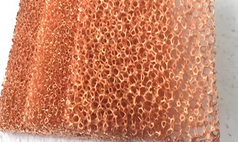
Copper |
Shows strong growth potential; creates large and tiny pores through powder metallurgy; keeps excellent thermal and electrical flow. |
|
Nickel, Magnesium, Zinc, Stainless Steel |
Handles high stress under compression; needs specific stabilization techniques during production for each alloy type. |
Composite Metal Foam (CMF) Architecture
CMF is an advanced type that uses hollow metal spheres set in a metallic matrix. The structure contains 70% air. This makes it 70% lighter than solid metal. These closed-cell designs achieve a 5-6x better strength-to-density ratio than earlier foam materials. Energy absorption jumps 7 times higher compared to standard metal foams. The spheres arrange in cubic or body-centered cubic patterns. This gives optimal load spread.
Mechanical Properties and Performance
Can metal foam handle real-world use? Load-bearing capacity answers that question. The mechanical behavior breaks down into two parts: strength values you can measure and how the material deforms under stress.
Strength Parameters Across Loading Conditions
Compression strength is the main test for metal foam. The cellular structure handles crushing forces better than pulling or twisting. High-performance aluminum foams hit compressive strength between 2-10 MPa at relative densities of 0.05-0.20. Denser variants reach 20-40 MPa as solid content increases to 25-30% of total volume.
Tensile strength runs lower than compression. It measures 40-60% of compressive values for the same density. Open-cell aluminum foams show tensile strength around 0.8-4 MPa. This depends on strut thickness and cell connectivity. The connected pore network creates weak points. Cracks spread faster here under pulling forces.
Shear strength falls between tensile and compressive performance. Testing follows ASTM C273 standards for sandwich core materials. Aluminum foam cores deliver shear strength of 1.5-6 MPa at densities that match structural panel needs. The value rises with density. It follows power-law relationships.
Three-Stage Deformation Behavior
Compress metal foam and you get a distinct stress-strain curve with three clear zones:
Stage 1: Linear Elastic Region occurs at strain below 5%. The cell walls bend but spring back. Young’s modulus ranges from 0.1-3 GPa for aluminum foams. This depends on relative density. Remove the load here and the material returns to its original shape. No permanent damage occurs.
Stage 2: Plateau Region runs from 5% to 60-70% strain. Cell walls buckle and collapse through the material, layer by layer. Stress stays constant. This creates an ideal energy absorption zone. The plateau stress measures 1-8 MPa for aluminum foams. Collapse happens in crush bands that spread through the structure. No elastic rebound occurs during this phase.
Stage 3: Densification starts at strain above 60-80%. Collapsed cell walls touch and pack together. Stress rises fast as the material acts like solid metal. The densification strain point varies with initial porosity. Higher void content delays this stage.
Energy Absorption Metrics
The plateau region gives you exceptional impact protection. Specific energy absorption (energy per unit mass) reaches 15-30 kJ/kg for aluminum foams at 50% compression. Composite metal foams (CMF) absorb 7 times more energy than standard types. Values exceed 100 kJ/kg before densification. This performance beats polymer fooms and matches advanced honeycomb structures.
The constant plateau stress means energy disappears without damaging force spikes. This works great for crash protection, blast mitigation, and shock isolation. Controlled deformation matters more than rigidity in these cases.
Thermal Management Characteristics
Metal foam moves heat away from critical components well. Aluminum-based foams have thermal conductivity from 5-30 W/(m·K). This depends on porosity and base alloy mix. The range sits between traditional insulation and solid metals. The cell structure creates many heat transfer paths. Heat moves through both the metal parts and the air-filled spaces.
Heat Dissipation Performance
Open-cell metal foams beat flat surfaces at moving heat. The connected pore network gives more contact area with cooling fluids. Air flowing through aluminum foam shows heat transfer rates 3-5 times higher than smooth metal plates at the same flow speeds. The winding path creates turbulent mixing. This breaks up thermal boundary layers that usually block heat exchange.
Two-phase cooling systems with metal foam cores show 9.11% CAGR growth through 2030. These systems include vapor chambers, heat pipes, and immersion setups. They beat traditional air cooling in high heat-flux uses. Data centers drive this shift. Their energy needs will double by 2026. Current power usage effectiveness (PUE) stays at 1.58. So operators turn to liquid cooling solutions. Metal foam works as structured wicking material in these setups.
Thermal Resistance and Interface Performance
Thermal resistance measurements change a lot with foam density and cell shape. Slot-liner to slot-winding interfaces in electric motors show starting resistance values near 1,800 mm²-K/W. Sample-to-sample differences reach ±60% in heat sink uses. This happens because of manufacturing gaps in pore structure. Engineers must factor in this spread using confidence ranges during thermal system design.
The thermal management hardware segment holds 58.62% revenue share in the cooling market. The market value hits USD 13.67 billion in 2025. Metal foam parts add to this through heat sinks, cold plates, and thermal interface materials. North America takes 33.3% global market share. Data center infrastructure leads this. These facilities need advanced thermal solutions that use metal foam’s unique heat transfer properties.
Fluid Flow and Permeability Properties
Permeability shows how well fluids pass through metal foam’s connected pore network. This property varies widely—up to 13 orders of magnitude across different porous materials. Cell structure, porosity levels, and pore connections cause these differences.
Understanding Permeability in Metal Foam Structures
The Kozeny-Carman relation predicts permeability using several structural inputs. You need data on porosity, specific surface area, tortuosity (how twisted the flow paths are), characteristic length, pore size, constriction factor, fractal dimension, and more. These factors build a detailed picture of flow resistance.
Darcy’s law governs fluid flow through metal foam: q = -k/μ * ∇p. Here q represents flow velocity (m/s), k is permeability (m²), μ is fluid viscosity, and ∇p is the pressure gradient. Higher permeability means easier flow at the same pressure difference.
Open-cell aluminum foams with 85-95% porosity show permeability values from 10⁻⁸ to 10⁻¹⁰ m². This range works well for heat exchange, filtration, and catalytic uses. The connected pore structure creates continuous flow channels. Solid metals can’t offer this.
Electrical and Acoustic Properties
Metal foam’s cellular structure affects electrical conductivity and sound absorption differently than solid metals. The void spaces and metal struts create unique paths for electrons and sound waves.
Electrical Conductivity Characteristics
Open-cell foam has connected metal struts that conduct electricity. But porosity reduces overall conductivity compared to bulk metal. Current flows through the twisted network of struts rather than straight paths. This increases electrical resistance based on the void fraction. Closed-cell types show even lower conductivity. Isolated bubbles interrupt electron flow entirely.
Some applications need both electrical function and lightweight design. This balance works well for them. EMI shielding uses metal foam where moderate conductivity is enough. Battery electrodes use foam structures to maximize surface area. They still maintain electron transport. The trade-off between weight savings and conductivity loss is important in these electrical systems.
Acoustic Absorption Performance
Sound waves enter metal foam’s pore network and lose energy through several ways. Air friction within narrow channels turns acoustic energy into heat. The metal struts vibrate and absorb sound through structural damping. Multiple reflections within the cellular maze scatter sound waves well.
The frequency response spans broad bands, narrow bands, and discrete tones. Engineers measure absorption using 1/1 or 1/3 octave bands with A-weighting. Background noise stays at least 3 dB below the source level during testing. Temperature control maintains 15-30°C with constant humidity. This ensures repeatable results.
Chemical Stability and Environmental Resistance
Metal foam holds up well in tough conditions that break down many standard materials. The base metal decides how the foam reacts to its surroundings. Aluminum-based foams—the most common type—resist corrosion well in pH 4.5-8.5 ranges. These ranges are typical in factories and mild chemical settings.
Corrosion Resistance Performance
Aluminum forms a protective oxide layer (Al₂O₃) on exposed surfaces. This film protects the metal underneath from more oxidation. Metal foam has a large surface area—250-10,000 m²/m³ in open-cell types. More surface needs protection. But the oxide layer forms evenly across all strut surfaces and cell walls.
Long-term stability tests in controlled settings prove the foam lasts. Samples stored at 5°C for 24 months across three production batches show little wear. Conditions at 25°C/60% RH keep the structure and chemistry stable for 6-12 months. The oxide layer stays intact. These results match pharmaceutical-grade stability standards. The material stays consistent over long use.
Temperature Stability and Fire Resistance
Aluminum foam types like Duocel® melt near 1,220°F (660°C). This heat level is higher than typical fire temps in cars and buildings. The material won’t catch fire or burn. That’s a key safety edge over polymer foams. The cell structure insulates heat even as the base metal gets soft.
High-heat uses gain from this stability. Engine parts handle constant heat cycles without breaking down. Thermal systems work well because the metal keeps its oxide shield during heating and cooling cycles.
Metal Foam Types and Their Specific Properties
Different manufacturing methods create distinct metal foam types. Each type works best for specific engineering tasks. The structure of each foam type sets its performance limits and best uses.
Open-Cell Metal Foams: Maximum Flow and Exchange
Open-cell structures have interconnected pore networks throughout the material. The pores connect at two levels: macro-level spherical voids (matching space-holder materials like potassium carbonate K₂CO₃) and micro-level channels in the struts and cell walls. This two-scale pore system gives you great fluid access.
Porosity ranges from 70-91% void space. Aluminum foams hit 91% porosity using calcium chloride (CaCl₂) dissolution. The exchange surface area reaches 250-10,000 m²/m³—much higher than solid metal plates. Thermal conductivity stays at 5-30 W/(m·K). This balances light weight with heat transfer.
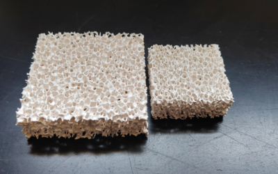
Closed-Cell Metal Foams: Sealed Protection
Closed-cell designs trap separate gas bubbles in metal walls. Each cell stays isolated from neighbors. Cell sizes stay uniform, forming equiaxed polyhedral or spherical shapes. A359 aluminum with Al₂O₃ particles shows spherical cells below 70% porosity. Above that level, cells shift to polyhedral shapes. Magnesium foams show polyhedral cells at 87% porosity.
The sealed design gives ~70% air content by volume. This makes the foam 70% lighter than solid metal. You get waterproof features too. The closed structure blocks water entry. Isolated cells handle moisture, thermal shocks, high pressures, and extreme temperatures without internal damage.
Density stays at 5-25% of bulk solid metal. Shock absorption and sound dampening remain strong. Trapped gas cushions impacts. Each cell compresses on its own without fluid escape. This creates steady energy absorption through the stress-strain curve.
Composite Metal Foams (CMF): Advanced Strength
CMF tech puts hollow metal spheres in a solid metal matrix. This creates ~70% air content through careful design. Steel-steel CMF gets 5-6 times better strength-to-density ratios than standard metal foams. Energy absorption jumps more than 7 times higher than older foam types.
Greater strength stops blasts and fragment impacts. Tests show no bowing or cracking under explosive loads. A 16.7 mm thick CMF panel stops incendiary fragments cold. The material catches fragments at the impact site. Failure doesn’t spread through the structure.
CMF beats all other foam types for heat blocking. CMF holds back 1,100°C (2,000°F) heat within a few inches of material. Room temperature sits just 2 inches away from the hot surface. Steel-based CMF keeps its strength at these high temps. Aluminum versions would melt. Low heat transfer shields sensitive parts behind the barrier.
Mesh-Type Metal Foams: Tailored Architectures
Mesh-type foams like Duocel® aluminum and copper use woven wire mesh or sphere-and-wire templates for rigid structures. Titanium foams reach 1,668 µm pore sizes. Steel foams measure 1,371-1,540 µm through leaching or electrochemical breakdown of space-holder materials.
Open pores and high connectivity let engineers control pore size and shape with accuracy. Sodium chloride (NaCl) particles copy their shape in the final structure after leaching. This matters for filters and catalyst systems that need specific flow resistance.
Compaction pressure changes cell geometry. 300 MPa compaction makes dense cell walls with spherical pores. Push to 400 MPa and cells deform into ellipsoidal shapes. Mechanical and flow properties change in known ways.
Comparative Performance Across Metal Types
|
Foam Type/Metal |
Porosity/Density |
Strength/Energy Absorption |
Thermal Performance |
|---|---|---|---|
|
Aluminum foams |
70-91% porosity; variable relative density |
High compressive strength and stiffness; secondary cell formation boosts strength |
5-30 W/(m·K) effective conductivity |
|
Magnesium foams |
87% porosity with polyhedral cells |
High energy absorption capacity |
Excellent shock resistance |
|
Copper foams |
Macro/micro-pore combinations; high connectivity |
Moderate strength |
Superior thermal conductivity |
|
CMF (steel-steel) |
70% air content (30% solid) |
5-6x strength-to-density ratio; >7x energy absorption |
Isolates 1,100°C within inches |
PPI (pores per inch) and relative density control the main physical and mechanical properties. Local porosity varies by 1% at 29% overall porosity, 2% at 39%, and 3% at 49% in magnesium-carbon nanotube blends. Hybrid designs with thin film coatings boost strength and fight corrosion better than base metal alone.
FoundryMax Filtration Solutions: Specialized Foam for Metal Casting
Let’s talk about casting in the real world. Impurities in molten metal are a nightmare for foundries. You spend hours prepping the mold and melt. Then inclusions ruin the final part. FoundryMax fixes this issue.
We produce high-performance foam filters for metal filtration. Generic foam materials often fail. Our filters withstand extreme thermal shock and erosive molten flow. Pouring aluminum, iron, or steel? These filters trap slag and dross. They also smooth out turbulence.
See this as quality insurance. Choose FoundryMax’s foam filters. You get lower scrap rates. You also produce cleaner, stronger metal parts. Care about casting quality? Get a filtration solution that works as hard as you do.
Production Methods Impact on Properties
How you make metal foam changes its internal structure and performance. The same base metal gives you very different results based on your process.
Process-Induced Structural Variations
Compression molding (CM) versus injection molding (IM) creates big differences in P(L/DL)LA/PLCL blend foams. CM samples show 20% lower modulus of elasticity, stress, and strain at yield compared to IM. The deformation gap gets even wider. CM achieves 3 times higher deformation at break. But CM comes with high variability. IM shows coefficient of variation reaching 75% for this metric.
Chain orientation explains these differences. IM creates higher crystallinity. Crystallization temperature (Tc) peaks near 90°C. The polymer chains align during injection flow. This boosts yield stress and tensile modulus. CM produces no Tc peak. The chains arrange randomly. This reduces crystallinity levels. The result? Strain-hardening behavior after yield point. IM gives you strain-softening response instead. Both methods maintain glass transition (Tg) around 60°C and melting point (Tm) near 160°C.
Manufacturing Quality Control Effects
Metal fabrication errors trace back to poor material selection 51% of the time. Engineers ignore how different processes change mechanical properties. Component failures happen in real-world use because of this.
Surface treatments alter roughness, hardness, wear resistance, and porosity. Electroplating or vacuum deposition reduces air bubbles and surface defects. Heat treatments boost tensile strength, ductility, and corrosion resistance at the same time. Coating thickness and uniformity control how well the foam resists chemical attack. They also control heat and electricity flow.
Additive manufacturing (AM) gives you better mechanical properties than traditional foaming methods. Wet abrasive finishing improves surface quality on AM parts. Build orientation during 3D printing affects tensile properties. It also affects dimensional accuracy and surface finish. Optimize your print direction for your specific performance targets.
Conclusion
Metal foam blends innovation with real-world use. You get lightweight construction paired with strong performance across multiple functions. These materials excel at heat control, noise reduction, energy absorption, and chemical resistance. Aerospace, automotive, medical, and industrial sectors all rely on them.
Metal foam properties depend on three key factors: the base metal you choose, how the cellular structure is designed, and which manufacturing method you use. Need open-cell structures for heat exchange? Or closed-cell types for structural support? Knowing these basic properties helps you pick the right material for your engineering needs.