Metal casting defects cost manufacturers millions each year. Porous surfaces appear. Gas bubbles get trapped. Non-metallic bits sneak in. These problems weaken the metal structure and lead to costly fixes.
Silicon carbide (SiC) ceramic foam filters work as a key quality control tool. They act like 3D strainers. Contaminants get caught while molten metal flows through connected pores.
Many foundries face challenges though. Picking the right pore size is tricky. Filter placement matters too. Plus, it’s hard to know if the cost beats cheaper options.
What Are SiC Ceramic Foam Filters? (Definition and Structure)
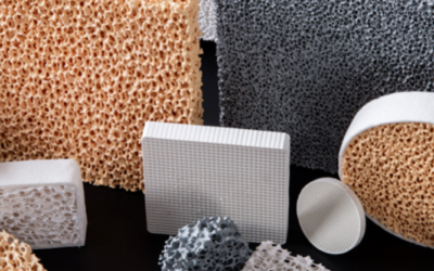
SiC ceramic foam filters are porous ceramic structures made to clean molten metal during casting. The material—silicon carbide—forms a three-dimensional open-cell network. Connected voids create pathways for metal to flow. Contaminants get trapped inside.
Think of it as a ceramic sponge that handles extreme temperatures. Between 75% and 95% of the filter’s total volume is empty space—some versions reach 90% porosity. Just enough ceramic material remains to form a web-like skeleton around the empty chambers.
The density stays low: 0.3 to 0.8 g/cm³. This lightweight build still works great. The open-cell design lets manufacturers control pore size and spacing based on what they’re casting. More surface area gives better filtration and stronger catalytic reactions.
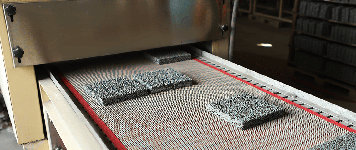
Manufacturing Process: From Foam to Filter
Production starts with polyurethane or cellulosic foam. This organic foam gets dipped into a ceramic slurry. The slurry contains silicon carbide, colloidal silica, and one critical ingredient: at least 10% fumed silica.
That fumed silica component does more than you’d expect. It creates smoother bonding and a more continuous matrix structure. Filters made with fused silica or alumina can’t match this. Real foundry data proves it—workers cut filter replacement frequency in half after switching to SiC foam filters with proper fumed silica content.
Compression comes next. You squeeze the coated foam to push out excess slurry. The fiber web stays coated. This step increases “flow path twists and turns.” The molten metal has to navigate a more complex maze.
Heating removes the organic polymer at 1180°C for 10 minutes. Pure ceramic foam structure remains. Some manufacturers use a different method called carbothermal reduction. Silicon reacts with carbon at high temperatures. This forms silicon carbide on the spot.
How the Structure Creates Clean Metal
The twisting flow path drives filtration performance. Molten metal gets pushed through the porous framework. Unwanted particles hit pore walls and stick. Clean metal exits the other side.
The filter stays intact at temperatures above 1400°C—way beyond what standard ceramic filters handle. It keeps its strength under constant pressure from flowing molten metal. Chemical resistance keeps the structure stable. Even corrosive casting alloys can’t break it down.
How SiC Filters Trap Metal Impurities (Inclusion Removal Mechanism)
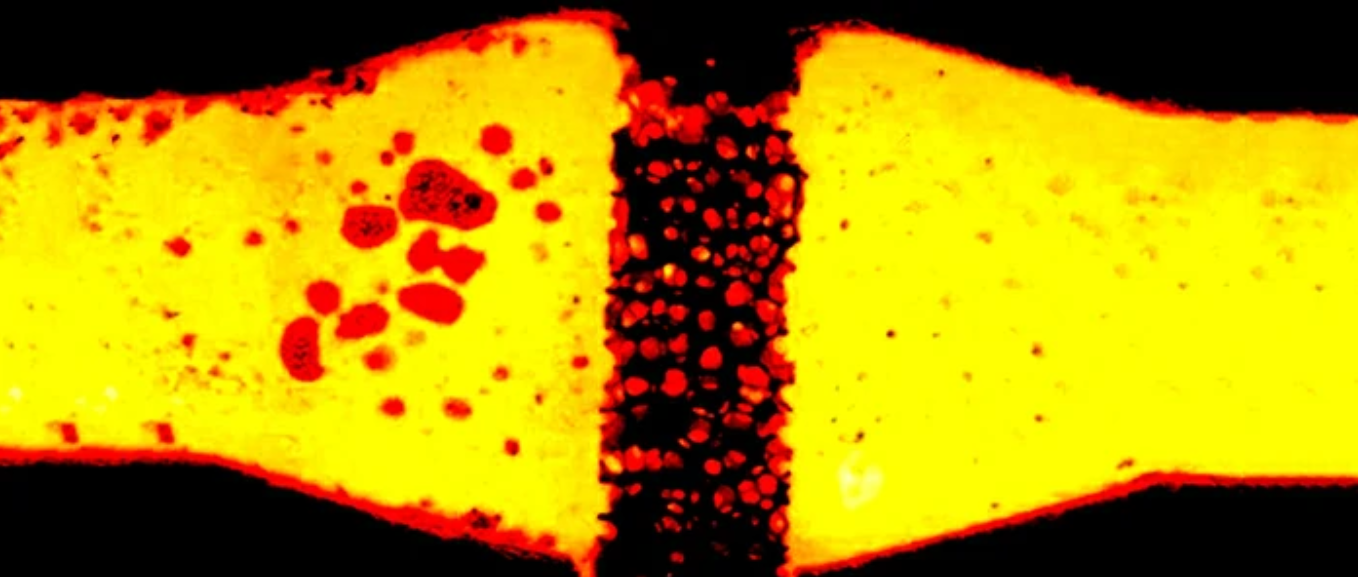
Three different filtration processes work at once inside every SIC ceramic foam filter. Each one targets different contamination types and particle sizes. Together, they create a multi-stage cleaning system that beats single-method approaches.
Mechanical Sieving: The First Defense Line
The pore network blocks particles larger than the opening size. Any inclusion above 20 micrometers gets stopped at the filter entrance. This direct blocking works like a traditional screen. It operates at temperatures over 700°C.
PPI ratings set the filtering precision. A 10 PPI filter catches particles above 50 micrometers. Step up to 20 PPI. The threshold drops to 30 micrometers. The tightest spec—30 PPI—captures anything larger than 20 micrometers. All three grades achieve 95% or better removal rates within their target size ranges.
Sand particles from mold erosion measure 20 to 100 micrometers across. Refractory debris exceeds 20 micrometers too. Both get stopped cold at the filter surface. Metallic impurity compounds separate based on density differences and particle size. These include iron, boron, vanadium, aluminum, titanium, copper, manganese, tungsten, chromium, and nickel.
Cake Filtration: Building a Secondary Barrier
The largest trapped particles don’t just sit idle. They form a filter cake layer on the entrance surface. This cake becomes a second filtration stage. Smaller inclusions that would slip through the pores now get caught in the cake structure.
Oxide films measure 1 to 20 micrometers thick. The initial mechanical sieving captures the bigger films. The growing cake layer traps smaller and smaller oxide pieces as molten metal continues flowing. Slag components build up the cake thickness. These include aluminum oxide, magnesium oxide, and other non-metallic waste from the Casting process. This self-boosting system improves filtration efficiency over time.
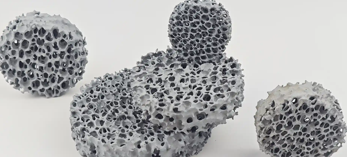
Depth Filtration: The Internal Trap Network
Contaminants that get past the surface are captured deep inside the porous structure. SiC foam filters maintain 10 to 20 percent residual porosity throughout their internal skeleton. This creates countless internal dead-end chambers. It also creates winding pathways.
Surface chemistry drives adhesion strength here. Silicon carbide’s high hydrophilicity creates better wetting with molten metal. Clean grain boundaries with zero glass or metal phases generate stronger adhesion forces on passing impurities. alumina filters can’t match this. Their lower thermal stability and chemical resistance lead to weaker particle capture.
The evaporation-condensation sintering process maximizes internal surface area. More contact points mean more opportunities to trap particles. These particles travel through the depth of the filter.
Real-World Performance Numbers
6063 Aluminum Alloy casting data shows clear improvements. Extrusion speed increased 20 percent after implementing SiC foam filtration. Productivity jumped 15 percent in the same facility. Extrusion force requirements dropped 3 percent. This reduces wear on equipment and energy use.
Foundries filter the complete melt volume through one filter plate. Each filter handles one full pour before replacement. The system slots into existing infrastructure. Major modifications aren’t needed. A steel shell with refractory lining provides the mounting framework. It sits between the launder and casting well.
Custom PPI specs run from 7 to 45. This depends on alloy composition and cleanliness requirements. Higher PPI grades suit aluminum and copper alloys with finer inclusion sizes. Lower PPI works for cast iron. Larger debris is the main contamination issue there.
How SiC Filters Cut Down Turbulence and Gas Defects
Chaotic molten metal flow creates two problems in casting: turbulence and trapped gas. Both ruin your final product quality. Standard filtration can’t fix these issues.
SiC Ceramic foam filters tackle these problems through their internal design. The twisted pathway forces molten iron through many directional changes. This breaks up turbulent flow patterns before they reach the mold cavity. Violent, swirling metal enters. A steady, controlled stream exits.
The Physics Behind Flow Stabilization
The connected pore network does more than trap particles. It controls flow speed with precision. Crossflow speed increases wall shear-stress inside the filter passages. This cuts down fouling. Plus, it boosts permeate flux. Test data shows flux improvements reaching 2 times baseline rates with Crystar® 0.60 µm specs.
Tortuosity measurements tell the real story. SiC membranes show a tortuosity factor of just 1.20—among the lowest in ceramic filtration. Add porosity above 40 percent. You get ideal conditions for turbulent flow control. Uncoated filters process metal at 368 L/m²/h. Coated versions stabilize this to 165 ± 3 L/m²/h. The reduction isn’t a limit. It proves controlled slowdown that stops destructive turbulence.
Gas Defect Prevention Through Bubble Capture
Hydrogen and nitrogen bubbles dissolve into molten metal during melting. Traditional pouring systems let these gases pass freely into molds. They form porosity defects. These defects wreck mechanical properties.
The SiC foam structure gives attachment surfaces throughout its depth. Gas bubbles hit pore walls and stick. The high surface area creates thousands of nucleation sites. Dissolved gases turn back to bubble form here. They escape upward—away from the casting stream.
Air entrainment drops the moment metal passes through the filter. The smooth flow pattern after filtration stops atmospheric oxygen from getting pulled into the metal stream. SiC membranes hit permeate flux rates of 450 L/h/m²/bar at 2 bar transmembrane pressure. That’s 2.5 times higher than oxide ceramic alternatives. Higher flow with lower turbulence means less time for air exposure.
Downstream Protection and Yield Impact
Stable, low-speed metal flow protects sand molds from erosion. High-speed turbulent streams tear loose sand particles. These particles become inclusions. The controlled exit speed from SiC filters stops this erosion completely.
Casting yields improve because defect rates drop. Less rework means less wasted metal. Fewer scrapped parts means better material use. Permeability recovery hits 100 percent after cleaning with NaOH, surfactant, and H₂O₂ solutions. Filters keep performance across multiple production cycles with proper care.
Selecting the Right SiC Filter Specifications
Filter specs decide if you get clean castings or expensive rejects. Three key choices shape your results: pore density, physical size, and material grade. Get these wrong and even top-quality SiC filters won’t perform well.
Matching PPI to Your Metal Type
Pores Per Inch (PPI) controls what size particles get caught. Standard specs run 10, 20, and 30 PPI. Custom orders span 7 to 45 PPI for special work.
10 PPI works for iron casting. Large refractory chunks are the main problem here. The wider openings stop early clogging. Flow rates stay high through complete pours.
Aluminum and copper need tighter filtration. 20 PPI captures oxide films in the 30-micrometer range. This spec balances particle capture with good pressure drop.
30 PPI targets fine particles below 20 micrometers. Precision aluminum castings need this grade. The trade-off? Slower flow and higher pressure needs. All three grades deliver 95% removal efficiency or better for particles above their size limit.
Calculating Filter Dimensions
Physical size depends on pour weight and metal flow speed. A 50×50×22 mm filter suits small-batch work. General production runs use 100×100×22 mm plates. Large industrial pours need 300×300×22 mm sizes or bigger.
The 22 mm thickness stays standard across sizes. This depth gives good filtration without too much pressure drop. Thicker filters trap more particles but slow flow rates. Thinner ones risk contamination breaking through.
Custom sizes solve unusual gating system needs. Tell us your molten metal type, pouring temperature, and target filtration level. Manufacturers figure out the best size from these details.
SiC Filter Performance in Different Casting Processes
Each metal casting type needs its own filtration setup. Aluminum runs at 700-800°C. Steel pours at 1600-1620°C. Iron sits between them at 1400-1450°C. Match your filter spec to the metal’s working temperature and particle size.
Pore Density Matching by Metal Type
10 PPI filters handle ductile iron, large Gray Iron, and steel casting. These metals carry bigger debris pieces. Wide pore openings stop early clogging during high-volume pours. Steel liquid hits the highest working temperature—1600-1620°C—with a melting point ceiling of 1700°C. Sustaining time drops to just 5 minutes. Gas evolution peaks at 60 cm³/g.
20 PPI works across gray iron, malleable cast-iron, and non-ferrous alloys. This middle-ground option catches oxide films. Flow rates stay good. Iron liquid runs cooler at 1400-1450°C. It sustains filtration for 10 minutes with gas evolution at 8 cm³/g—87% lower than steel.
30 PPI targets precision work in gray iron, malleable cast-iron, and non-ferrous alloys. The tight pore spacing catches particles below 20 micrometers. Copper and aluminum both show 10-minute sustaining times with 6 cm³/g gas evolution. Aluminum’s 700-800°C working temperature makes it easier to filter. Thermal stress stays low.
The 3-25 PPI range delivers the highest total material throughput for iron and iron-based alloys. Production foundries running continuous pours get the best ROI here.
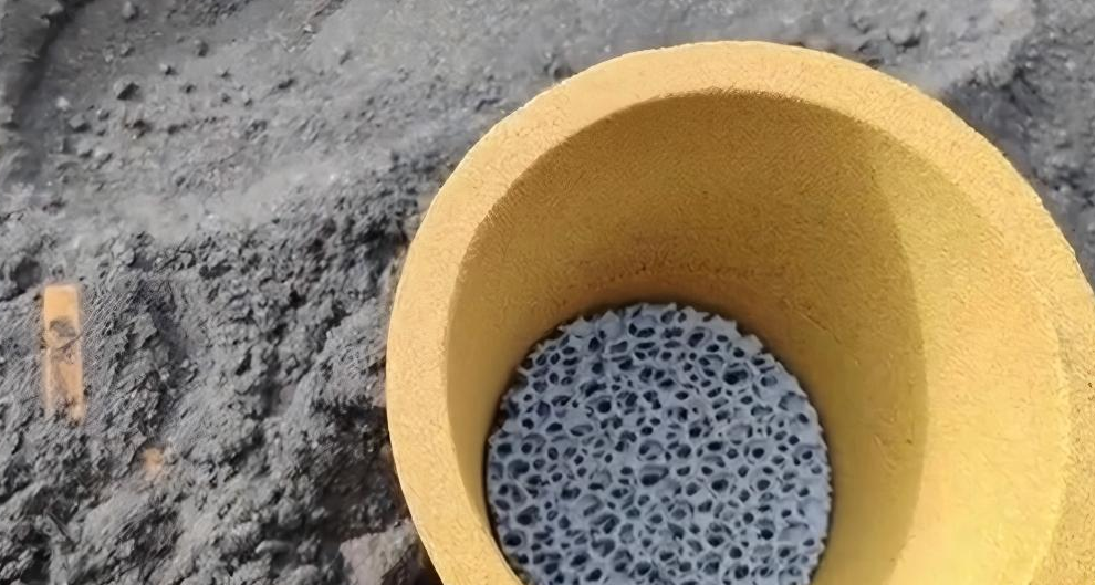
Installation Position and System Design
Position filters close to the casting. The working area of your filter should be 4-6 times the choked flow section in your gating system. This ratio keeps pouring speeds safe. Flow control protects filter strength. Metal stream velocity stays steady.
Skip the dirt trap in your gating system. A simple, direct path improves yield. The filter handles contamination removal. Extra flow interruptions create turbulence. You’ve already paid to get rid of that.
Cup-style Mesh filters suit small-size cast steel in Investment casting. These run at 700-1620°C for 80 seconds. SiO₂ composition stays above 96%. Volume weight ranges from 255-380 kg/m³. Tensile strength exceeds 16 kg per 4 ends. Gas evolution stays under 60 cm³/g—matching steel liquid specs.
Aluminum-Specific Preheating Protocol
Preheat both filter box and filter plate for aluminum casting. Make them uniform. Match the temperature of your liquid aluminum. Normal starting pressure head runs 75-150 inches. Molten aluminum starts passing through. Pressure head drops below 25 inches. Then it rises as the filter cake builds.
Remove the filter board right after filtration completes. Clean the filter box fast. Aluminum oxide buildup hardens quick. It gets hard to remove once it cools below 300°C.
Why Reuse Doesn’t Work
Filter cake builds up fast. Trapped particles create a second filtration barrier. But flow capacity drops. Permeability falls 35% by the end of a standard aluminum pour. Pull the filter out. Let it cool. The cake layer hardens. Oxide films and metal compounds lock into the porous structure.
Chemical cleaning exists. Sodium hydroxide solutions dissolve some oxide buildup. Hydrogen peroxide breaks down organic contaminants. Test data shows 100% permeability recovery after strong cleaning cycles. But here’s the problem—cleaning takes over 2 hours per filter. Labor costs kill any savings from reuse. Plus, the structure weakens. Heat cycling damages grain boundaries. Filter failure during the second pour is too risky compared to the material cost saved.
Other industries show the same pattern with refillable systems. Glass bottle reuse works because cleaning infrastructure spreads across dense collection networks. Short-trip glass bottles hit 91% recovery rates with 5 to 20 uses per unit. Filtration can’t do this. Each casting operation runs on its own. Centralized filter cleaning doesn’t work.
Common Installation Mistakes and Best Practices
Filter box prep fails more castings than bad filter specs. Foundries rush setup. Metal quality drops. You can fix installation errors with simple attention to detail.
Preheating: The Most Skipped Step
Cold filter boxes crack sic filters before metal touches them. A 700°C aluminum stream hits a 20°C filter. Instant fractures happen from thermal shock. The ceramic breaks down. Contaminants pass right through.
Preheat the complete filter setup. Match your molten metal temp. Aluminum needs 700-800°C preheat. Iron requires 1400°C. Steel pushes to 1600°C. Use the same furnace that holds your metal. Let the filter box sit for 30 minutes at minimum.
Half-heated setups cause another problem. The filter plate heats in an uneven way. One side grows faster than the other. Stress builds inside. The filter cracks during the pour—not before. You won’t spot the failure until defects show in finished castings.
Sealing Gaps That Let Metal Bypass
Metal finds the easiest path. A 2mm gap between filter and frame lets 15-20% of your pour skip filtration. That dirty metal reaches your mold. Your expensive sic filter just sits there doing nothing.
Use ceramic fiber gaskets around the filter edge. Compress them to 50% of original thickness during setup. This makes a complete seal. Check for gaps with a flashlight behind the installed filter. Light passing through means metal will too.
Refractory cement works for permanent setups. Put a 3mm bead around the filter seat. Press the filter in while the cement stays soft. Let it cure for 24 hours before the first pour. One foundry cut defect rates by 12% just by fixing bypass gaps.
Position and Pressure Head Errors
Filters too close to the sprue create flow problems. Mount your filter at least 6 inches downstream from the metal entry point. This gives flow time to settle. Wild streams damage filter structure. They cut particle capture rates.
Starting pressure head matters for aluminum. Begin with 75-150 inches of head pressure. Too low and metal won’t push through the pore network. Too high and you risk filter breakthrough. Dirty metal forces past the ceramic before proper filtration happens.
Watch pressure drop during the pour. Normal flow shows head falling to 25 inches as flow starts. Then it climbs back up as filter cake builds. Sharp pressure spikes mean clogging. High pressure that stays steady after the initial drop? That signals bypass flow around the filter edges.
Filter Size Errors
Your filter working area needs to be 4-6 times larger than your gating system’s choked flow section. Small filters create too much flow speed. Metal streams above 0.5 m/s eat away the filter surface. Silicon carbide particles break loose. They become dirt in your casting.
A 2-inch diameter sprue needs a 100×100mm filter at minimum. Scale this ratio for larger pours. Small filters also clog faster. Pressure needs jump. Pour times stretch out. Quality drops as metal temp falls during long filtration.
Timing the Filter Board Removal
Aluminum oxide hardens fast after pouring stops. Remove the filter board within 90 seconds of pour end. Wait longer and oxide buildup glues the filter to its frame. You’ll damage the frame trying to pull it out.
Clean the filter box right away. Dried aluminum oxide at room temp needs mechanical grinding to remove. Fresh oxide at 300°C wipes away with basic tools. This 2-minute cleanup step stops 30 minutes of repair work before your next pour.
Steel and iron give you more time. Their oxide mixes stay softer longer. But the same rule works—faster removal means easier cleanup and faster return to production.
Conclusion
SiC ceramic foam filters aren’t just another foundry accessory. They make the difference between acceptable castings and exceptional ones. These filters trap inclusions, smooth turbulent flow, and eliminate gas-related defects. You get real improvements in casting integrity, surface finish, and mechanical properties. This boosts your bottom line.
The data proves SiC ceramic foam filters improve metal casting quality. That’s settled. The real question? Are you optimizing their performance? Proper specification selection matters. So does correct installation. Strategic placement in your process flow counts too. Get these variables right. Defect rates drop. Yield climbs. Customer satisfaction goes up.
Audit your current filtration setup. Compare it against the best practices outlined above. Find your most problematic casting defects. Match them to the right filter specifications. Run controlled trials. Track your scrap rates. Measure your cost per good casting. Let the numbers guide your adoption strategy.
Your next great casting starts with the filter you choose today.