Sand has been shaping metal for over 3,000 years. Today, the process still powers 70% of all metal castings made worldwide. Yet most people who specify sand cast parts have never seen a mold packed, a cavity filled, or a finished part pulled from the sand. That gap costs real money — wrong tolerances, preventable defects, supplier miscommunications.
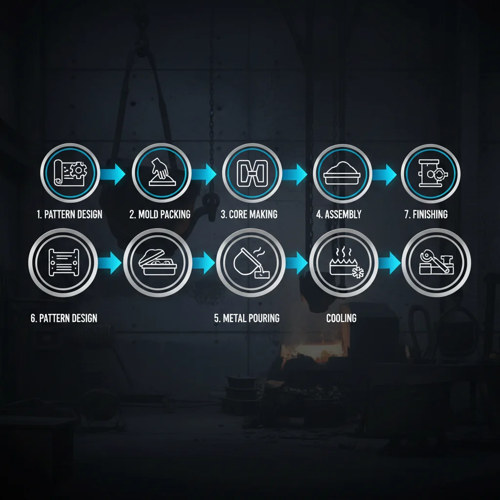
What is Sand casting, and how does mastering its seven core steps separate a flawless part from an expensive scrap heap? This guide breaks it all down — from pattern design through final finishing. You’ll walk away with working knowledge that changes how you buy, specify, and evaluate cast metal components.
What Is Sand Casting?
Sand casting is simple at its core. Pack sand around a pattern. Remove the pattern. Pour molten metal into the cavity left behind. Let it solidify. Break the mold open and pull out your part.
That’s it. That’s the whole idea.
The technical definition: a metal casting process where molten metal fills a mold cavity formed from packed and bonded sand, then cools and solidifies — also called sand molded casting. But that definition won’t tell you what makes it work, or fail.
The sand itself is what matters most. Not all foundry sand behaves the same way. Here are the three types you’ll run into most often:
-
Green sand — silica, bentonite clay, coal dust, and water. The industry workhorse.
-
Resin-bonded sand — hardened with chemicals, tighter tolerances, cleaner surfaces.
-
Facing sand — the specialized layer pressed against your casting, built up 30–100 mm thick.
The sand surrounding that facing layer? Plain backing sand — cheap filler, no special additives, just structural bulk.
Every property of that sand mix — its heat resistance, airflow capacity, and how well it breaks apart after casting — either supports your part or works against it.
How Sand Casting Works: Core Components You Must Understand First
Six distinct components do the actual work inside a sand casting operation. Miss one, misunderstand one, and your part pays the price.
The Pattern comes first. It’s built larger than your final part — that extra size accounts for the shrinkage metal goes through as it cools. Vertical walls carry a draft angle, a slight taper. That taper lets the pattern pull free from packed sand without tearing the mold wall. Wood or plastic works fine for low-volume runs. Aluminum patterns cost more but outlast everything else.
Cope and Drag are the upper and lower mold halves. The cope carries the feeding channels. The drag holds the cavity base. Alignment pins lock both halves inside a flask. That connection defines the parting line — the seam where both surfaces meet.
Cores handle the internal geometry. Hollow passages, recessed pockets, undercuts — none of that happens without a core. Three types dominate:
-
Shell cores — fine AFS-graded sand plus resin, blown into a heated core box running at 210–250°C
-
Cold-box cores — 50 AFS sand hardened by a triethylamine gas purge inside a sealed box
-
Hand-rammed cores — 75 AFS sand, packed by hand, fast to produce but limited to simpler shapes
The Gating System controls how metal moves. Channel dimensions set the fill speed. Push flow higher and non-fills drop — but turbulence climbs. Three common configurations:
-
Ring runner — spreads metal at a consistent rate around the cavity
-
Kalpur — single-point pour through a cup, filter, and insulating sleeve that keeps metal fluid longer
-
Bottom-fed (3-part) — metal enters from below, cutting turbulence where it matters most
Risers sit above the cavity as planned reservoirs. The casting cools and shrinks. Metal pulls back from the riser to fill that gap. That’s the difference between a solid part and a shrunken void.
One property ties all of it together: permeability. Sand must exhaust gases as metal fills the cavity. One cubic centimeter of trapped water turns into 1,600 cubic centimeters of steam — fast. A mold that can’t breathe doesn’t survive the pour.
Step 1 — Pattern Design & Production: Where Precision Begins
The pattern is a promise. It tells the sand what shape to become — and every millimeter of error shows up later, in metal. At that point, fixing it costs ten times more.
Pattern production has changed a lot. CNC machining and CAD/CAM integration now deliver tolerances within ±0.001″. Hand-built wooden patterns could never hold those dimensions with that kind of consistency. What once took days of skilled manual work now moves straight from a digital file to a finished pattern.
That precision matters for one specific reason: shrinkage allowance. Metal contracts as it cools. Your pattern needs to be built oversized — around 1–2% larger, depending on the alloy — so the final casting lands on the dimensions your engineering drawing specifies.
Three pattern materials dominate foundry floors:
-
Wood — fast and cheap, suitable for prototypes and short runs, but warps under repeated use
-
Plastic (epoxy/polyurethane) — good dimensional stability, moderate volume capacity
-
Aluminum — expensive upfront, but holds tolerances across thousands of pulls
Modern CAD-driven workflows also cut out a silent killer: manual grading errors. Software locks in consistent geometry across every pattern iteration. Dimensional drift does not accumulate. The mold you pack on day one matches the mold you pack on day five hundred.
Quality does not live in the pour. It starts here.
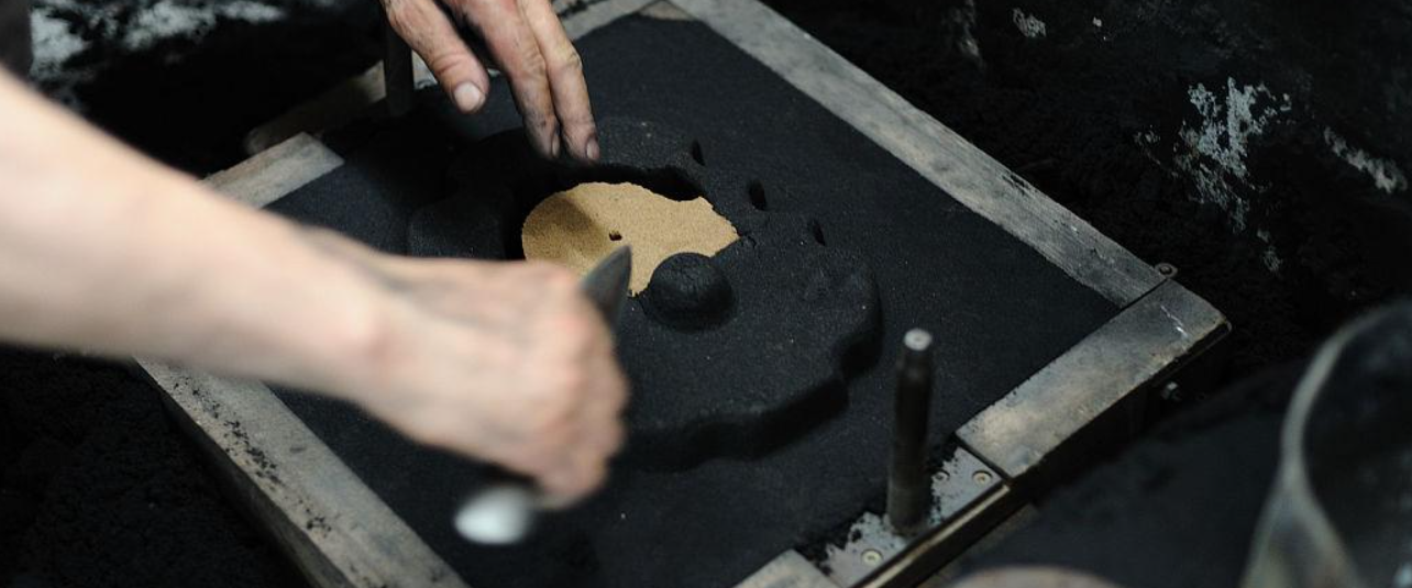
Step 2 — Mold Cavity Formation: How to Pack Sand Without Defects
Pack sand wrong, and the mold tells you — just not until molten metal is already inside it.
This is where most defects are born. Not in the pour. Not in the pattern. Here, in the packing. Small mistakes get buried under layers of sand. You won’t see them until it’s too late to fix them without serious cost.
The process runs in sequence, and the sequence matters.
Fine sand goes in first. Push it against the pattern surface to capture every edge and every contour detail. Coarse backing sand follows in layers behind it. Compact each layer before adding the next. That coarser material isn’t just filler. It’s the exhaust system. It lets gases escape during the pour instead of building pressure inside the cavity.
Compaction: Getting the Density Right
How you compact the sand determines what survives the pour.
Four methods are in common use:
-
Pneumatic ramming — the standard approach. It removes gaps and builds consistent firmness across the mold body
-
Vibration — applied after the cope joins the drag. It settles sand into voids that ramming misses
-
Mechanical compaction — different tooling, same result. Firms the sand without ramming
-
High-pressure molding — what modern automatic lines use. Jolting and vibration handle pre-compaction first. Then compressed air-powered pistons finish the job
Under-compact and you get a soft mold that shifts. Over-compact and permeability drops — gases have nowhere to go.
Defect Prevention: What Goes Into the Sand Mix
You can blend up to 5% reducing agents into the molding material to prevent surface defects. Common choices include coal powder, pitch, creosote, and fuel oil. These additives create a thin gas layer at the cavity wall during the pour. That gas stops liquid metal from sticking to sand particles. The result: less burn-on, less metal penetration, and better surface finish — all in one step.
One hard rule: don’t use reducing agents with steel. They carburize the metal. The fix creates a worse problem than the defect it prevents.
Once the sand is packed, pull the pattern out with care. The cavity left behind sits inside a “green” mold — still moist, not yet hardened. That mold closes back up and dries before it receives metal.
The cavity is now the part. Everything from this point forward is just filling it.
Step 3 — Core Making & Placement: Achieving Internal Cavities
Internal geometry doesn’t form itself. Every hollow passage, recessed pocket, and threaded boss in a sand casting exists because someone built a core. A core is a solid, shaped insert placed inside the mold cavity before the pour.
The core holds the space where metal cannot go. Molten metal fills around it. The casting cools. The mold breaks apart. Then the core gets removed — leaving behind the internal feature it once occupied.
Three variables define whether a core performs or fails:
-
Composition — shell cores use resin-bonded sand cured at 210–250°C for tight tolerances. Cold-box cores harden through gas purge. Hand-rammed cores suit simpler geometries and work fast.
-
Placement accuracy — a core that shifts during the pour produces off-center holes, uneven wall thickness, and scrapped parts. Even a small shift causes real damage.
-
Support — cores sit inside the cavity using chaplets (metal supports) or core prints built into the pattern geometry.
One rule governs placement above everything else: the core must stay put. Buoyancy is real. Molten metal pushes upward. An unsupported or under-anchored core floats, tilts, or shifts — and your internal cavity moves with it.
Get this step right, and complex internal geometry becomes repeatable. Get it wrong, and no amount of finishing work saves the part.
Step 4 — Mold Assembly & Preparation: The Last Defense Before Pouring
The cavity is ready. The cores are placed. Now everything locks together — and this is where a lot of otherwise good work falls apart.
Mold assembly isn’t glamorous. No sparks. No heat. But it’s the last checkpoint before molten metal takes a shape. Three to five days of preparation go into getting this stage right.
The sequence runs tight:
-
Fit all components together — cope, drag, cores, and flask must align with no gaps. A slight misalignment at the parting line produces flash, dimensional shift, or worse
-
Install ejectors — these handle part removal after the metal solidifies. Wrong positioning now means extraction damages the casting later
-
Test cooling systems — thermal control during solidification shapes grain structure, shrinkage behavior, and surface quality. Get it wrong and the part fails from the inside out
No shortcuts hold up against liquid metal at 1,400°C.
This step runs inside serious industrial infrastructure. The U.S. sand casting and mold manufacturing sector alone spans 1,364 facilities, employs 34,901 workers, and represents a $6.8 billion market. Assembly preparation isn’t a backroom task. It’s a precision discipline at full industrial scale.
Everything after this point is a result of what you did here. Assembly is where you control the outcome.
Step 5 — Pouring Molten Metal: Temperature, Speed, and Control
The pour is unforgiving. Get the temperature wrong by 20 degrees and you’re not making a part — you’re making scrap.
Every alloy has its number. Steel runs between 1,640–1,680°C at tapping. Aluminum melts at 660°C but pours hotter. You need 50–70°C above the crystallization temperature to keep the metal fluid long enough to fill every corner of the cavity. Too hot and you get oxidation, gas absorption, and a brittle final structure. Too cold and the metal stiffens mid-fill. That produces misruns — incomplete castings that look almost right but are no good to anyone.
Speed Is a Variable, Not an Afterthought
Pour rate shapes the outcome just as much as temperature does.
-
Pour too fast — uneven cooling, hot spots, internal cracks, cold shuts where two metal fronts meet and refuse to fuse
-
Pour too slow — premature solidification, incomplete fill, surface defects
-
Thin sections need speed. Without it, the metal chills before the cavity fills
-
Thick sections need patience. Rush them and turbulence tears the mold wall
In continuous steel casting, cycle time runs 24–25 minutes. Low-temperature conditions need a nozzle upgrade — from φ16.5mm to ≤φ18mm. That shortens the cycle window and keeps tundish temperature stable. Smaller nozzle means a smaller margin for error.
What Monitoring Looks Like in Practice
You don’t guess at temperature. You measure it with an immersion pyrometer. Check it at set intervals throughout the pour — not just at the start.
Keep tundish temperature within the target band (±10°C of line A/B) and qualified casting rates push above 90%. Slab defect rates drop below 0.01%. Those aren’t goals. That’s what steady temperature control delivers on a real production floor.
The pour is the moment everything either holds or breaks. Temperature. Speed. Control. Get all three right, or the whole thing falls apart.
Step 6 — Cooling & Solidification: Why Patience Determines Quality
The metal is in. Now the real work begins — and it happens out of sight, measured in degrees per second.
Cooling rate isn’t a passive variable. It’s a design decision that rewrites the mechanical properties of your part from the inside out.
The numbers tell a clear story:
-
Push cooling from 0.15°C/s to 1.5 × 10⁵°C/s and hardness climbs from 80.9 HB to 125.7 HB
-
Tensile strength jumps from 189.3 MPa to 282.5 MPa
-
Elongation goes up by close to 2×
What drives all of it? Secondary Dendrite Arm Spacing (SDAS).
Slow cooling produces SDAS of 84.1 µm — coarse, weak, and uneven. Rapid cooling brings that down to 0.82 µm. Smaller spacing gives you finer grains, more even element distribution, and a tighter, stronger part overall.
Faster isn’t always the right call, though. Rapid solidification stretches the freezing range. In A356 alloys, the solidus temperature drops 48–75°C, pushing the solidification interval out to 151°C. A wider window like that raises hot-tearing risk. Your gating and riser system needs to account for it — or you pay for it in defects.
Controlled, deliberate cooling isn’t weakness. It’s the final quality gate.
Step 7 — Demolding, Finishing & Sand Reclamation: From Raw Casting to Final Part
The casting is solid. Now comes the part most process guides rush past in two sentences.
Breaking the mold open is simple. Mechanical vibration shakes the sand loose. The casting drops free. Then workers knock out or shake apart the cores. What comes next is harder.
Finishing transforms a raw casting into a usable part. Workers cut away gates and risers. They grind down parting line flash. They blast off surface scale. Every one of those steps adds time, cost, and room for error — especially if the upstream work wasn’t done right.
The Sand Problem Nobody Talks About
Here’s a number worth thinking about: the average foundry dumps 8,000 tonnes of sand per year into landfill — with no reclamation at all.
MAT Foundry uses 4–5 tonnes of sand per tonne of metal cast. Scale that across global output and the waste numbers grow fast. World sand consumption already runs at 50 billion tons per year. India alone uses 750 million tons per year and is shifting hard toward reclamation — because virgin sand supply is running out.
Reclamation changes the picture. The process runs in three stages:
-
Mechanical — grinding strips binders and coatings; vibration sieves remove coarse dust
-
Thermal — heat burns off organic binders from no-bake and chemical systems
-
Wet — used alongside the others to push final sand quality higher
MAT Foundry’s secondary attrition unit at EURAC Poole has cut new sand purchases by 5,000 tonnes per year since 2022. Waupaca Foundry has restored 524,000 cubic yards of sand and gravel pits in Wisconsin using reclaimed material. Their Tell City plant ships 95,000 cubic yards to a Kentucky mine every year.
The market reflects this shift. Sand reclamation is on track to hit US$2.69 billion by 2030, growing at 6.1% CAGR. Foundry waste sand recycling is moving faster still — 12.4% CAGR through 2032.
Finishing closes the part. Reclamation closes the loop.
Conclusion
Sand casting isn’t complicated — but it punishes shortcuts.
Every step in this process, from pattern design to final finishing, is connected. Skimp on mold packing in Step 2, and you’ll pay for it in Step 6. Rush the cooling, and the defects you find in Step 7 become expensive scrap, not finished parts.
Successful casters treat each of the 7 steps as a system. Not a checklist. That’s the real difference.
You now understand what sand casting is and how the full process works. That puts you in a better position to make smarter decisions. Evaluating a supplier? You know what to look for. Designing your first pattern? You know where the risks are. Troubleshooting a recurring defect? You know which step to trace it back to.
Your next move: Pick one step from this guide. Look at how it’s being executed in your process right now. One weak link is all it takes to compromise the whole casting.
Master the steps. Control the outcome.