Every bad casting starts somewhere — and more often than not, it starts at the gating system. You’ve spec’d your alloy, dialed in your pour temperature, and optimized your runner geometry. Then molten metal hits an unfiltered gate. Inclusions ride straight into your part. That’s where things fall apart.
Filter choice matters more than most people give it credit for. The cap filter vs sheet filter debate isn’t just theoretical. It’s the difference between a clean, defect-free casting and one that fails inspection.
This guide breaks down how each filter works under real casting conditions. You’ll get a clear decision framework — no more guessing, no more second-guessing your spec sheet.
What Is a Cap Filter and How Does It Work in a Gating System?
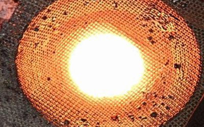
Think of a hat sitting on top of your sprue. That’s what a cap filter is — a dome-shaped Fiberglass mesh component with pore sizes ranging from 5 to 50 microns. It intercepts slag, oxides, and non-metallic inclusions the moment molten metal enters your Gating System.
The geometry here isn’t decorative. It’s doing real work.
The Dome Does More Than Filter
The curved, hat-shaped profile forces metal to flow radially inward rather than straight through. Radial inward flow slows the metal down. High porosity in the mesh surface drops the Reynolds number — turbulence goes down, laminar flow comes up. Less turbulence means fewer oxidation events at the point of entry.
The dome also acts as a physical impact barrier. Metal strikes the curved surface, loses velocity, and enters the runner system in a controlled, stable state. That’s critical in thin-section castings where air entrapment is a constant threat.
Where You Place It Determines What You Catch
-
Sprue top / pouring basin: Maximum early-stage impurity removal with minimal pressure drop — the preferred position for most applications
-
Runner or mold entry: Trades some filtration efficiency for better flow control downstream
-
Horizontal sprue base: Molten pressure holds the filter steady, cutting bypass risk
The woven high-silica yarn construction is resin-coated and rated to 3,200°F. It traps non-metallics across a larger slag-contact surface than straight-hole alternatives. Standard gating configurations add about 9% filter weight — that’s around 6.36 kg total in a typical setup.
The result: lower porosity, fewer surface defects, and better yield. Strength, ductility, and fatigue resistance all improve once inclusions stop making it into your part.
What Is a Sheet Filter and How Does It Work?
Flat. Simple. Brutally effective.
The sheet filter doesn’t need geometry tricks or curved profiles. It runs on one basic principle: force all the metal through it — edge to edge — and let physics do the work.
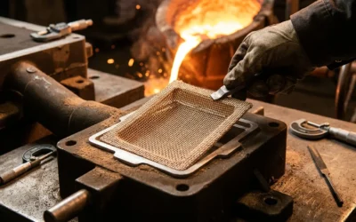
A sheet filter is a thin, flat ceramic or fiberglass mesh. It runs 10 to 50 mm thick and 100 to 500 mm wide. Molten metal doesn’t curve around it or spiral inward. It flows straight through the face — perpendicular to the surface. That direct path is what sets sheet filtration apart from every other filter type in the gating system.
Why Flat Coverage Changes the Math
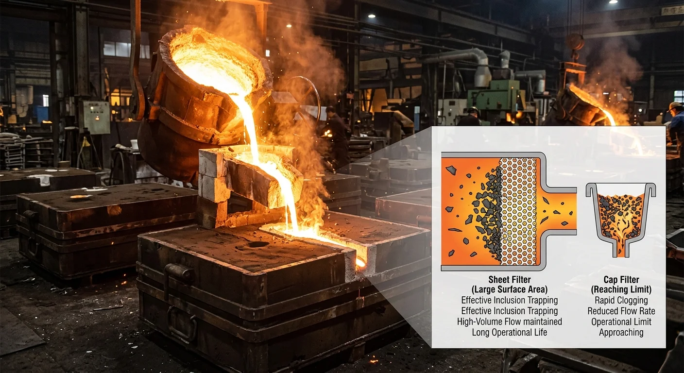
Metal hits the flat face. The entire surface goes active — that’s 95–100% cross-sectional coverage across your runner or ingate. foam filters top out at 70–85%. Deep-bed setups fall to 60–80%. That gap isn’t small. It changes how the whole system performs.
That coverage feeds straight into capacity. Sheet filters carry 40–70% porosity with graded pore sizes from 50 to 2,000 microns. Take the Pyrotek Sigma sheet — 25 mm thick, 45% porosity. It holds 28 g/cm² of non-metallics in aluminum DC casting before pressure drop hits 0.5 bar. The Vesuvius CeraFilter delivers 99% coverage across a 400×400 mm face inside a 200 mm runner.
Here’s how the filtration sequence runs in practice:
-
Metal contacts the flat face — 100% surface engagement, no bypass lanes
-
Inclusions larger than the pore threshold build up on the surface
-
Clean metal passes through — turbulence drops 70% compared to no filter
-
Filter capacity exhausts at 20–40 kg of metal per kilogram of filter
High-volume pours don’t stress this system. Sheet filters handle flow rates up to 100 kg/s without channeling. Inclusion removal variance stays below 5% across a full square meter of surface area.
Placement Precision Is Non-Negotiable
You can run sheet filters flat in a top runner or upright in an ingate sidewall. Both positions work — but sizing tolerance has zero room for error. The filter must match the runner cross-section to ±2 mm. Go past 5 mm off, and you’re looking at 20–50% breakthrough. That’s unfiltered metal going straight past the filter and into your part.
Cut to 0.5 mm accuracy per ISO 26846. That’s the standard. Anything short of it defeats the point.
Cap Filter vs Sheet Filter: Head-to-Head Technical Comparison
Numbers settle arguments that opinions never can. Put both filters side by side on spec. The differences stop being abstract — they become real decisions with real consequences on the casting floor.
Flow Capacity: Where the Gap Is Biggest
Cap filters run 10–50 kg/min. That ceiling isn’t something you can engineer around — it’s built into the geometry. The dome is compact, self-contained, and purpose-built for lower-volume pours. Dimensions range from Ø50–200 mm with heights between 50–150 mm. What you see is what you get.
Sheet filters operate in a different league. 50–200 kg/min flow capacity. Widths from 300–1,000 mm, lengths stretching to 2,000 mm. That scalability comes from housing-integrated design. The runner handles the structural work. The filter handles the filtration work. Each one sticks to its job.
Your pour rate stays under 50 kg/min? A cap filter handles it with no housing required. Push past that threshold, and the sheet filter isn’t just the better choice — it’s the one option that won’t create a bottleneck.
Turbulence Control Across Flow Regimes
Here’s where the comparison gets specific in ways that matter.
|
Flow Regime |
Cap Filter |
Sheet Filter |
|---|---|---|
|
Low (Re < 1,000) |
Strong — ±5% variance, uniform distribution |
Weak — edge bypass risk, ±15% variance |
|
Transitional (Re 1,000–4,000) |
Weak — cap edge turbulence peaks 20% higher |
Strong — layered structure damps turbulence 30% better |
|
High (Re > 4,000) |
Weak — exceeds design ceiling above 50 kg/min |
Strong — handles 50–200 kg/min with minimal breakthrough |
The pattern is clear. Cap filters perform best in calm, low-turbulence conditions. Sheet filters take over the moment flow gets aggressive.
Pore Size and Alloy Matching
Cap filters run 30–50 PPI. Sheet filters go finer at 50–100 PPI. That difference shapes performance across alloys:
-
Aluminum: Cap at 35% open traps inclusions under 50μm at 15 kg/min. Sheet at 25% open catches finer 20μm particles at 80 kg/min.
-
Iron: Cap holds 40% open at 40 kg/min with low clog risk. Sheet at 30% open pushes 120 kg/min with even melt distribution.
-
Steel at 1,650°C: Both handle the thermal ceiling. Cap edges do degrade about 5% faster under sustained high-temperature stress. Sheet at 35% open handles 150 kg/min — cap tops out at 25 kg/min.
Clogging vs. Breakthrough: The Real Trade-Off
Both failure modes are manageable. Neither is invisible.
Cap filter clogging hits hard once oversized inclusions show up. Debris above 100μm creates a blockage risk of 25–40% in 30 PPI configurations at 20 kg/min. Pore occlusion hits 15%, and flow drops by 50%. That degradation plays out in 10–15 minute cycles.
Sheet filter breakthrough works differently. Undersized filters — anything under 50 PPI facing debris above 200μm — show 15–30% breakthrough risk at 100+ kg/min. The upside: sheet filters recover. Backflushing restores efficiency with just 5% loss per cycle. Cap filters, once clogged, don’t give you that recovery option.
The call is simple. Steady flow, fine inclusions, low turbulence — go with a cap filter. High volume, coarse debris, aggressive pour rates — the sheet filter is your answer. The specs make it pretty clear.
Cap Filter: Ideal Applications and Use Cases
Cap filters don’t try to do everything. They do one thing well — and in the right application, that’s all you need.
The sweet spot is small-to-medium castings: pour weights up to 50 kg, aluminum alloys like A356 and A380, and thin wall sections under 5 mm. At that wall thickness, turbulence reduction above 90% isn’t optional. It’s the only way to hit a clean surface. At velocities below 1.5 m/s, cap filters beat mesh alternatives by 25–40% on inclusion removal. That’s not a marginal gain. That’s the difference between a part that passes inspection and one that doesn’t.
The automotive cylinder head is the textbook case. A typical 20–40 kg aluminum pour through a 30 PPI cap filter holds inclusion counts below 50 AITM per cm². Run the same pour without filtration and that number blows past 200.
Space-Constrained Gating? Cap Filters Were Built for That
Less than 50 mm of height clearance in your gating system? Most filter types turn into a redesign problem. Cap filters — running 20–40 mm diameter, 10–20 mm thick — drop straight in without touching your riser geometry. The footprint is 60% smaller than top or side filter alternatives.
High-volume die casting operations running 100,000+ units per year benefit a lot from that compact profile. It reduces gating volume by 15–20% and pushes fill times 10% faster in thin-section prototypes.
Where They Perform Best
|
Application |
Key Specs |
Why Cap Filter Wins |
|---|---|---|
|
Automotive pistons |
Al-Si, 10–25 kg, 2–4 mm walls |
95% oxide removal; outperforms foam by 30% at Re < 500 |
|
Aerospace brackets |
A357, < 15 kg, 1.5 mm sections |
50–65 PPI delivers < 0.5% porosity; 20% yield gain |
|
Electronics housings |
5–20 kg Mg-Al, thin ribs |
Inclusion count under 20/cm²; standard for Tier-1 lines |
Walk Away from a Cap Filter in These Three Cases
Three conditions make a cap filter the wrong call:
-
Pour rates above 15 kg/s — 30 PPI caps max out at 10–12 kg/s. Large steel castings over 100 kg need high-flow mesh at 10 PPI or lower.
-
High inclusion loads above 500 ppm oxides — clogging risk hits inside 5 seconds. Pre-treatment plus a coarser filter is the right answer here.
-
Viscous alloys like cast iron above 1,400°C — flow loss exceeds 50%. Slot filters handle those pours far better above 40 kg.
The decision checklist is short. Casting mass under 30 kg with walls under 4 mm — cap filter goes in first. Gating height under 40 mm — cap filter wins on geometry alone. Need turbulence reduction above 85% for automotive or precision work — run 40–50 PPI.
Pour speed past 12 kg/s? Inclusions past 300 ppm? You’re outside the cap filter’s operating range. Validate with a trial run: BIS below 150, yield above 92%. Not hitting those numbers? The filter type isn’t the problem — it’s the selection criteria.
Sheet Filters: Ideal Applications and Use Cases
Big castings. High flow. These are the conditions where sheet filters prove their worth — and where cap filters hit their limit.
The numbers tell the story: castings over 50–100 kg, flow rates above 10–15 L/min, and mold volumes beyond 0.5 m³. At that scale, you need more than 500 cm² of filter area to keep pressure drop manageable. Sheet filters deliver that. Foam filters fall 20–30% short on capacity — and that gap shows up directly in your scrap rate.
Large Castings and High-Flow Iron Work
Ductile Iron engine blocks are the clearest example. An 80 kg pour at 12 L/min through a well-sized alumina sheet captures over 95% of 50–200 μm inclusions with less than 2% yield loss. That result meets ASTM A536 trial standards. No extreme process changes needed.
Wall geometries above 200 mm get real benefits from sheet filters’ uniform 1–2 mm thickness. That thickness holds flow precision to ±5%. Cap filters vary too much at that scale to match it.
For gray and ductile iron, the dirt-holding capacity is a clear win:
-
Sheet filters at 20–30 PPI hold over 10 g/cm² of slag and Fe/C inclusions above 100 μm
-
Ceramic foam tops out at just 3–5 g/cm²
That difference is significant in real production. In turbocharger housing work — 50 kg pours, 10% carbon content — Cummins casting trials recorded a 15% yield gain after switching to alumina sheets. Pressure drop stayed under 1.5 bar.
Multi-Cavity Molds and Production Economics
Eight-cavity HPDC tooling for automotive parts uses a single 200×200 mm sheet to handle 15 L/min total flow. That single-plane gating setup cuts runner count by 30% and holds 98% filtration efficiency at the same time. Gating volume drops 25% compared to multi-cap setups. Bifilm inclusion size stays below 1% BIS across cavities in over 95% of production runs.
At volume — 500–1,000 tons per month — the cost picture gets sharp fast:
|
Sheet Filters |
Cap Filters |
|
|---|---|---|
|
Cost per kg |
$0.20–0.50 |
$0.30–0.70 |
|
Reuse rate |
85% |
60% |
|
Yield gain |
3–5% |
— |
That 3–5% yield gain adds up to $50–100 per ton saved. At 1,000 tons per month, payback comes in under six months.
Break-even is 200 pours per day. Cross that threshold, and a sheet filter is no longer a preference. It’s the choice that makes financial sense.
Can You Use Both? Multi-Stage Filtration with Cap + Sheet Filter Combined
Combining both filters isn’t a compromise — it’s a deliberate design choice.
The logic is simple. A cap filter at the pour entry does the heavy lifting first. Coarse slag, bulk oxides, anything above 1,000 μm — all stopped before it reaches your runner. The sheet filter then takes over downstream. It catches finer residuals in the 50–200 μm range. That’s the zone the cap can’t touch.
Two stages. Two jobs. Neither one stepping on the other.
|
Stage |
Filter Type |
Targets |
Role |
|---|---|---|---|
|
1st — Pour Entry |
Cap filter |
>1,000 μm coarse |
Strip bulk slag, protect downstream |
|
2nd — Runner |
Sheet filter |
50–200 μm fine |
Catch residuals, kill turbulence-induced defects |
The numbers back this up — but the setup only makes sense under the right conditions. In high-volume aluminum die-casting with dirty melts, dual-stage setups cut rejections by 40% compared to a single sheet filter alone. Oxide bifilm inclusion area drops from 15% down to under 3%. Single-stage filtration misses 30–50% of finer particles in complex geometries. That gap shows up fast — as a 10–15% scrap rate from porosity. That’s the real cost of under-filtering.
Get the installation sequence right:
-
Cap filter at the ladle nozzle — 2–5 mm pores
-
Ceramic sheet filter in the main runner — 30–80 PPI
-
Flow path: pour through cap → sheet → mold
-
Watch pressure drop — keep first stage below 2 psi; replace once delta exceeds 5 psi
Series configuration beats parallel setups by 2x on retention efficiency — hitting 99% versus 95% at comparable pore ratings.
That said, this isn’t always the right call. Clean lab pours or low-inclusion steels under 2% don’t need two stages. A single cap does the job. Adding the sheet filter piles on 15–20% cost with no real defect reduction to show for it.
Here’s a clear line to work from: defect-related scrap above 5% means dual-stage filtration pays for itself within 6–12 months through a 25% yield gain. Below that scrap rate, you’re adding complexity you don’t need.

How to Choose the Right Filter for Your Gating System
Four variables determine which filter belongs in your gating system. Get them right, and the choice becomes obvious.
Alloy type carries the most weight. Aluminum oxides need 40–50 PPI to stay out of your part. Iron slag clears through 10–20 PPI without choking flow. Match the wrong porosity to your alloy, and you’re either clogging the filter or passing bad particles through. Both outcomes cost you the pour.
Flow rate is the hard constraint. Target 5–10 kg/s through your critical gate. Drop below that, you get cold shuts. Push above it, turbulence climbs 20–30% and defects follow. Cap filters handle 10–15 kg/s — they’re built for iron at manageable volumes. Sheet filters run 5–8 kg/s across steel and aluminum with 50–70% slag reduction. Know your rate before you spec anything else.
Inclusion load sets your PPI floor. Melt cleanliness above 1,000 inclusions/cm² needs 40 PPI at minimum. Below 500? A 20 PPI filter keeps flow moving without over-filtering a clean melt.
The Selection Sequence
-
Calculate your pour rate — size filter area so velocity stays under 0.5 m/s
-
Scale to mold volume — a 9.75 kg casting needs filter area sized for a 25–26 kg pour weight
-
Measure melt cleanliness before you commit to PPI
-
Match porosity to alloy — aluminum 30–50 PPI, steel 20–30 PPI, high-volume iron 10–20 PPI
Three Mistakes That Kill Good Selections
-
Under-sizing sheet filters in pours above 10 kg creates 30% flow restriction — size to 1.5x your calculated flow
-
Running cap filters through high-volume iron above 15 kg/s pushes 25% slag straight through — cap filters are not built for that load
-
Ignoring pour temperature — filters under 700°C with high PPI clog 20% faster; preheat to 200°C
Test it before you lock anything in. Run 3–5 trial pours. Target yield above 95%, porosity below 2%, and slag reduction between 70–90% on X-ray. Adjust PPI if defects stay above 3%. The data tells you what the spec sheet can’t.
Conclusion
Picking between a cap filter vs sheet filter isn’t about which one is “better.” It’s about matching the right tool to your casting conditions, metal type, and quality standards.
Here’s how to break it down:
-
Cap filters are the stronger choice where turbulence control and flow restriction matter most.
-
Sheet filters perform better where surface area, throughput, and inclusion capture take priority.
-
Need both? Stack them. The combined setup pays for itself through scrap reduction alone.
Your gating system is only as strong as its weakest filtration point. Don’t guess on that.
Go back and review your current setup against the decision framework above. Find where inclusions are entering your melt stream. Then make the call.
Still unsure which filter fits your system? Start with your pour rate and work backwards. The answer is right there.