Ceramic filters serve critical roles across many industries. You’ll find them in water purification for developing regions, precision RF components, and foundry operations.
But picking the right filter can get confusing. Gravity-fed water purifiers work differently than high-frequency electromagnetic filters. Matching the right technology to your needs takes some knowledge.
This guide breaks down the main ceramic filter types. You’ll learn their specific uses and the technical specs that matter for your application. These filtration systems work at the molecular level. We’ll show you which contaminants they remove and the HS codes you need for international buying.
You’ll also get practical tips for choosing and maintaining your filters. This helps your investment perform well long-term. Whether you’re filtering drinking water in rural areas or removing metal impurities in industrial casting, you’ll know what to look for.
What Are Ceramic Filters and How Do They Work?
Ceramic filters use porous ceramic materials to trap contaminants. The pore sizes range from 0.1 to 0.5 micrometers (µm). These rigid filter walls come in solid cylindrical “candles” or ceramic housings. They create a mechanical barrier against suspended particles, bacteria, and cloudiness in water or air.
The Physical Barrier Mechanism
The 0.5 µm pore diameter acts as the primary defense system. Particles larger than the pore openings get blocked at the entrance or surface layer. Most bacteria measure 0.2 to 2 µm in diameter. So the 0.2–0.5 µm pore structure captures them with high efficiency.
This physical screening delivers greater than 99–99.99% bacterial removal in lab tests using E. coli indicator organisms. For larger parasites and protozoan cysts (around 1–5 µm), the removal rate reaches above 99.9%. Simple size exclusion does the job.
Multi-Stage Filtration Process
Deep filtration happens inside the ceramic structure itself. Multi-level pore designs trap particles at different stages. Finer outer layers catch smaller particles. Coarser inner channels handle larger ones. This setup works through:
-
Inertial impaction: Particles collide with pore walls at flow direction changes
-
Interception: Direct contact capture as particles follow flow streamlines
-
Brownian diffusion: Random particle movement causes wall collisions
-
Multiple contact points: Progressive capture throughout the pore network
After initial operation, a “filter cake” forms on the surface. This built-up particle layer refines the effective pore size. It boosts retention efficiency too. Turbidity levels in filtered water drop below 1 NTU (Nephelometric Turbidity Units) with quality cartridges and proper pretreatment.
Enhanced Composite Structures
Many modern ceramic filters add functional coatings for broader protection:
Silver or silver-ion (Ag/Ag⁺) layers get embedded in pore walls or applied as surface coatings. These additions prevent bacterial regrowth inside the filter body. They suppress biofilm formation too. The antimicrobial action extends cleaning intervals. Plus, it reduces recontamination risks.
Activated carbon cores or layers combine with the ceramic shell. This tackles chemical contaminants. The dual-layer approach handles both physical particles and dissolved substances like chlorine or organic compounds.
Industrial ceramic filter elements withstand operating pressures exceeding 3–6 bar. This depends on structural design. Pressure differentials or gravity head drive the filtration flow through these durable filtration systems.
Main Types of Ceramic Filters for Water Purification
Ceramic filters for water purification come in four basic designs. Each one fits different flow needs, installation spots, and budgets.
Candle-Type Ceramic Filters
Candle filters look like hollow cylinders. One end is closed, the other open. The porous ceramic wall has controlled pore sizes. Pore fractions run between 21.0–22.4%. Lab-grade units show maximum pore diameters from 5.7 to 15.2 μm.
Most commercial candles add silver for antibacterial power. This stops bacteria from growing back inside the filter. High-quality extruded ceramic candles offer strong mechanical specs:
-
Flexural strength: ≈14.35 MPa
-
Total porosity: 67.6%
-
Macroporosity: 53.40%
-
Linear shrinkage: 2.51%
Installation and Use
You mount these candles through tank lids or bases. Dirty water stays outside the candle. Clean water passes through the ceramic wall. It exits through a threaded stem into the clean chamber below.
Countertop gravity systems like Doulton, Aquacera, and British Berkefeld use them. These units usually hold 2–4 candles in the upper chamber. You can also use them in inline pressure housings for under-sink or countertop setups with carbon media.
Performance Metrics
A Doulton SS gravity unit with two ceramic candles flows at about 1.7 L/h. Each candle set handles around 2,600 gallons (9,840 L) before you need to replace it.
Lab-scale elements vary more. Flow rates range from 0.039–1.9 L/h based on what’s in them:
-
50:50 clay/sawdust disk: 1.9 L/h with 80% coliform and 100% E. coli removal
-
Optimized ceramic disk: 39 mL/h output, turbidity drops from 13 NTU to 0.45 NTU, TDS falls from 1,245 mg/L to 360–530 mg/L, fluoride reduces from 3.4 to 0.053 mg/L
Plan to replace each element after 2,000–3,000 gallons. Most makers suggest changing candles every 6–12 months. This depends on turbidity and how often you clean them.
Canister/Housing-Type Modules
Canister systems put ceramic elements in pressure-rated plastic or metal housings. They connect straight to plumbing lines for under-sink or whole-house use.
Pressure-Fed Flow Advantages
These units run on line pressure (1–6 bar) instead of just gravity. This gives you much higher flow than passive systems. A standard ceramic-plus-carbon under-sink setup delivers:
-
Certified capacity: 800 gallons
-
Flow rate: 1–2 gpm (3.8–7.6 L/min) under pressure
Multi-Stage Configuration
Canisters often work in series for full treatment:
-
Stage 1: Sediment/ceramic (1–0.5 μm nominal)
-
Stage 2: Activated carbon block (chlorine, organics)
-
Stage 3+: Specialty media (fluoride, lead, nitrate)
You’ll see them in under-sink drinking water lines, point-of-use well polishing for particles and microbes, and off-grid setups with pump-supplied pressure.
Gravity Pot-Type Systems
The classic gravity pot puts a porous ceramic pot or candle in an upper bucket. Water drains through gravity into a lower storage bucket. No pressure, no electricity—just simple filtration for remote or emergency use.
Specialized Ceramic Filter Products
CeraMetix® product lines catch contaminants that standard ceramic filters miss. The CeraMetix® 1025 uses a 2.5″ x 10″ sintered ceramic shell with AquaMetix® composite media inside. This two-layer setup removes fluoride, farm chemicals, and dissolved organics. Plus, it filters out physical particles.
Fluoride Reduction Technology
The 1025 model has fluoride-specific ion-exchange media built into its ceramic structure. It takes municipal water with F⁻ levels of 0.7–1.5 mg/L and brings it down to safe drinking levels. The manufacturer says it captures fluoride well. But official NSF test reports with exact reduction rates and total capacity aren’t available online. You’ll need to ask dealers for NSF/ANSI test documentation that shows:
-
Inlet/outlet fluoride concentrations (mg/L)
-
Test flow rates (L/min or gpm)
-
Total throughput volume before breakthrough
-
Percentage removal at capacity endpoint
Agricultural Contaminant Filtration
CeraMetix® Candle Super models focus on removing pesticides and herbicides. The 0.2–0.5 µm ceramic outer shell stops bacteria like E. coli (0.5–1 µm) and Vibrio cholerae (0.3–0.6 µm). Inside, activated carbon and selective resins soak up dissolved organics. This includes atrazine, simazine, and VOCs. Most units meet NSF/ANSI 42 (chlorine, taste, odor) and NSF/ANSI 53 (lead, VOCs, some pesticides). Check the specific contaminant codes on current NSF certifications. Make sure they cover your target pollutants.
Ceramic Filters in Electronics and RF Applications
Radio-frequency circuits need ceramic filters to pick precise frequency channels. They also block interference. These parts use high-permittivity ceramic materials (εᵣ ≈ 80–100). This lets you build small resonators for mobile networks, Wi-Fi modules, and broadcast gear.
Band-Pass Frequency Selection
Distributed ceramic resonators set their center frequency through size and dielectric constant. A coaxial ceramic resonator follows the quarter-wave rule:
l (mm) = 300 / [4 × f(GHz) × √εᵣ]
At 1 GHz with εᵣ = 90, the resonator shrinks to just 7.9 mm. Air-dielectric designs need much bigger quarter-wave structures at the same frequency.
High-Q ceramics with low loss tangent give you narrow bandwidth and steep roll-off. This keeps insertion loss small. Plus, it blocks nearby channels. The temperature coefficient τf stays within 0–10 ppm/°C for quality coaxial ceramic resonators. That means frequency drift of 0.01–0.1 MHz/°C at 1 GHz. Stable enough for fixed-tuned uses.
Frequency Segments and Use Cases
2.4 GHz and 5.8 GHz ceramic filters work for WLAN, Bluetooth, and ISM-band modules. SAW filters handle mass-market Wi-Fi below 2.5 GHz. Ceramic and LTCC filters take over where you need higher power handling and thermal stability. They also help with compact multi-function integration.
5G base stations use ceramic filter banks for sub-6 GHz bands. These modules stack multiple duplexers and triplexers. This shrinks front-end space and cuts insertion loss. Terminal RF modules use similar LTCC designs for mobile handsets.
TV tuners have ceramic IF filters at fixed intermediate frequencies like 38.9 MHz or 45.75 MHz. The narrow band-pass design pulls out the desired channel from nearby signals.
Automotive infotainment and telematics systems make up another big use area. Connected vehicle modules need ceramic filters rated for –40°C to +85°C operation. With 0–10 ppm/°C drift, a ceramic resonator shifts less than 0.13 MHz across the full 125°C car temperature range at 1 GHz.
Standard ceramic coaxial filters handle continuous input power around 10 W. This works for base-station transmitters and high-power RF modules. No thermal runaway or resonance shift.
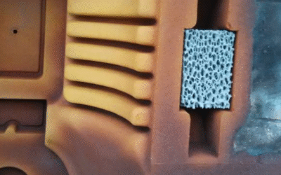
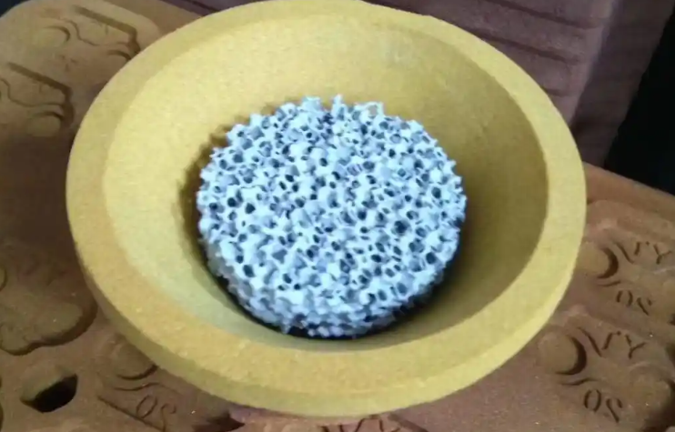
Ceramic Filters in Foundry
Metal foundries install foam ceramic filters in gating systems. These filters trap non-metallic bits before molten metal reaches the mold cavity. The filters catch oxide films, sand particles, and slag. Without them, these impurities create defects in finished castings. The foundry segment captured 34.6% of the global ceramic foams market in 2023. This makes it the largest application area.
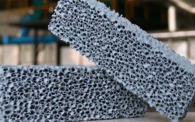
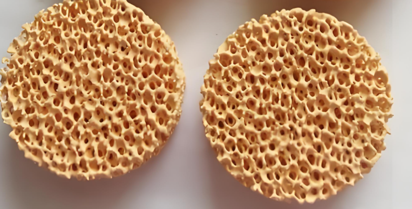
Filter Materials and Structural Design
Silicon carbide (SiC) foam filters lead foundry use. They offer great heat stability and chemical resistance. These filters handle molten metal temperatures above 1,500°C. They don’t break down or react with the melt. Alumina filters (like Flow-Rite from CoorsTek) balance heat resistance with controlled adhesion to metallic oxides. This balance helps the filter trap dirt without soaking up too much clean metal.
Zirconia foam filters work for special high-temperature alloys. Alumina or SiC would break down under these conditions. The steady cellular honeycomb structure beats random-pore foams. You get predictable flow patterns and better capture efficiency.
Performance Specifications by Metal Type
Cell density ratings run from 10 ppi (pores per inch) up to 30 ppi. Finer cells catch smaller bits. But they also create higher flow resistance. Foundries must match filter area to pouring rate. Here are the minimum ratios:
-
Gray iron: 3:1 filter area to sprue area
-
Aluminum and copper alloys: 4:1 ratio
-
Ductile iron: 5:1 ratio
Flow rates depend on metallostatic head pressure, metal temperature, and melt cleanliness. The right filter size reduces turbulence during filling. This cuts oxide formation from air mixing. It also prevents mold erosion from high-speed streams.
Measurable Casting Improvements
FoundryMax Ceramic’s alumina filters deliver 20-30% better cost savings than competing products. Their improved strength and thermal shock resistance extend service life. This matters most in high-volume production runs.
Foundries see real gains after installing ceramic filters:
-
Lower scrap rates from inclusion-related defects
-
Improved surface finish requiring less grinding
-
Better machinability in finished castings
-
Reduced tool wear during secondary operations
-
Fewer customer returns and warranty claims
-
Higher yield through optimized runner system design
The global foam ceramic filter market stood at USD 450 million in 2024. Projections show growth to USD 790.69 million by 2032 at 7.2% CAGR. Three factors drive demand. Tighter quality standards for automotive and aerospace castings. Environmental regulations pushing cleaner production. Plus continuous improvements in filter manufacturing technology.
Industrial Ceramic Filtration Systems
The industrial ceramic filters market hit USD 974.32 million in 2022. It will reach USD 1,315.52 million by 2028 at 4.2% CAGR. This sector serves tough jobs in chemical processing, drug manufacturing, food and beverage plants, and wastewater treatment.
Microfiltration leads the ceramic membrane field. These systems use 0.1–10 micron pore sizes to catch suspended solids and bacteria. The pore structure gives you steady separation results. It also handles harsh chemicals and extreme heat that wreck polymer membranes.
Leading Manufacturers and Technology
Top makers are Unifrax I LLC, Haldor Topsoe A/S, Doulton Ceramics, Glosfume Ltd., and Anguil Environmental Systems Inc.. They make tubular modules, flat-sheet membranes, and candle-type parts for cross-flow and dead-end setups. Factory units run at 3–10 bar transmembrane pressure. They hit flux rates of 50–500 L/m²·h based on the job and feed type.
Contaminants Removed by Ceramic Filters
Ceramic filters block biological threats through tiny pore networks. The standard 0.2–0.6 µm pore diameter traps bacteria, protozoa, and cysts before they reach your drinking water. Chemical contaminants need extra treatment layers beyond basic ceramic structures.
Bacterial Removal Performance
Lab tests show ceramic filter cartridges achieve 97.7–99.9% bacterial removal against E. coli indicator organisms. This means an average 99.5% reduction or about 2–4 LRV (log reduction value). Field installations show more varied results. A study in Longhai City, China recorded 75–100% bacterial removal with a 94.7% average across multiple households.
Silver-impregnated ceramic filters boost performance much higher. Before silver treatment, standard elements average about 2 LRV (≈99%) bacterial capture. After silver doping, the same filters reach 5 LRV (99.999%) removal. This five-log reduction meets strict drinking water safety standards.
Flow rate affects removal power. To maintain >2 LRV (>99%) bacterial reduction, you get flow around 13.9 L/h. Pushing to >4 LRV (>99.99%) drops flow to about 5.9 L/h. High-flow disk filters rated at 73–108.2 L/h can still achieve 100% E. coli removal through optimized pore design.
Protozoa and Cyst Capture
Giardia cysts and Cryptosporidium oocysts measure 4–5 µm or larger. This size sits well above the 0.2–0.6 µm ceramic pore openings. Size exclusion blocks these parasites. Industry standards recognize ≥3 LRV for protozoan removal as protective. Ceramic filters meet this threshold through simple mechanical screening.
Virus Filtration Challenges
Viruses span 0.02–0.3 µm, smaller than typical ceramic pores. Basic porous ceramic alone cannot guarantee virus capture. Enhanced formulas using hydroxyapatite or alumina dopants improve virus adsorption. These additives create surface charges that attract viral particles. Combined with slower flow rates, treated ceramic elements achieve 2–4 LRV virus reduction. Performance depends on flow speed and surface chemistry.
Chemical Contaminant Limitations
Standard ceramic bodies remove 50–70% of total dissolved solids (TDS). They offer limited capture of dissolved chemicals like VOCs, PFAS, or soluble metal ions. Most ceramic systems pair with activated carbon blocks to handle these pollutants. The carbon stage tackles chlorine, organic compounds, and taste/odor issues that pass through ceramic pores unchanged.
HS Code Classification for Ceramic Filters
Trade rules split ceramic filter products across multiple HS chapters. The placement depends on what the filter does and where it’s used. Water filters, metal foundry panels, and RF components get different tariff codes. Know these differences to avoid customs delays and wrong duty charges.
Water Filtration Products: Chapter 69 vs. 8421
Water filter ceramic elements cause the most mix-ups. Two headings compete here:
HS 6909 – Ceramic wares for laboratory, chemical or other technical uses covers ceramic cartridges as technical ceramic goods. The UK uses specific sublines:
-
6909.19.0040 – ceramic-carbon absorption cartridges (10–35 wt% activated carbon, ≥65 wt% ceramic, multicellular structure)
-
6909.19.0070 – supports for catalysts or filters, porous alumina/titania ceramics, total volume ≤65 L, at least 1 duct per cm² cross section
-
6909.19.0090 – other technical ceramics
HS 8421.21 – Filtering or purifying machinery and apparatus for water treats complete filter systems as working equipment. Canadian customs memo D10-14-43 makes this clear: any product made to filter or purify liquids/gases goes in heading 8421. This stays true no matter what industry uses it or what machine it serves.
Most customs offices put assembled filter units (housing + ceramic element + fittings) under 8421.21. Replacement ceramic candles imported alone? Those go under 8421.99 as filter parts, not Chapter 69 ceramic goods.
Foundry Ceramic Foam Filters
Molten metal filter panels use 6903.90 – other refractory ceramic goods. Suppliers like ADTech list alumina, silicon carbide, and zirconia foam filters under 6903.9000 / 6903.900000. Some foundry vendors report 6914.90.0000 (other ceramic articles) for alumina-based filter panels. Country rules differ here.
Heading 6903.20 works when alumina content tops 50% by weight. Below that mark, 6903.90 is your catch-all code.
Select Material by Operating Temperature
Different ceramic types handle specific temperature ranges:
|
Material |
Max Temp |
Best For |
|---|---|---|
|
AS |
820°C |
Aluminum alloys |
|
Al₂O₃ |
1,000°C |
Aluminum castings, wrought |
|
SiC |
1,450°C |
Iron, copper, bronze, aluminum |
|
ZrO₂ |
1,700°C |
Steel, cobalt/nickel, Fe/Mg |
RF and Electronic Ceramic Filters
Radio-frequency ceramic filters move to electrical device codes:
HS 8529.90 – Other parts includes passive RF ceramic filters built into radio equipment modules. These parts count as radio apparatus components, not stand-alone ceramic technical goods. Ceramic substrates without mounted circuits may still fit under 6909.19 as technical ceramic wares. Mounted or bare – that’s what decides the right heading.
Optimize for Target Pollutant Removal
Match filter upgrades to specific contaminants:
Heavy metals and metallic bits – High-adsorption alumina-silicate models achieve 92-95% removal at 50-60 PPI. These work for well water or industrial discharge.
Fluoride and specific ions – Specialized ZrO₂ or SiC filters resist chemical reactions up to 1,700°C. Pair them with ion-exchange media for top fluoride reduction.
Bacterial and protozoan contamination – Standard 0.2-0.5 μm pore structures block >99% of bacteria. Silver-treated versions boost this to 99.999% (5 LRV).
Calculate Cost vs. Running Efficiency
Initial cost scales with filter area. A DF-1 unit (1 m², 0.5-1 t/h capacity) costs less upfront. DF-30 systems (30 m², 15-30 t/h) need more capital but handle larger operations.
Running costs average 1-2 kWh per ton of dry solids processed. That’s 30-40% lower energy use than centrifuge systems. Operating vacuum stays between 0.06-0.08 MPa.
Plate lifespan lasts longer if pH conditions match material strength ratings. Acidic environments need acid-resistant ceramic types. Alkaline processes need different compositions.
Step-by-Step Selection Process
-
Measure total melt or pour volume – Choose filter size with adequate flow capacity (refer to sizing chart above)
-
Identify particle size range – Pick PPI rating that achieves target removal efficiency
-
Calculate area ratio – Use 3-7× choke-to-filter ratio for your metal type
-
Check temperature rating – Material must exceed max operating temperature by 50-100°C safety margin
-
Check mechanical strength – Rupture modulus ≥5.5 MPa prevents early failure
This step-by-step method removes guesswork. You get reliable filtering performance matched to your specific process needs.
Conclusion
Ceramic filters work across many industries. You can use them for clean drinking water at home, refining molten metal in foundries, or building precise RF communications gear. Microporous candle filters remove bacteria and sediment. High-frequency dielectric resonators keep signals clear. Know the specific types and purposes of ceramic filters. This helps you make smart buying and application choices.
Know your HS codes: 6909.19 covers industrial ceramics, and 8421.21 covers water filtration units. These codes help you handle international trade rules. They also speed up customs procedures. The right ceramic filter goes beyond technical specs. Match pore size, material makeup, and maintenance needs to what your operation requires.
Ready to pick the best ceramic filtration solution? Start by checking your contaminant profile, flow rate needs, and regulatory standards. You might need industrial-grade systems or household purification units. Choose the right ceramic filter technology now. This gives you better performance, compliance, and cost savings later.