Inclusions don’t fail loudly. They don’t crack molds or trigger obvious alarms. Instead, they strangle your riser’s ability to feed — one blocked channel at a time. You end up staring at a scrap rate that makes no sense on paper.
The frustrating part? Most foundries are already fighting this problem without knowing it. They blame shrinkage porosity on riser sizing. But the real culprit is contamination. It eats away at the entire feeding system from the inside.
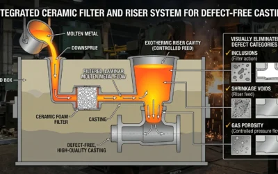
Here’s what actually matters: understanding how inclusions sabotage riser feeding efficiency — and how to stop it. That knowledge changes how you diagnose defects, design risers, and select feeding aids. This breakdown covers all of it.
What Are Inclusions in Casting — And Why Riser Feeding Is Their Favorite Target
Casting inclusions fall into four main families: oxides, sulfides, nitrides, and slag. Some form inside the melt itself — these are called indigenous inclusions — born from deoxidation reactions. Others enter from outside: slag entrainment, eroded lining material, reoxidation events. Both types cause real damage. Inside a riser, though, the destruction gets much worse.
In aluminum alloys like A356, A357, and 319, post-melting particles measure 20–60 µm on average. That range sounds small. It isn’t safe. Any particle above 50 µm average disqualifies a casting from meeting quality standards. Cross 400 µm, and the part goes straight to cosmetic scrap — no exceptions.
Here’s why risers attract them:
-
Low flow velocity inside riser channels lets particles above 20 µm settle or float without resistance
-
Density differences push non-metallic inclusions into these slow zones, away from the turbulent main pour
-
Advancing solidification fronts trap inclusions at feeder necks — contamination builds up at the exact point where clean metal must flow
The outcome is enrichment. Inclusions pile up in the one location your casting depends on most. Research links this mechanism to over 50% of post-machining inclusion scrap. These defects show up as hard spots, jagged dark shapes on X-ray, and leak paths that stay hidden until the part reaches the customer.
The physics drive inclusions straight toward casting riser feeding. That won’t change — unless you step in earlier in the process.
Mechanism #1 — How Inclusions Block Feeding Channels
Think of a drinking straw packed with sand. Liquid still enters. Nothing comes out.
That’s what inclusions do to feeding channels. Not all at once — particle by particle, until the riser becomes a sealed chamber. It loses all connection to the casting it was meant to save.
The geometry makes this almost unavoidable. Feeding channels are narrow. During solidification, dendrite arms grow inward from the channel walls. They shrink the open cross-section as they go. Inclusions arriving in that shrinking space don’t pass through — they wedge in. One particle catches. The next one catches on that. Fast enough, the effective bore drops below the threshold needed to sustain compensating flow.
The blockage mechanism runs through three compounding stages:
-
Physical lodging — particles above 20 µm hit constricted passages between dendrite arms and stop moving
-
Oxide film folding — bifilms fold and seal against channel walls, cutting liquid metal pathways faster than particle buildup alone
-
Dendrite-inclusion synergy — trapped inclusions speed up local solidification, causing dendrite arms to coarsen around the blockage and seal the channel shut
The result isn’t partial restriction. It’s a complete feeding cutoff — with a large volume of liquid metal still locked inside the riser. Unreachable. Useless.
Mechanism #2 — Inclusions Disrupt Thermal Gradient and Accelerate Premature Skin Formation
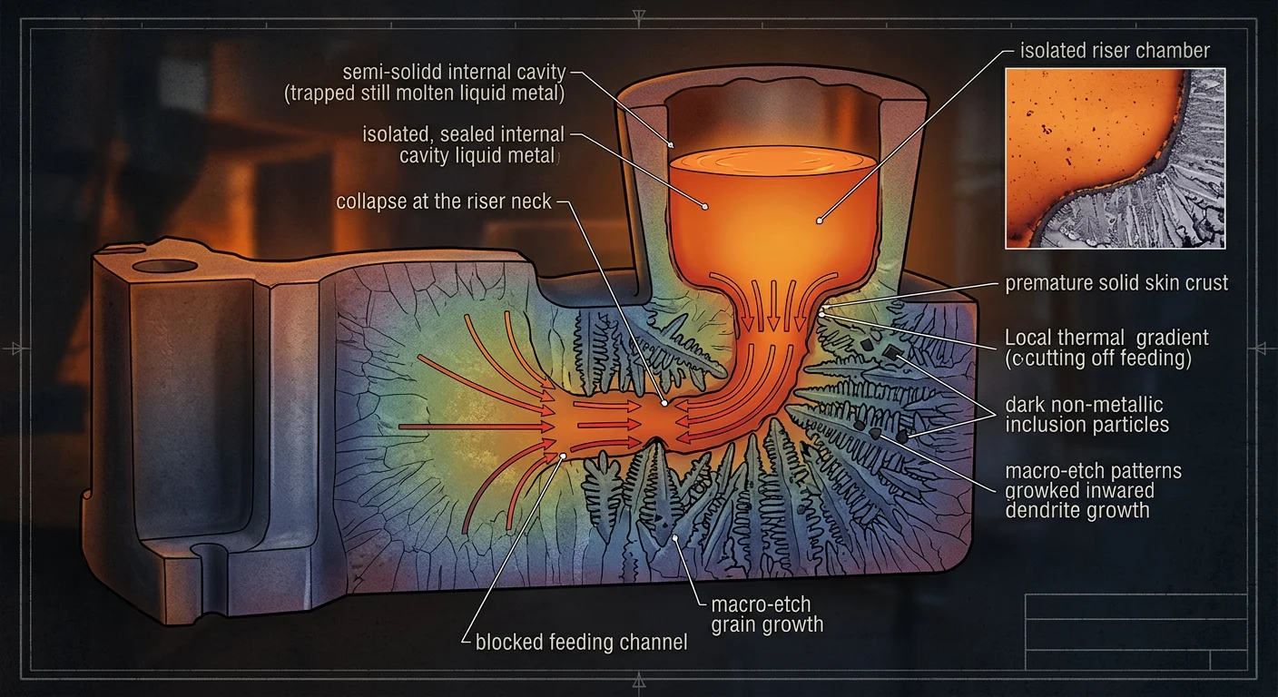
Temperature should drop in a steady, controlled path from casting to riser. That gradient is the entire feeding strategy. Inclusions destroy it.
Non-metallic particles act as thermal insulators. Their conductivity sits far below the surrounding metal. They collect at the riser neck — that’s where slow flow and solidification fronts meet. Once they gather there, they create a localized cold zone. A patch of metal that cools faster than everything around it.
That patch forms a solid skin too soon.
The damage this causes is specific and severe:
-
The riser-top surface crusts over while a large volume of liquid metal still sits underneath
-
That crust blocks atmospheric pressure compensation — the mechanism that pushes metal through the feeding channel
-
With pressure compensation gone, even a wide-open channel delivers nothing
-
The riser builds pressure from within, freezes at the surface, and becomes useless
This is what separates inclusion-driven skin formation from normal blind riser shelling. Normal shelling is controlled and follows a predictable pattern. Inclusion-accelerated shelling is erratic — it fires too soon, at the wrong spot, and seals the system before the casting draws what it needs.
The thermal gradient no longer points toward the riser. It collapses at the neck.
Shrinkage porosity follows. But by the time you see it on X-ray, the real cause — that premature insulating layer — is already gone. The inclusions absorbed into the microstructure. The evidence disappeared. The scrap rate stays unexplained.
Mechanism #3 — Inclusions from Feeding Aids Create a Hidden Contamination Loop
Most foundries never suspect their feeding aids. They’re supposed to help. That’s the cruel irony here — the tools meant to improve riser performance become the source of a contamination loop that’s nearly impossible to track down.
Here’s the problem nobody talks about: feeding aids push foreign material straight into the riser system. Exothermic sleeves, insulating boards, and covering compounds all shed particles during use. Those particles enter the melt at the worst possible moment — right when the riser is doing its most critical work.
The loop runs like this:
-
Feeding aid materials break down under heat and release non-metallic debris
-
That debris enters the slow-moving liquid metal inside the riser — the same low-velocity zone that already traps native inclusions
-
The particles drift toward the feeder neck, joining the blockage already building from mechanisms #1 and #2
-
Each feeding cycle adds another layer of contamination — invisible, cumulative, and self-reinforcing
The result keeps getting worse. The more feeding aids you use, the heavier the inclusion load grows. You fix one feeding problem and create another one in its place.
The timing is what makes this loop so dangerous. Contamination peaks at the same moment the riser needs full, unobstructed flow. By the time solidification finishes, the evidence has been absorbed into the microstructure. The scrap report flags porosity. The real cause — your feeding aid — never shows up.
How to Diagnose Inclusion-Driven Feeding Failure (Before It Costs You Scrap)
The scrap report never tells you the real story. It shows porosity. What it misses: polygonal MgO·Al₂O₃ clusters wedged into your riser neck — the ones that killed the feeding path three hours before solidification finished.
Diagnosing inclusion-driven failure means knowing where to cut, what to measure, and what the numbers are telling you.
Start with your chemistry logs — before you touch a single sample:
-
Sulfur above 0.06% puts you in danger zone. At 0.09–0.135%, sulfides precipitate during solidification. This spikes melt viscosity and traps oxides inside interdendritic feeding channels. Feeding failure follows.
-
Rare earth additions outside the 0.1–0.2% window push the oxidation inclusion load higher. That excess goes straight into the slow-flow zones.
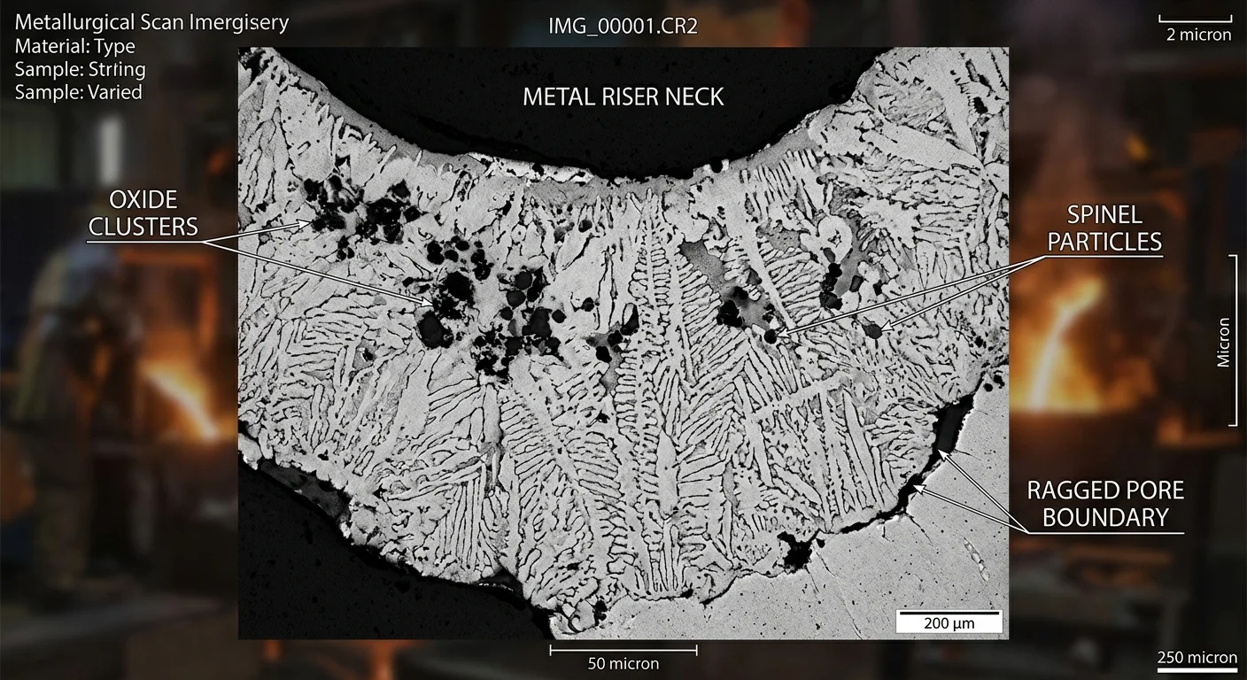
Then cross-section the riser neck. That’s your primary sample location — not the casting body. Cut Φ6 mm × 10 mm cylinders from suspected blockage zones. Polish through 800–2000 grit. Examine at 500× magnification.
Look for these three things: irregular pore boundaries, dark oxide films coating pore walls, and clustered distribution near the feeding path. Pure shrinkage looks clean — smooth walls, predictable geometry. Inclusion-driven failure looks ragged and dirty.
Pores look off? Run SEM/EDS. The dominant signature at feeding failure sites is polygonal MgO·Al₂O₃ spinel — sometimes wrapped, with MgO cores inside. That morphology pinpoints where the contamination started.
Last step: audit your pouring temperature logs. Low temperature means inclusions never floated. They went straight into your feeding channels and stayed there.
Solution #1 — Melt Cleanliness Control: Stop Inclusions Before They Reach the Riser
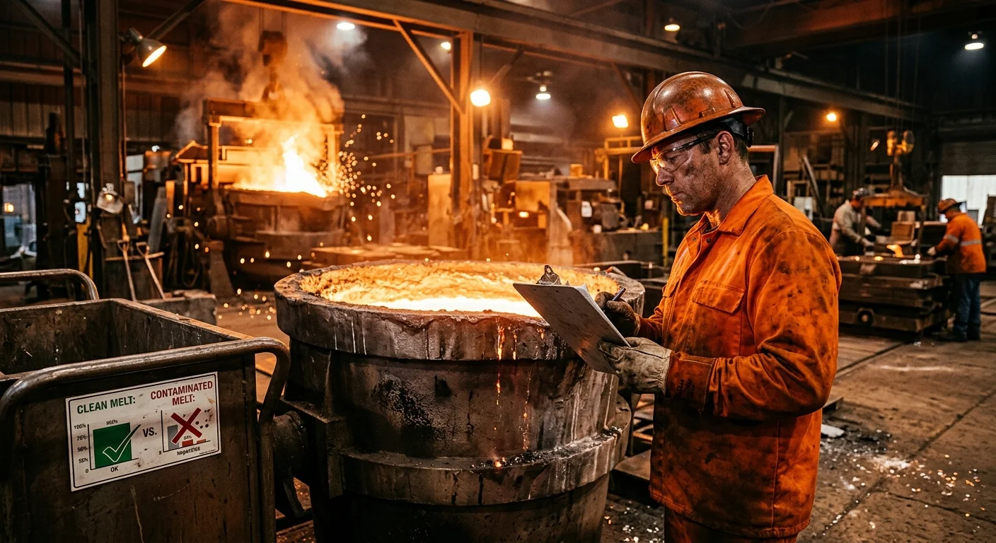
The cheapest inclusion to remove is the one that never reaches your riser. Downstream fixes — better sleeves, adjusted riser geometry, tighter pouring controls — all cost more and deliver less. Clean the melt first. That’s where you win.
Three tools do the real work here.
Rotary Degassing
A rotary degasser breaks inert gas — argon or nitrogen — into a dense cloud of small bubbles. A spinning impeller drives this process. Those bubbles do two jobs at once: they strip dissolved hydrogen and drag non-metallic inclusions to the surface.
The physics favor larger particles:
– Inclusions above 20 µm get captured with strong consistency
– Anything below 5 µm escapes with little interference
That gap matters for fine oxide films. But for the particle sizes that block feeder necks — 20 µm and above — rotary degassing is your primary weapon.
Bubble size is the critical variable. Smaller bubbles create more surface area. More surface area means more contact with the inclusion population. So push for the finest bubble generation your equipment allows.
Filtration
Foam ceramic filters and fiber tube filters target what degassing misses. In aluminum systems, ceramic foam works well against oxides and bifilm entrainment. Fiber tube filters catch finer NMIs with comparable results.
Neither one replaces degassing. Use them together and you close the gap.
Solution #2 — Riser Design Modifications That Minimize Inclusion Accumulation
Clean metal gets you halfway. A well-treated melt still carries residual inclusions. Where those particles end up depends on how your riser is shaped.
Geometry isn’t passive. It either herds inclusions away from your feeding path or concentrates them right where blockage will cost you. Three design decisions separate those two outcomes.
Tapered Necks Over Cylindrical
Cylindrical necks are traps. Tapered necks — cut at a 5–10° angle with a top-to-base diameter ratio of 1.2 or greater — reduce inclusion deposition at the neck base by 15–20%. Simulation data backs this up. The tapered geometry redirects 80% of particles above 50 µm upward into the riser body, away from the critical feed zone. Keep height-to-diameter at 2.5 or above. Size the base diameter at 80% of the top diameter. That removes around 90% of neck blockages from sub-100 µm particles.
Side Risers for Aluminum Alloys
Aluminum and silicon alloys with densities below 2.7 g/cm³ perform better with side risers than top risers. The horizontal flow path adds 30% more travel distance. That gives low-density inclusions enough time to drift toward side walls instead of piling into the neck. Inclusion capture efficiency climbs 25%. Porosity drops 18%. Yield increases 16%.
Top risers suit steel, where buoyancy velocity exceeds 0.1 m/s and vertical flotation is reliable. For aluminum, top risers collect 40% more inclusions at the neck. That’s the wrong direction.
|
Design |
Inclusion Reduction |
Yield Increase |
Porosity Decrease |
Best For |
|---|---|---|---|---|
|
Tapered Neck |
18% |
16% |
18% |
Al, Mg |
|
Side Riser |
25% |
16% |
15% |
Al/Si |
|
Williams Core + Vent |
22% |
12% |
20% |
Steel, Al |
No single modification covers everything. Stack these three, though, and the geometry starts doing the filtration work — before any inclusion reaches the point of no return.
Solution #3 — Feeding Aid Selection and Compatibility Testing to Prevent Contamination Loop
Your feeding aids are suspects. Treat them that way.
Exothermic sleeves, insulating boards, and covering compounds share one uncomfortable trait: they shed debris under heat. That debris lands inside the riser — the low-velocity zone already built to trap every particle that enters it. You’ve spent time cleaning your melt and dialing in your geometry. A bad feeding aid match wipes out both.
Aluminothermic vs. Silicothermic Agents
Reaction chemistry matters. Aluminothermic exothermic sleeves generate aluminum oxide byproducts. In Aluminum Alloy systems, that adds MgO·Al₂O₃ spinel loading — straight into the neck. Silicothermic agents run cooler. They also produce less reactive slag. For aluminum and magnesium alloys, silicothermic sleeves cut the exothermic-sourced inclusion load by a measurable margin.
Compatibility Testing Before Full Production
Never assume a feeding aid is neutral. Run a simple compatibility check:
-
Cast a test riser with the sleeve candidate in place
-
Cross-section the neck after solidification
-
Polish the section and examine it at 500× — look for foreign particles that don’t match your baseline melt chemistry
Particle shape and type change between your clean-melt control and your sleeve test? The sleeve is adding to the contamination loop.
Practical Selection Criteria
-
Match sleeve chemistry to your alloy type — not just your riser geometry
-
Reject covering compounds with organic binders. They break down and introduce carbon-based films into the melt
-
Check sleeve density ratings against your pouring temperature. Undersized exothermic reactions leave unreacted material floating above your feed path
The contamination loop closes once every input into the riser system earns its place there.
Solution #4 — Process Parameter Optimization to Suppress Inclusion Formation at the Source
Process parameters are where inclusion problems are born — and where you stop them before they reach your riser.
Clean melt treatment and smart riser geometry buy you margin. Process parameter control targets the root cause. Every inclusion that forms upstream of your riser is one more particle fighting for space in your feeder neck. That distinction matters.
Pouring Temperature
Low pouring temperature is the most common — and least-acknowledged — driver of inclusion retention. Cold metal moves at a crawl. Slow metal doesn’t float inclusions. It carries them straight into your feeding channels and locks them there.
Keep your pouring temperature high enough to give non-metallics time to rise and separate before the feeding path closes. Log your temperatures on every shift. Inconsistent temperature means inconsistent inclusion spread across your castings. Your scrap rate won’t stabilize until that changes.
Pour Path Discipline
How metal enters the mold controls how much new contamination forms on the way in.
-
Bottom-fill and counter-gravity systems cut turbulence at the fill front
-
Turbulence triggers reoxidation events — each one adds bifilm load before your riser sees a single drop of metal
-
A controlled fill rate reduces velocity spikes that fold oxide films into the stream
Rare Earth and Calcium Treatment
Small additions work here. Rare earths within the 0.1–0.2% window change inclusion morphology. Hard, angular oxides turn into rounder, less adhesive particles. They move through narrow channels without wedging at tight spots.
Push past that window and the treatment works against you. Oxidation inclusion load climbs instead of dropping. The margin is tight. Stay inside it.
Parameter discipline adds no equipment costs. It adds consistency — and that’s what keeps your previous three solutions performing the way they should.
Real-World Impact: What Inclusion Control Does to Your Yield and Rejection Rate

The numbers show up before the cause does.
Yield drops two points. Then three. The rejection log fills with porosity calls. Nobody connects them to the riser. They connect them to the riser size — and that’s where the diagnosis goes wrong and stays wrong.
Here’s what shifts when you take inclusion control seriously:
-
Rejection rates fall at the machining stage — not because you changed your tooling. The hard spinel clusters that were tearing up your cutters stopped forming inside the feed zone. That’s the real fix.
-
Yield climbs when feeding channels stay open — metal that was freezing inside the riser now reaches the casting. You get more usable output from the same pour.
-
Scrap patterns become readable — no more random porosity scatter. Defects follow predictable zones. You can adjust the process and see results.
Foundries that close this loop — clean melt, right geometry, compatible feeding aids, disciplined parameters — don’t just cut scrap. They stop chasing ghosts in the wrong part of the process.
Inclusion control doesn’t fix one defect. It fixes the explanation.
Prevention Checklist: The Inclusion-Free Riser Feeding Workflow
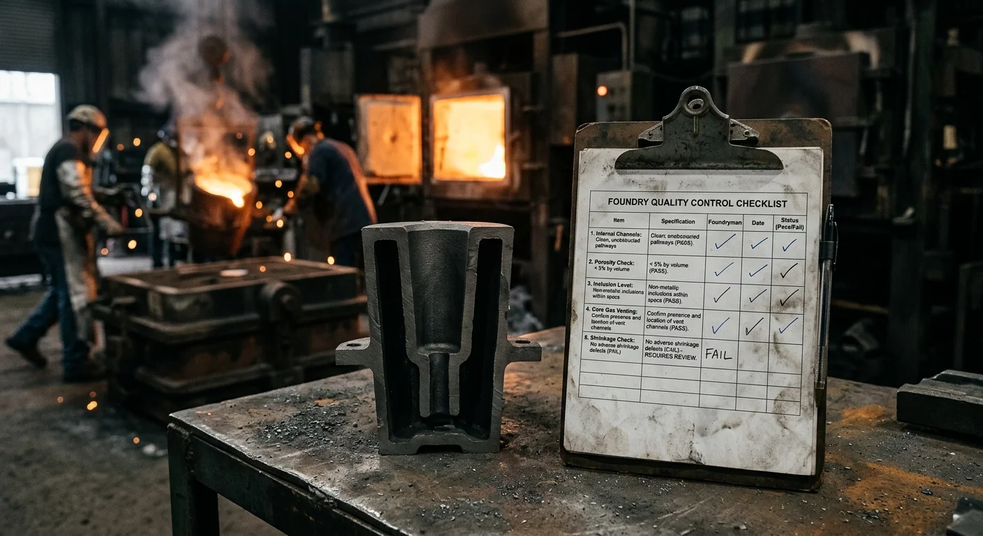
Every solution covered above is only as strong as the process holding it together. Run through this checklist at each stage — not as a formality, but as a hard verification gate. Inclusions that slip past one step will find the next one waiting.
Melting Stage
– Confirm sulfur content below 0.06% before tapping
– Log rare earth additions within the 0.1–0.2% window
– Run rotary degassing with bubble size kept small for maximum surface contact
Pouring Stage
– Keep metal transfer fall height under 12.7 mm
– Log pouring temperature at every pour — cold pours get rejected, not adjusted
– Confirm bottom-fill or counter-gravity method where reoxidation risk is high
Riser Design Confirmation
– Verify neck taper at 5–10° with top-to-base ratio at 1.2 or above
– Check Williams core modulus at 1.2–1.5× casting modulus
– Flag alloy density below 2.7 g/cm³ for automatic side-riser review
Feeding Aid Verification
– Match sleeve chemistry to the alloy — use silicothermic for aluminum and magnesium
– Remove organic binder compounds from the approved list
– Run a compatibility test on every new sleeve batch before production starts
Post-Cast Verification
– Cross-section the riser neck and examine at 500× on flagged pours
– Run SEM/EDS on irregular pore boundaries — MgO·Al₂O₃ spinel presence triggers an upstream audit
– Review rejection patterns by zone, not by total scrap count
No single gate stops everything. All of them together leave inclusions nowhere to hide.
Conclusion
Inclusions don’t fail loudly. They work in silence — blocking channels, collapsing thermal gradients, poisoning your feeding aids from the inside out. Your rejection rate starts telling a story. Your process data never saw it coming.
The fix isn’t complicated. It is deliberate.
-
Clean your melt before it reaches the riser.
-
Design risers that don’t give inclusions a place to settle and stall.
-
Vet every feeding aid you introduce. Contamination loops are almost always self-inflicted.
Do those three things with discipline. Riser feeding efficiency stops being a variable you work around. It becomes a competitive advantage you own.
The foundries winning on yield right now aren’t doing anything exotic. They stopped tolerating inclusion problems as background noise. That’s the difference.
Your next move: Run the Prevention Checklist against your current workflow. One gap is often all it takes to see why your risers aren’t feeding the way they should.