Every casting engineer has stared at a shrinkage void or a slag inclusion and asked the same question: where did the design go wrong? The answer usually comes back to the gating system — to how the runner and riser were planned, sized, and placed. Get these two elements right, and molten metal flows with control, fills the mold fully, and solidifies without issue. Get them wrong, and no downstream fix will save the part.
This guide skips the heavy theory and focuses on what matters: the design principles, sizing rules, and layout decisions that separate good castings from scrap. You’ll find everything from Chvorinov’s Rule to pressurized versus unpressurized systems — laid out in a way that’s clear and easy to apply.
What Is a Runner in Casting? Definition, Role & Position in the Gating System
The runner is the middle actor in the casting process — not the star, not the supporting role, but the one that holds the whole performance together.
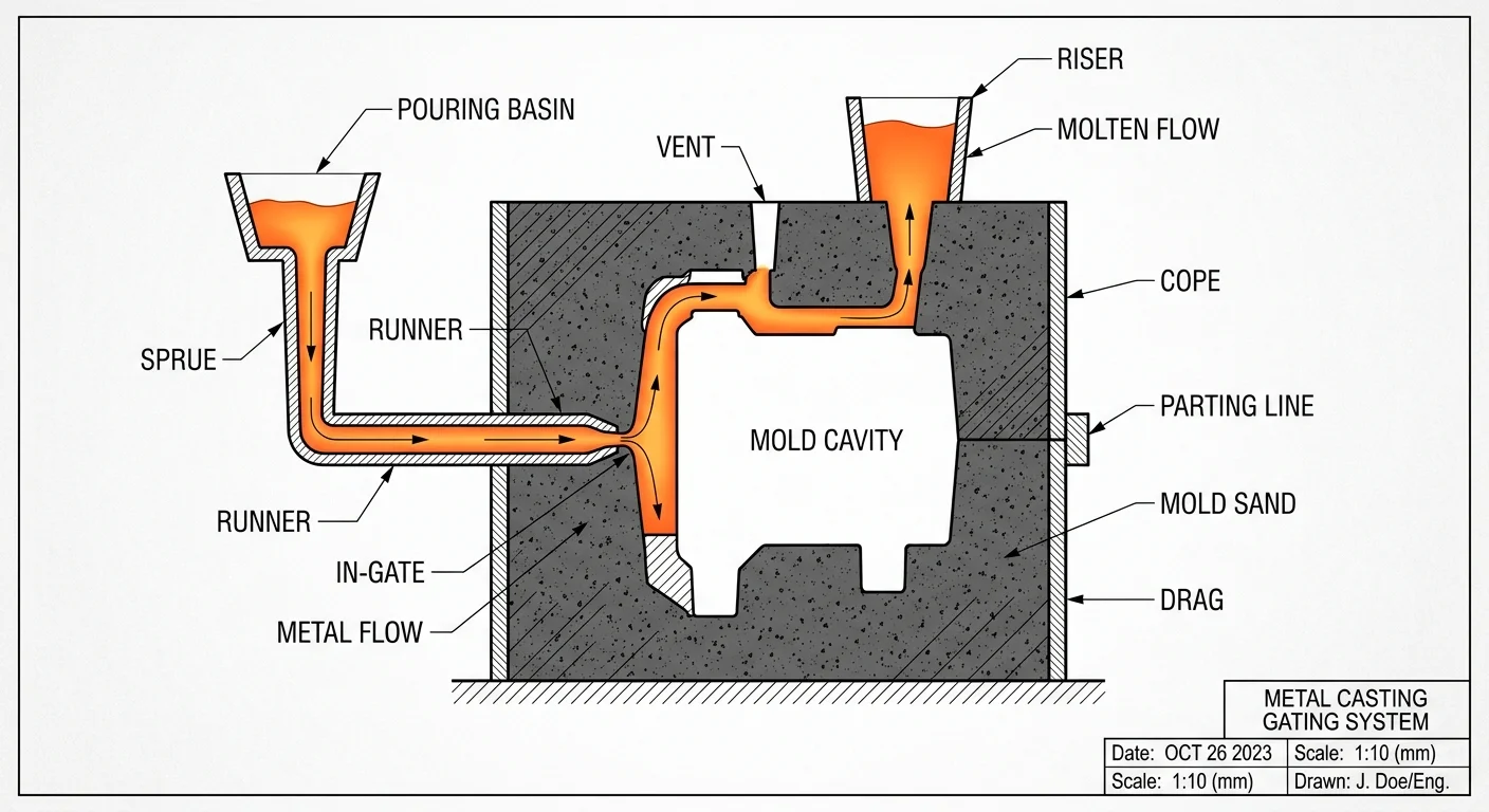
A runner is a horizontal channel. It carries molten metal from the sprue base to the in-gates. It sits at the midpoint of the metal flow path:
Pouring Basin → Sprue → Runner → In-Gate → Mold Cavity
Its job is simple: move metal evenly, keep it calm, and keep it clean.
What the Runner Does
-
Controls flow speed — reduces turbulence, mold erosion, oxidation, and gas pick-up
-
Traps slag — in-gates sit lower than the runner, so slag collects in the runner instead of entering the cavity. A short blind extension makes this work even better.
-
Feeds solidification — supplies metal as the casting cools and contracts
Geometry Rules That Matter
Keep runners short. Cut out sharp corners. At the sprue-runner junction, a 90° deflection slows the metal and drops flow rate. So the runner cross-section must widen at that point. This stops backflow from building up.
For gravity casting, use a downsprue : runner : gate ratio of 1:2:2 for standard applications. Go up to 1:4:4 for high-slag metals.
Runner area needs to be larger than the smallest downsprue area. That one sizing call protects everything further down the line.
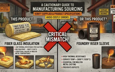
What Is a Riser in Casting? Definition, Types & Feeding Mechanism
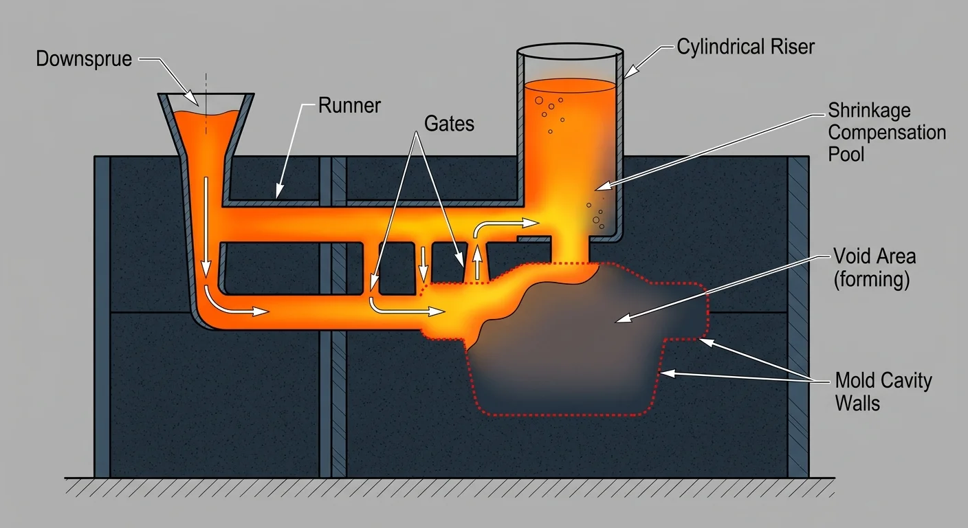
Shrinkage doesn’t announce itself. Metal cools and contracts. No fresh liquid nearby means a void forms — right at the center of the part. The riser is there to stop that from happening.
A riser sleeve is a reservoir of molten metal built into the mold. The casting solidifies and shrinks, so the riser feeds metal back in. This fills the gap before it turns into a defect. It also vents trapped gas and collects slag — useful side benefits, but shrinkage compensation is the main job.
Three Rules a Riser Must Satisfy
-
It solidifies after the section it feeds — not at the same time, not before
-
It holds enough volume to cover the full shrinkage demand
-
It keeps an uninterrupted feeding channel to the hot spot, with geometry that widens toward the riser
Get any one of these wrong, and the riser becomes decorative.
Open vs. Blind: Which Type Do You Need?
|
Open Riser |
Blind Riser |
|
|---|---|---|
|
Exposed to atmosphere? |
Yes |
No |
|
Feeding efficiency |
Lower — cools faster |
Higher — retains heat longer |
|
Best for |
Simple castings, slag venting |
Steel, complex geometries, high shrinkage |
Placement and Feeding Distance
Place risers above or beside hot spots — the thickest sections that solidify last. Multiple hot spots at different heights? Use separate risers. Also, isolate feeding zones with chills to keep each zone controlled.
Feeding distance is a radius measured from the riser center. In multi-riser layouts, those circles must overlap. Any uncovered gap becomes a shrinkage void later.
Grey iron needs small risers. The focus there is gas and slag, not heavy shrinkage. Steel shrinks hard and fast. It often needs multiple risers, especially when feeding zones push past distance limits.
Riser Aids Worth Using
-
Insulating sleeves — extend solidification time on blind risers
-
Exothermic risers — generate heat; effective on thick-section hot spots
-
Covering compounds — reduce surface cooling on open risers during feeding
-
Breaker cores — placed after feeding to support directional solidification and make knockout easier
Gating System Components Explained: How Runner and Riser Fit Together
The gating system isn’t a collection of separate parts. It’s one coordinated flow path where every component depends on the one before it.
Metal moves in sequence: Pouring Basin → Sprue → Runner → In-Gate → Mold Cavity → Riser. Each stage hands off to the next. Each stage has a defined job. The cross-sectional areas between them aren’t arbitrary — they’re the numbers that control pressure, speed, and fill quality across the entire system.
Area Ratios: The Numbers Behind the System
The areas of the sprue, runner, and in-gate (written as A_s : A_r : A_g) decide whether metal enters the cavity under control or in chaos. Here are three ratios from real production, each built for a different application:
-
2 : 1.75 : 1.5 — Engine block application. Choke sits at the sprue base. Fill is even, pour time hits 14 seconds.
-
1 : 0.9 : 0.6 — Turbine housing, compression-type system. Sprue runs Ø30 mm (706.86 mm²), runner narrows to 577.40 mm², gates total 384.8 mm².
-
1 : 2 : 1.5 — Grate bar casting. Sprue at 13.76 cm², runner opens to 27.51 cm², gate sits at 20.63 cm².
Across all three, pressure drops in the same direction: sprue > runner > gate. That step-down pattern cuts turbulence and keeps cavity filling uniform.
Where Runner and Riser Work Together
The runner feeds the cavity first — shortest path, fastest fill. The riser solidifies last. That order is by design. It creates directional solidification. Liquid metal pulls from the in-gate toward the riser as the casting cools. This keeps shrinkage concentrated in the riser, not the part.
For this to work, the riser modulus must beat the casting modulus by a clear margin. The rule: M_r ≥ 1.2–1.5 × M_c. Take a brass flange with M_c = 4.88 mm. The right riser size is M_r = 7.47 mm — a 1.53× ratio. That gap keeps the feeding channel open long enough to do its job.
Adjusting runner length to 400 mm alongside riser sizing delivers real results in production: porosity drops 18%, yield climbs 16%.
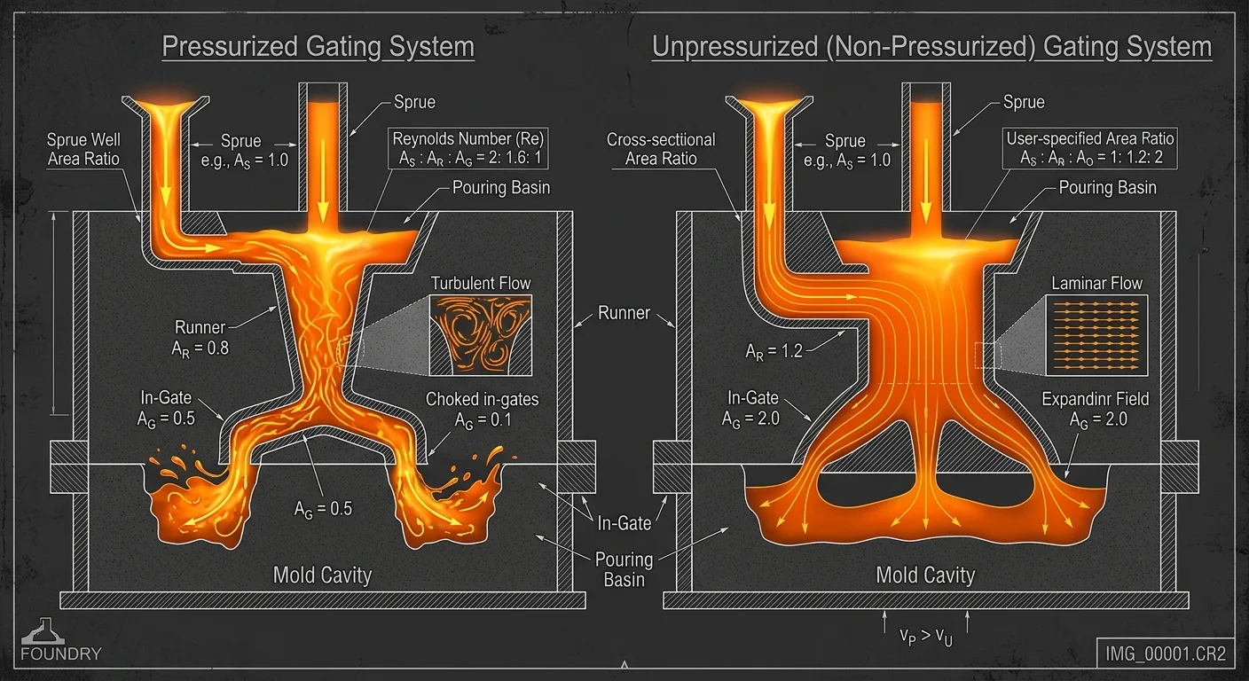
Pressurized vs Unpressurized Gating Systems: Key Differences
Picking between pressurized and unpressurized gating isn’t about preference. It’s an engineering decision with real consequences for fill quality, yield, and surface finish.
The core difference comes down to one thing: where the choke sits.
-
Pressurized system — the in-gate is the choke (smallest cross-section). Metal fills the entire runner under back-pressure, then pushes into the cavity.
-
Unpressurized system — the sprue base is the choke. Runners stay partly unfilled. Metal enters with less force and less turbulence.
Flow, Fill Time, and Yield
The pressure difference shows up clearly in the numbers:
|
Pressurized |
Unpressurized |
|
|---|---|---|
|
Fill time |
7.03–8.94 seconds |
9.35–13.06 seconds |
|
Gating ratio (As:Ar:Ag) |
1 : 2 : 1 |
~1 : 1.2–1.4 |
|
Casting yield |
Higher |
Lower |
|
Turbulence risk |
Higher |
Lower |
Pressurized systems fill faster and waste less metal. The compact 1:2:1 ratio keeps the runner and gate geometry tight. Unpressurized systems give up some yield in exchange for calmer flow. That trade matters most when turbulence would cause inclusions or oxide films.
The Naturally Pressurized (NP) Advantage
Traditional systems — pressurized or not — carry a hidden cost: entrained air. Traditional investment rigging produces over 5× more entrained air volume than a Naturally Pressurized (NP) system. That air turns into inclusions. Those inclusions turn into surface defects.
NP systems tackle this problem head-on. An offset pouring basin gives entrained air time to escape before metal reaches the sprue. Vertical in-gates trap whatever air is left. The result: fewer inclusions, better surface quality, and pour times that sit between the two traditional options — 10–11 seconds for NP setups versus 7–9 seconds for standard non-pressurized configurations.
Which System to Use
Go with pressurized for:
– Thin sections or complex geometries
– Die casting or high-pressure processes
– Jobs where yield is the top priority
– Ductile iron work on larger parts
Go with unpressurized for:
– Gravity or low-pressure casting
– Parts with thick sections and simple geometry
– Applications where metal cleanliness and laminar flow outweigh speed
– Jobs that don’t need tight flow control
One quick diagnostic: the gating ratio tells you exactly which system you’re dealing with. A ratio like 1:1.1512:2.262 (As:Ar:Ag) — where the gate area is largest — puts the choke at the sprue base. That’s unpressurized. Flip it so the gate is smallest, and you’re looking at a pressurized setup. The ratio is the fastest check you have.
Runner Design Principles: Controlling Flow, Minimizing Turbulence & Trapping Slag
Turbulence is silent. It builds inside the runner before metal reaches the cavity. By the time the casting solidifies, the damage is locked in.
The Reynolds number separates laminar from turbulent flow: Re = (L × V × ρ) / μ. Keep Re below 2000, and flow stays laminar. Cross that threshold, and metal churns. It picks up air, oxidizes, and carries slag straight into the cavity. Every runner design decision — cross-section size, length, shape, branching — either protects that number or puts it at risk.
Geometry: Where Most Problems Start
Sharp corners are the enemy. A sudden turn spikes velocity, creates backflow, and pulls in air bubbles. The fix is simple: gradual cross-section changes, smooth joints at cavity entries, and as few direction changes as possible.
Cross-section shape matters too. Rectangular runners are easy to machine and give you uniform flow. Trapezoidal runners offer better ejection and tighter flow control. Both work — but poor sizing will break either one.
Keep runners short. Each extra millimeter adds flow resistance and drops metal temperature. In multi-cavity layouts, flow rate cuts in half at each branch. Secondary and tertiary runners need to account for that split. Balanced runner systems — equal length, equal cross-section from sprue to each cavity — give you consistent temperature and flow. Unbalanced layouts save mold space, but you’ll need to compensate carefully to make up for it.
Sizing Ratios by System Type
Runner ratios are not one-size-fits-all. Match them to the system type:
-
Pressurized gating: 1 : 0.75 : 0.5 or 1 : 0.7 : 0.5 — choke sits at the gate
-
Unpressurized gating: 1 : 2 : 4 — runners stay open, flow stays calm
-
Full mold casting: 1 : 1.3 : 0.9 — tighter balance across all three zones
Pressure drop through the runner system can exceed 50–80% of total injection pressure. That’s not a rounding error — it’s the main variable driving fill quality and packing performance.
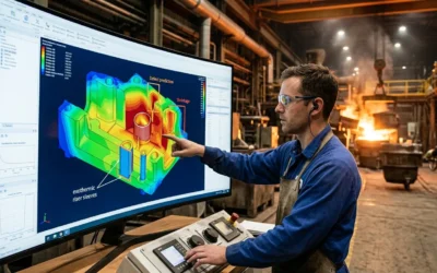
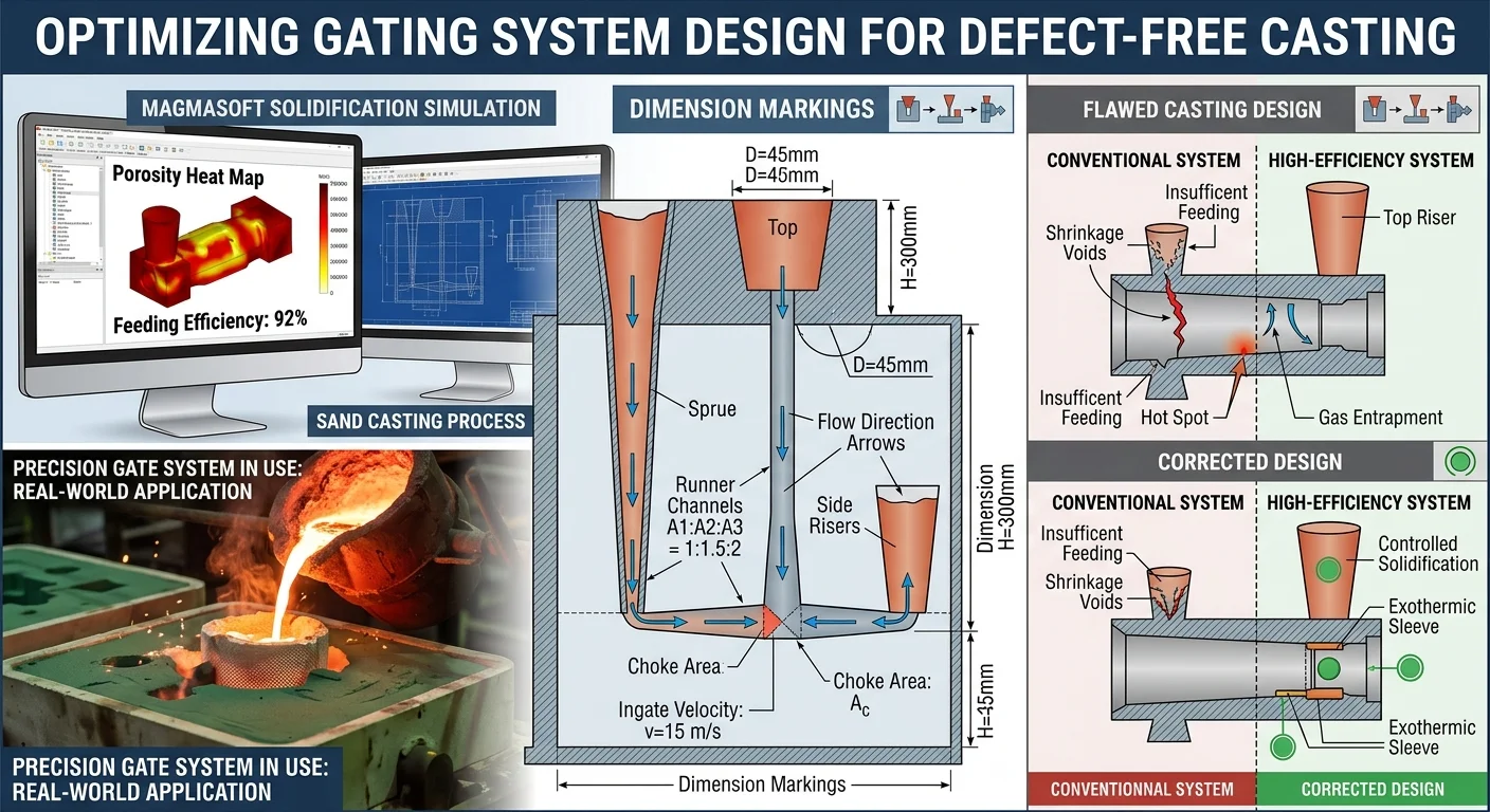
Simulation Before Steel
Never skip verification on a sizing decision. Tools like MAGMASOFT and ProCAST run the pressure drop formula — ΔP = λ × (L/D) × (ρv²/2) — across the full runner geometry. Runner Balance Analysis auto-resizes channels to reach balanced fill while staying under target pressure. It then pushes the updated dimensions into the filling study. That loop catches problems before they turn into scrapped parts.
Riser Design Principles: Chvorinov’s Rule, Sizing & Placement Strategy
Solidification time is not a guess. It’s a number — and Chvorinov’s Rule gives you the formula to find it.
t = Cm(V/A)^n
Break that down:
– t = total solidification time
– Cm = mold constant (16.0 min/cm² for cast iron; 19.5 min/in² for most other alloys)
– V/A = the solidification modulus — volume divided by surface area, measured in cm
– n = 2, in standard application
The modulus is the number that matters most. A high V/A ratio means the metal holds heat longer. A low one means it bleeds heat fast. The riser must sit on the right side of that line. No exceptions.
The 25% Rule and What It Means
The riser cannot solidify at the same time as the casting. It must solidify later — 25% longer, to be exact:
t_riser = 1.25 × t_casting
Square both moduli and the relationship holds:
(V/A)²_riser = 1.25 × (V/A)²_casting
That 25% gap is the feeding window. Close it, and the riser locks up before shrinkage compensation is done. The void forms in the casting instead of the riser. That is the outcome the riser exists to prevent.
Sizing a Cylindrical Riser: Step by Step
Spheres minimize surface area for any given volume. That makes them ideal on paper. In practice, you can’t manufacture them. The cylindrical riser is the standard — it’s the best shape you can realistically produce.
Here’s how sizing works:
-
Calculate casting volume and surface area from geometry
-
Find the V/A ratio for the casting
-
Choose a cylindrical geometry and set a height-to-diameter ratio (D = H is the standard starting point)
-
Substitute into Chvorinov’s equation and solve for D
Worked example — cast iron square plate (10 cm × 10 cm × 0.75 cm), riser required to solidify 30% longer than the casting:
-
Calculate casting V/A, apply 1.3× time multiplier
-
Set H = 1.25D, substitute into modulus equation
-
Solve for D
For a simpler case — casting volume 87.5 cm³, surface area 267.5 cm², D = H — both diameter and height resolve to 4.7 cm.
One geometry note worth knowing: a top riser sitting flush shares a surface with the casting. Subtract that shared area from both calculations. That surface loses no heat. Count it anyway, and you inflate the surface area — which gives you an undersized riser.
Placement: Hot Spots, Not Guesswork
Place risers at in-gates or hot spots — the sections thicker than their surroundings that cool last. Hot spots don’t follow a formula. They follow geometry. Metal pools where sections are thick. It holds temperature there longer. The riser needs to sit close enough to feed those zones before the channel freezes.
The feeding volume available from any riser is bounded by:
V_max = (S × V_riser) / 4
Where S is the alloy’s specific shrinkage percentage. Typical values to design against:
– Aluminum: 4–6%
– Carbon steel: 2.5–4%
– Ductile iron: 1.5–3%
Multiple hot spots? Use Caine’s method. Plot the volume ratio against the freezing ratio. This confirms riser geometry covers each zone with no overlap gaps that turn into voids.
Chvorinov’s Rule is a verification tool at its core. Run the numbers. Confirm the riser modulus beats the casting modulus. The feeding sequence takes care of itself from there.
Shrinkage Compensation by Metal Type: Designing Risers for Aluminum, Steel & Iron
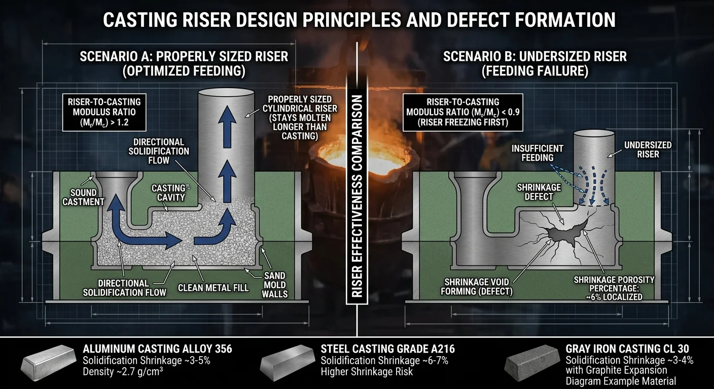
Shrinkage rates differ across metals. Riser designs that ignore this produce scrap.
The volumetric contraction numbers tell the real story:
|
Metal |
Volumetric Shrinkage |
Linear Shrinkage |
|---|---|---|
|
Aluminum alloys |
6–7% |
1.0–1.8% |
|
Carbon steel |
3–4% |
2.0–2.6% |
|
Gray cast iron |
Near zero |
0.6–1.0% |
|
Ductile iron |
— |
1.0–1.5% |
Aluminum: High Shrinkage, Short Feeding Range
Aluminum shrinks hard — up to 7% by volume. High thermal conductivity speeds up solidification. This cuts the feeding window down to just 3–5× the casting modulus. That’s about half the range you get with steel or iron.
Non-insulated risers fail in more than 50% of complex aluminum castings. The fix is insulated sleeves. They deliver three clear benefits:
-
Extend solidification time by 20–50%
-
Cut cavity defects by 30–50%
-
Push feeding efficiency out to 4–6× modulus
Add silicon to the mix — it pulls volumetric shrinkage down to 5–6%. Pair that with targeted chilling and insulated risers, and you cut scrap rates by 40%.
Steel: Consistent Shrinkage, Demanding Risering
Carbon steel shrinks at 3–4% by volume. Pattern designs need linear allowances of 2.0–2.5%. The contraction is predictable, but it leaves no margin for error. You’ll need multiple risers, especially where feeding zones reach their distance limits.
Gray Iron: The Exception
Gray iron breaks the rules. During eutectic solidification, graphite expands — up to a 10–15% volume increase. This offsets most of the 2–3% volumetric contraction. Net linear shrinkage drops to just 0.6–1.0%.
In thin sections under 50mm, you can often skip risers altogether. Heavy sections above 100mm lose that advantage. Graphite expansion becomes insufficient, and shrinkage risk returns.
White cast iron has no graphitic compensation at all. At 2.0–2.5% linear shrinkage, it behaves much like steel.
Common Casting Defects Caused by Poor Runner and Riser Design (and How to Fix Them)
Four defects cause most casting rejections linked to gating system failures. Each one has a clear mechanical cause — and a fix that works when you apply it right.
Gas Porosity
Abrupt changes in runner cross-section push metal velocity above 1.5 m/s. At that speed, spiral gas entrapment kicks in. Void volume climbs 10–20% before the casting solidifies.
Fix: Taper the runner at a 1:10 ratio. Size the cross-section to at least 4× the sprue base area. That drops velocity below 0.5 m/s and keeps flow laminar. Add skimmer traps at the runner extension — they cut porosity by 70% on their own.
Shrinkage Cavity and Porosity
A riser sized below 1.2× the modulus of the thickest section loses its open feeding path. Placement matters just as much. Move a riser from the right hot-spot to a secondary location, and shrinkage defects jump 3×.
The data is clear. One misplaced riser produces 3.18–5.01% shrinkage. Two risers placed at last-to-freeze hot spots bring that down to 0.9–2.06%. That’s a drop from a 47% defect rate to just 2.3% in T-section geometries.
Fix: Size riser volume to >1.5× the casting’s shrinkage volume (4–7% for iron). Run simulation to confirm placement — optimal positioning extends open feeding time by 20–30%.
Slag Inclusion
Flow turns sharper than 90° at velocities above 2 m/s. That pushes non-metallic inclusions — 0.5–2 mm in diameter — straight into the cavity. A poor runner design causes a 15–25% defect spike during intermittent pours.
Fix — three steps, in order:
1. Install straight-pour trap pockets (50×50 mm) at 45° bends
2. Increase runner diameter by 20% to hold velocity below 1 m/s
3. Add ceramic filters (10–30 ppi) — inclusion rates drop 80%
Sand Erosion
Sand molds have a hard velocity ceiling: 4.5 m/s. Push past it, and erosion pits form at sharp corners — 0.5–2 mm deep. Sand particles pull straight into the melt.
Fix: Size the runner area for flow below 3 m/s (a 50 mm diameter runner handles a 10 kg/s pour rate). Radius all turns to >50 mm and use a 1:100 taper. Refractory coatings cut erosion by 50%. A full redesign hitting these numbers reaches 90% defect elimination.
Step-by-Step Gating System Design Process: From Casting Geometry to Final Layout
Good gating design moves in one direction: from the part outward. Start with the geometry, work backward through the math, and end with a layout you can verify. Here’s how that process runs.
Step 1: Read the Geometry First
Wall thickness tells you where solidification starts and where it stops. Sections under 5mm freeze first. Anything over 15mm needs a feeder. Mark your hot spots before touching a calculator. Those include intersections, thick bosses above 20mm, and any abrupt section changes.
Run a quick Chvorinov’s check on those zones. Any section with a V/A ratio above 1.5 is an isolated feeding problem. Fix it in the design stage — not on the shop floor.
Step 2: Size the Gating System in Reverse
Work from ingate back to sprue — not the other way around.
-
Ingate area: Set at 0.8–1.2× the casting’s sectional area. This keeps metal velocity below 1.5 m/s.
-
Runner area: 1.1–1.5× total ingate area. Add a 1.2 branching factor wherever the runner splits.
-
Sprue area: 0.7–0.9× the runner. Taper it at a 1:100 ratio to control velocity through the choke.
For aluminum alloys, the working ratio is sprue:runner:ingate = 1:1.2:1.0. Target ingate velocity at 0.5–1 m/s. Cross 3 m/s anywhere and turbulence takes over.
Step 3: Decide Riser Count and Position
One riser or multiple comes down to three variables: modulus, mass, and hot-spot count.
|
Condition |
Single Riser |
Multiple Risers |
|---|---|---|
|
V/A > 2.5, isolated hot spot < 10% volume |
Top-mounted on thickest section |
— |
|
Mass > 5kg, more than 2 hot spots |
— |
One per 20–30% volume, spaced > 2× section thickness |
|
Shrinkage-critical alloys (Al: 4–6%) |
Top or side if accessible |
Parallel ingates to feeders |
Attach risers to sections thicker than 12mm. Keep draft angles above 5° so removal doesn’t damage the casting.
Step 4: Close the Loop With Simulation and Trial
Paper design gets you close. Simulation locks it in.
Run MAGMASOFT or an equivalent tool. Check that fill time stays under 10 seconds. Solid fraction at hot spots should stay below 20%. Shrinkage over 2%? Increase ingate area by 10–20% or add a riser. Re-run until defect risk drops below 5%.
Pour 3–5 trial castings. Inspect by X-ray or ultrasonic testing. Targets: porosity below 1%, shrinkage below 0.5%.
Results come back short? The fixes are direct:
– Fill defects → enlarge runners by 15%
– Porosity → push riser modulus 20% above casting modulus
– Cold shuts → add ingates, reduce individual gate size by 10% to balance flow rate
The benchmark for a finished design: yield above 90%, scrap below 5% after iteration. Anything short of that means one more pass through the loop.
Conclusion
Shrinkage voids, misruns, turbulent pours — they all trace back to the same root cause. A gating system that wasn’t properly designed.
The runner controls how metal enters. The riser controls what happens after. Get both right, and you’re doing more than filling a mold. You’re creating a controlled, directional solidification process that gives defects nowhere to form.
The principles covered here — Chvorinov’s Rule, pressurized vs. unpressurized flow, slag trapping geometry, shrinkage compensation by metal type — are not just theory. They’re practical tools. A casting that clears inspection on the first pull vs. one that burns three reruns and damages a customer relationship — that gap comes down to these decisions.
So take what you’ve learned and apply it. Audit your current gating layout right now. Check for overlooked runner tapers. Look for undersized risers. Any one of those gaps could be cutting into your yield today.
Design with intention. Pour with confidence.