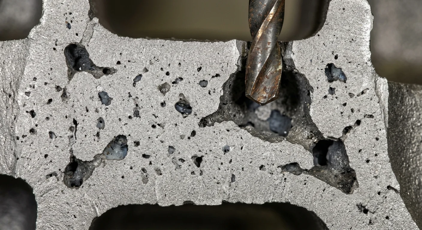
Shrinkage defects in Ductile Iron have killed more promising castings than almost any other failure mode. The frustrating part? They often don’t show up until you’re deep into machining.
One moment, a part passes visual inspection. The next, you’re staring at a voided crankshaft and explaining the scrap rate to your production manager.
Knowing why shrinkage defects in ductile iron happen is half the battle. The real leverage comes from knowing which variables to pull — and at what point in the process.
What Are Shrinkage Defects in Ductile Iron? (Types & Visual Identification)
Three distinct defect types. Each one hides in a different place. Each one causes different damage.
Getting the taxonomy right matters. Label a shrinkage cavity as porosity, and your corrective action goes in the wrong direction.
The Three Types
Shrinkage Cavities (Macroshrinkage)
These are the large ones. Smooth walls, often funnel-shaped at the surface. Form internally, and the walls turn dendritic and irregular. Size exceeds 1mm. Isolated liquid pools during the early solidification stage cause them — a feeder neck that’s too small, or a pour temperature running too hot.
Shrinkage Porosity (Secondary Shrinkage)
Smaller voids. Jagged, angular edges with dendritic internal surfaces. Macro porosity (>0.5mm) shows up as linear marks under inspection. Micro porosity (<0.5mm) needs a microscope to spot — spongy, interconnected networks scattered through the wall section.
Microshrinkage Porosity
The hardest type to catch. It spreads along eutectic boundaries and interdendritic axes. Angular, near-invisible to the naked eye. You need microscopy to confirm it — and inspectors often misread it as normal grain structure variation.
Where They Form
|
Defect Type |
Typical Location |
|---|---|
|
Surface cavities |
gating systems, feeder tops |
|
Internal cavities/porosity |
Hot spots, thick sections, riser roots |
|
Microshrinkage |
Eutectic boundaries, casting centerline |
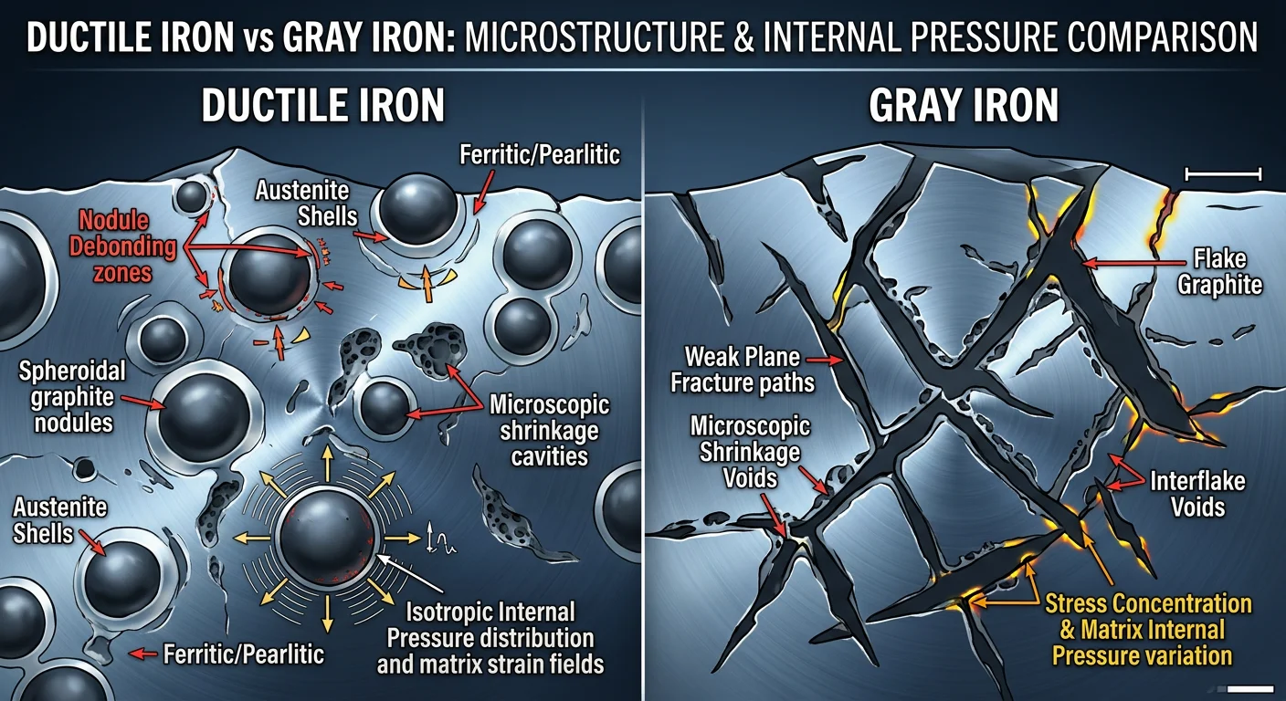
One number frames the stakes: ductile iron develops shrinkage defects 3–4× more often than Gray Iron. It gets less graphite expansion compensation. Plus, nodule formation adds more internal pressure. The margin for error is razor thin.
Why Ductile Iron Is So Vulnerable to Shrinkage (The Metallurgical Root Cause)
Three metallurgical strikes. Ductile iron carries all three — and they make each other worse.
The shrinkage problem starts at the graphite level. In gray iron, flake graphite expands outward during solidification. It compensates for volumetric loss on its own. Clean, effective, forgiving. Ductile iron’s spheroidal graphite works differently. It grows fast, gets sealed inside an austenite shell, and generates an expansion force 5× greater than gray iron — but that force stays trapped. It doesn’t reach the surrounding liquid. It doesn’t feed the shrinking mass. It just pushes against the mold wall. The wall flexes even a little, and you’ve grown the cavity instead of closing it.
Then there’s the eutectic solidification window. Ductile iron’s eutectic stage runs more than twice as long as gray iron’s. That extended mushy zone — where solid and liquid coexist across a wide temperature range — keeps the metal in a state where feeding is physically blocked. Liquid metal between austenite dendrites can’t move. It shrinks in place.
The spheroidizing treatment adds a third layer of trouble. Here’s what magnesium and rare earth additions do:
-
They reduce dissolved gases and active nuclei
-
They increase undercooling
-
They push carbide formation higher
All three suppress graphitization. All three raise shrinkage tendency.
The result: scattered micro-porosity that forms below hot spots and through the centers of thick sections. Not one clean void you can feed. Dozens of small ones you can’t.
That’s why ductile iron develops shrinkage at 3–4× the rate of gray iron. The physics are stacked against you from the first pour.
The 5 Key Factors That Trigger Shrinkage Defects in Ductile Iron Castings
Split the root causes in half and the picture gets clear. 50% of shrinkage defects in ductile iron trace back to sand systems, feeding, and gating. The other 50% come from metallurgical variables — carbon equivalent, pouring temperature, inoculation practice, and magnesium residuals. Fix one side only, and the defects keep coming.
Here are the five factors that drive the damage.
1. Temperature Gradients and Uneven Solidification
Thin sections freeze first. Thick sections stay liquid longer. That temperature gap widens. Isolated pockets of molten metal get cut off before feed metal can reach them. They shrink in place.
Directional solidification is the principle that metal should freeze in steps — from thin to thick, toward the feeder. That process breaks down under uneven temperature conditions. Wide solidification zones form. Porosity follows.
2. Spheroidizing Treatment Side Effects
Magnesium additions clean the melt. That’s the benefit. The cost? Suppressed nucleation, increased undercooling, and a harder path to graphitization.
Push Mg residuals above 0.05% and shrinkage tendency rises fast. The safe window is 0.035–0.04%. Go above that, and Mg starts acting as a carbide stabilizer. Carbides then block the graphite expansion you need to offset shrinkage.
3. Alloy Composition Imbalances
Excess manganese forms carbides. Low carbon-to-silicon ratios in thin walls tighten the shrinkage window further.
The numbers tell the story. A gray ductile iron composition running C 3.22%, Si 3.70%, Mn 0.51%, Mg 0.060% produced a 5.50% shrinkage rate — compared to gray iron’s 1.65% under similar conditions. That’s more than three times higher.
Raising carbon lowers shrinkage risk. But it creates a new problem: graphite flotation in thick sections. Every composition change trades one risk for another. There’s no free adjustment.
4. Mold Design and Gating System Failures
An undersized feeder neck starves the casting at the worst possible moment. A riser with the wrong modulus freezes before the section it needs to feed. Runner geometry changed on the shop floor — even a small change — cuts feed metal availability without anyone catching it.
These aren’t abstract design errors. They’re slow drift. They build up across shifts and surface as scrap at the machining stage.
Alloy segregation of elements like Mo and Cr adds to the problem. These elements create localized hard zones that block feeding. The result is shrinkage that no amount of riser sizing can fix after the fact.
5. Superheat and Pouring Temperature
Higher pouring temperatures increase liquid shrinkage volume. More liquid to lose means more cavity to form. At 1290°C, gray ductile iron compositions have measured 5.50% total shrinkage.
Lower the temperature and shrinkage drops — but cold lap risk goes up. The gap between too hot and too cold is narrow. It also shifts based on section thickness, alloy grade, and mold permeability. You can’t pick one number and hold it across all conditions.
EN 500-14 grade ductile iron requires risers and feeders by specification — unlike most Gray Iron castings. That requirement exists because pouring temperature alone can’t solve the compensation problem.
Control all five factors and shrinkage stays manageable. Leave even one of them unchecked, and the other four won’t save you.
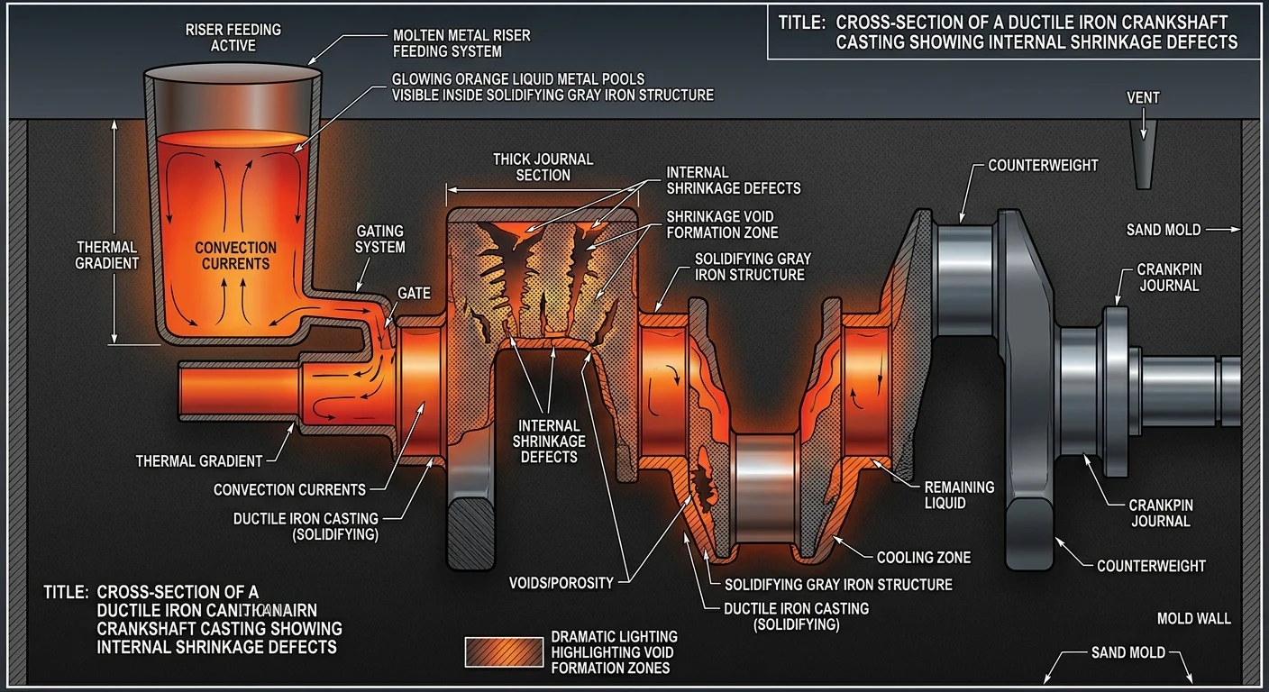
How Shrinkage Defects Form in Complex Castings: The Crankshaft Case Study
Crankshafts don’t follow the same rules as simple castings.
Take a flat plate or a uniform cylinder — shrinkage behaves in a way you can predict. You feed it, you contain it, you move on. A crankshaft is different. It gives you journals, balance blocks, sharp cross-section changes, and a shape that builds its own heat pattern — one your process engineer didn’t plan for.
The fourth main journal is where this shows up most clearly. In spheroidal graphite iron crankshaft studies, that journal forms a large, isolated molten pool that solidifies last. Everything around it freezes first. That pool shrinks on its own, with no feed metal nearby to draw from. The defect zone it creates is not random or hard to explain. Geometry causes it.
The driving force here is solidification asynchrony. Thick sections like journals cool slower than the thin sections around them. This pushes liquid contraction into one concentrated area. At the balance block–shaft neck junction, that heat buildup becomes something you can measure. Predicted defect volumes at crankshaft journals sit around 6 mm³ on average — enough to show up as shrinkage porosity during inspection.
Two defect types show up, and location separates them:
-
Macroshrinkage forms at journal locations — large open cavities that develop where solidification finishes last and volume contraction runs high
-
Microshrinkage appears in thinner connecting regions — fine, branching networks that get trapped by faster cooling
Mold material either makes this worse or pulls it back. Resin-bonded sand (thermal conductivity ~0.3 W/m·K) stretches the solidification window and raises shrinkage severity. Metal chills (~50 W/m·K) speed up cooling and cut defects — but overdo it and cold shuts become the next problem.
Composition sets the starting risk level. QT820-3 ductile iron carries a carbon equivalent near 4.4 — a range that leans toward shrinkage without strong feeding support. Run short on riser metal at that CE and you don’t just increase defect odds. You lock them in.
Directional Solidification: The Core Strategy to Prevent Shrinkage
Every shrinkage defect in ductile iron shares one thing: metal ran out of somewhere to go.
Directional solidification fixes that. The principle is straightforward — thin sections freeze first, thick sections freeze last, and feed metal flows toward the heaviest mass. Shrinkage can’t form in isolation because liquid metal is always there to replace what’s contracting.
Execution is where most foundries go wrong.
What directional solidification requires:
-
Mold layout that drives solidification from the casting’s far end toward the sprue — not at random, not in a balanced pattern
-
Wall thickness transitions that taper in steps, never jump in sudden leaps
-
Risers placed to be the last thing that freezes — sized so they stay liquid when the heaviest section contracts
-
Gating aimed straight at heavy sections, not spread out for flow convenience
Chills are the precision tool here. External and internal chills cut solidification time in targeted zones. They force the sequence you want, rather than leaving it to chance. The Niyama criterion tells you whether it’s working — push values above the threshold (optimized simulations target 21+) and you’ve built the thermal gradient needed to push porosity out of the casting and into the feeder where it belongs.
Corners, sharp section changes, and converging heat flows create hot spots. Ribbing patterns and corrugated shapes break that up. They’re not design choices for looks — they’re tools for managing heat.
Simulate first. Place chills second. Then size your risers around the solidification sequence the simulation shows — not the one you guessed at.
Feeding System Design: Risers, Exothermic Sleeves, and Gating Optimization
The feeding system is where good intentions either hold or collapse.
You can have the right alloy, the right temperature, and a solid directional solidification plan. Still pull defective parts because the riser neck was undersized by 2mm. That’s the nature of this work. The margins are real, and they don’t bend.
Riser Sizing: The Numbers That Matter
Start with neck geometry. It scales against casting section thickness T:
|
Casting Thickness T (mm) |
Neck Diameter |
Neck Length |
Modulus Ratio (Riser/Casting) |
|---|---|---|---|
|
<20 |
0.8T–1.0T |
1.5T |
>1.2 |
|
20–50 |
1.0T–1.2T |
2.0T |
>1.3 |
|
>50 |
1.2T–1.5T |
2.5T |
>1.4 |
Drop below 0.8T on neck diameter and feed metal cuts off at 70–80% solidification. Go above 1.5T and you’re burning 15–25% of your metal yield on excess riser volume. Neither failure is subtle. Both show up in your scrap rate.
For volume, the calculation is:
V_riser = (V_casting × β) ÷ (1 − β × η)
Where β = shrinkage rate (use 1.5% for ductile iron) and η = feeding efficiency. Sand risers run 0.7–0.8. Exothermic sleeves push that to 0.9–1.0. That gap is real and worth paying attention to.
Sand Risers vs. Exothermic Sleeves
Exothermic sleeves deliver 1.5–2× higher feeding efficiency than standard sand risers. The reason is heat. They hold it 20–30% longer. That keeps the riser liquid while the casting section below it contracts.
For ductile iron with shrinkage running 1.2–1.8%, that longer thermal window is not optional. It carries load.
Switch to exothermic under any of these conditions:
-
Section modulus exceeds 25mm with shrinkage above 1.2%
-
Wall thickness passes 40mm
-
Feeding distance stretches beyond 300mm
-
Multiple thermal zones exist with expansion pressure too low to compensate
The efficiency gain in those scenarios runs +25–40%. Your sand riser modulus falls short by more than 1.2×? The sleeve fixes it. A larger sand riser won’t.
Gating Placement and Flow Targets
Gate into the thickest sections first. Those are the last to freeze. Their modulus should run 20–30% above the casting average. That’s not a guideline — it’s the condition that makes sequential solidification work.
Set runner cross-section at 1.5–2× the ingate area. This keeps flow velocity above the minimum threshold. Target ingate thickness at 0.6–0.8T. Too thin and the gate freezes before the casting fills.
Filling time benchmarks: under 10 seconds for castings below 500kg. Reynolds number above 2,000 for stable, turbulence-controlled flow. Yield targets move with casting weight — 0.50 for under 500kg, 0.67 for the 500–5,000kg range, and 0.70 above that.
Production data shows 17.65% yield improvement with porosity dropping below 2%. That’s not a simulation result. That’s shop-floor output. Size the system right, place it where the thermal data points, and the numbers follow.
Alloy Composition Adjustments That Reduce Shrinkage Tendency
Chemistry is your first line of defense — and most foundries treat it like an afterthought.
Four levers matter. Carbon, silicon, trace element control, and inoculation. Pull them right and shrinkage drops by a clear, measurable amount. Pull them wrong, and no feeding system in the world bails you out.
Carbon: Match the Range to the Wall
Thin-wall castings under 20mm need C at 2.8–3.2%. That range pushes graphite to form during solidification. It offsets volumetric loss — shrinkage reduction runs 0.5–1.0%. For thick-wall sections above 50mm, push carbon up to 3.4–3.8%. But respect the ceiling. Go above 4.0% and graphite flotation becomes the new problem.
Silicon: Not One Number for All Sections
Silicon drives graphite formation. More silicon means more expansion to offset shrinkage during solidification.
-
Thick walls (>50mm): Target 2.8–3.2% Si. This offsets 1.0–1.5% shrinkage through eutectic expansion.
-
Thin walls (<20mm): Hold a floor of 2.2% Si. Drop below it and free carbides form. Feeding efficiency falls and porosity rises by 20–30%.
Control the Suppression Elements
High manganese, rare earths, and magnesium all block graphite formation. Keep them within these limits to hold shrinkage in check:
-
Mn below 0.3% — excess manganese promotes carbides and blocks the graphite expansion you’re counting on
-
RE below 0.02%
-
Mg below 0.04% — this keeps spheroidization stable without pushing into carbide-forming territory
For heavy sections above 50mm, add La at 0.01–0.03%. It cancels out residual sulfur and phosphorus effects. That one addition lifts feeding efficiency by about 15%.
Inoculation: The Multiplier Most Shops Underuse
FeSi inoculants at 0.2–0.5% raise nodule count to above 2,000/mm². A higher nodule count cuts undercooling by 10–20°C and boosts feeding efficiency by 25%. Spheroidization stays above 90%.
The result: linear shrinkage in ductile iron drops to the 1.0–1.1% range. FeSi additions also raise total graphite count by 30–50%. That translates to 15–25% lower porosity at the section level.
No single adjustment does everything. The combination does.
Process Controls During Melting and Pouring
The melt is where discipline gets built in — or gets lost. Everything downstream depends on it. Feeding, gating, composition — all of it assumes the metal reaching the mold is exactly what you expect. It isn’t always. And the defects that follow look like feeding problems. They aren’t.
Superheat is the first number to pin down. Target 100–150°C above liquidus. That puts pouring temperature in the 1,150–1,200°C range for most ductile iron grades. Push superheat past 200°C and you dissolve the magnesium nodules before the metal touches the mold. Nucleation drops. Undercooling rises. Shrinkage follows.
Section thickness shifts the target:
|
Section Thickness |
Pouring Temperature Window |
|---|---|
|
Thin (<10mm) |
1,350–1,400°C |
|
Medium (10–50mm) |
1,320–1,380°C |
|
Thick (>50mm) |
1,300–1,350°C |
Pouring rate matters just as much as temperature. Hold a steady 5–15 kg/s throughout the pour. Uneven flow builds mold temperature gradients above 50°C. That’s wide enough to create the same localized hot spots you’d get from poor riser placement. Total pour time should fall between 20–60 seconds per mold. Go faster and you lose control. Go slower and you lose temperature.
Keep volume variation inside ±10% using stopper nozzle or valve control. Pressurized furnaces targeting 80–100% uniform fill rate cut the gradient problem before it starts.
Spheroidizing treatment runs on a tight clock. Treat 5–15 minutes before the pour. Target Mg recovery at 8–12%. Go past 20 minutes and fading starts — Mg loss runs at 0.02% per minute. That drives undercooling past 30°C and shrinkage tendency climbs fast.
Monitor pour temperature with pyrometer control at ±5°C. Run SPC across the full parameter set — 60 variables, including temperature and flow rate. Set up control charts with CpK above 1.33, use subgroups of 2–10 samples per interval, and set ±3σ alerts to fire before the defect gets cast into the part.
Automation tightens the window further. You get speed control at ±5%, volume control at ±2%, and 15–20% energy savings over manual pouring. The gains aren’t just about efficiency. They’re about consistency — and consistency is what keeps shrinkage defects from becoming a pattern rather than a rare exception.
Shrinkage-Eliminating Agents and Post-Casting Remediation
Not every shrinkage problem gets solved at the design stage. Some parts arrive with defects already locked in. That’s where shrinkage-eliminating agents and post-casting correction earn their place.
Shrinkage-eliminating agents change how pores form — not by adding more feed metal. Polyether-based agents hold 36.5% of market revenue in 2025. That number reflects real performance, not marketing. These agents lower surface tension in pore solutions. This breaks up the growth pattern in defect-prone zones before voids can take hold.
Liquid agents lead with a 54.3% revenue share. The reason is simple — fast dispersion matters. The window to intervene is narrow, so speed counts.
Field trials back this up. Dropping resin content from 1% to 0.75% pushed scrap rates below baseline levels. One process adjustment. Clean, measurable results.
Post-casting correction starts with heat treatment. Shrinkage defects leave behind residual stress that weakens mechanical properties. Heat treatment tackles that directly. Simulation-validated stress relief cycles set the standard for restoring dimensional integrity after casting.
Inspection closes the loop. You need defined rejection thresholds — tied to your specific grade and section geometry. Without them, remediation decisions are just guesswork.
Quick Diagnostic Reference: Matching Defect Type to Root Cause and Fix
Pull this out when a casting comes back wrong. Match what you see to what caused it — then move.
|
Defect Type |
Where It Appears |
Root Cause |
First Fix |
|---|---|---|---|
|
Shrinkage cavity |
Journal zones, thick sections |
Isolated liquid pool, undersized feeder neck |
Increase riser modulus ratio; recheck neck diameter against section T |
|
Shrinkage porosity |
Wall interiors, riser roots |
Extended mushy zone, Mg residuals above 0.05% |
Tighten Mg to 0.035–0.04%; add exothermic sleeve |
|
Microshrinkage |
Eutectic boundaries, centerline |
Suppressed nucleation, low inoculation |
Raise FeSi to 0.2–0.5%; verify nodule count exceeds 2,000/mm² |
Not sure what defect you’re looking at? Run the 5-Whys chain. Ask why five times, one step at a time. The answer at step five is almost never where you started — and that’s the one worth acting on.
Root causes fall into three buckets:
-
Physical — wrong temperatures, undersized geometry
-
Human — process drift across shifts
-
Organizational — no SPC, no rejection thresholds
Most chronic shrinkage problems have all three running at once.
Fix the physical first. Then close the process gap that let it happen.
Conclusion
Shrinkage defects in ductile iron aren’t random. They’re predictable, traceable, and fixable.
Every crack, void, and spongy pocket scraped from a rejected casting traces back to one of five root causes:
-
Carbon equivalent imbalance
-
Poor feeding geometry
-
Thermal gradients gone wrong
-
Process inconsistency
-
Magnesium treatment missteps
Fix the root cause. You stop fighting the symptom.
The foundries that produce clean Ductile Iron castings don’t rely on luck or last-minute fixes. They plan solidification with purpose — from alloy chemistry to gating design to pouring temperature control.