Ever wondered why some metal parts get strange holes, surface marks, or break down too early? I’ve seen this happen many times. Cast metal defects are common—even when all specs look perfect. Most people mention porosity or cracks. But more problems hide below.
1. Porosity
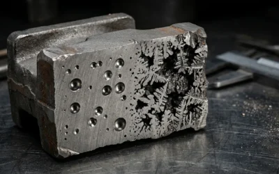
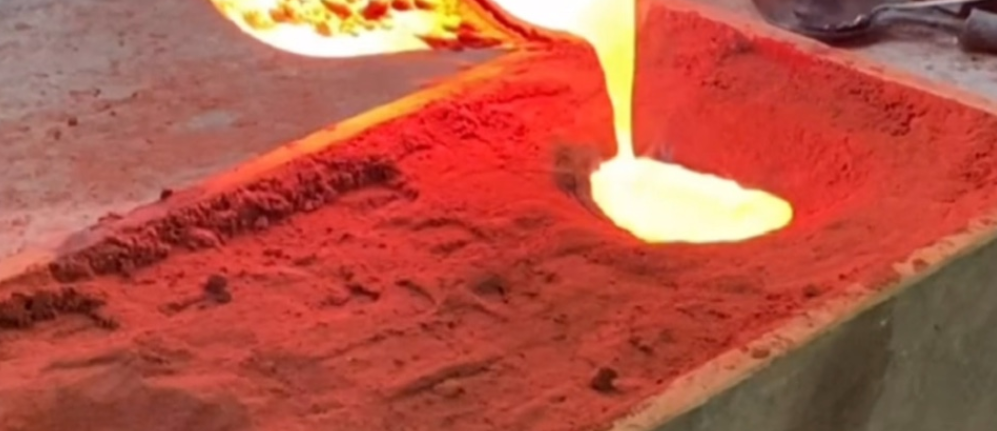
Porosity is a common defect in Metal casting. I see it most often in aluminum and magnesium die castings. It means there are voids, holes, or trapped gas pockets inside the cast metal. These weaken the part’s strength and performance.
Types of Porosity in Metal Casting
Gas Porosity: Gas porosity happens when gases (like hydrogen or nitrogen) get trapped in molten metal as it cools.
- Pinholes: Small, round holes form near the surface.
- Blowholes: Larger voids inside the part. You can’t see them without testing.
- Case Example: Moisture in smelting tools or molds reacts with molten metal. Hydrogen gas dissolves into the metal. Then bubbles form as the metal hardens. This creates visible porosity.
Shrinkage Porosity: This happens when there isn’t enough molten metal during cooling. The metal shrinks. Jagged, uneven voids form where the liquid fraction is lower.
Microporosity: Tiny voids form from fast cooling or local shrinkage. You need a microscope to see them.
Causes of Porosity
– Trapped gases come from turbulence during pouring. Poor venting or damp molds and tools also cause this.
– Not enough metal feeding or poor riser design fails to make up for shrinkage.
– Changes in pour speed, temperature, and alloy mix affect porosity.
– Poor control of mold release agents introduces extra gases.
Porosity Detection Methods
- Visual Inspection: You can see surface defects like pinholes and scars. But you won’t find major voids this way.
- Non-Destructive Testing (NDT): I recommend methods like X-ray, CT scanning, ultrasonic, or magnetic analysis. These are key for finding internal porosity.
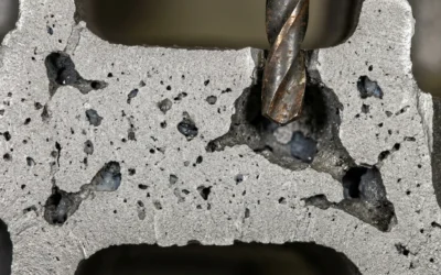
- Post-Casting Machining: Machining operations sometimes expose hidden flaws. That’s when you discover the porosity.
Impact of Porosity on Product Quality
Porosity cuts down mechanical strength and pressure tightness. Affected parts don’t work for critical uses in automotive, aerospace, and medical fields.
Surface pores lead to corrosion. They can also cause more mechanical failures.
Higher rejection rates result. Production costs go up. You need expensive rework.
Effective Ways to Prevent Porosity
Based on my experience, here’s what works:
- Proper Mold and Riser Design: Make sure venting paths are clear. Feed enough metal into the mold.
- Control of Process Parameters: Set the right temperature and pouring speed. Use clean, dry molds.
- Material Selection: I suggest using refined, low-gas alloys. Cut back on volatile mold release agents.
- Slow, Controlled Cooling: Let the metal flow and fill voids as it contracts. This reduces shrinkage porosity.
2. Shrinkage Defects
Shrinkage defects happen when metal contracts during cooling. The metal solidifies and loses volume. This creates gaps and weak spots in castings. These defects cause size problems. They also make parts weaker.
Main Causes of Shrinkage Defects
- Not enough molten metal in the mold
- Poor gating and riser systems that fail to feed metal the right way
- Bad mold design
- Wrong pouring temperature
- Uneven cooling that makes metal contract at different rates
Types of Shrinkage Defects in Metal Casting
Open Shrinkage Defects
Air fills these cavities as metal volume drops. I’ve seen these defects many times on casting surfaces:
– Pipes: Surface cavities that dig into the casting below the surface.
– Caved surfaces (sinks): Shallow, sunken spots across the surface. Air replaces missing metal here.
– Hot tears or cracks: Thin, ribbon-like splits. These form late in cooling. They appear where sharp changes or thin connections create stress.
Closed Shrinkage Defects (Shrinkage Porosity)
These form inside the casting. You can’t see them from outside: – Macroporosity: Jagged, large voids you can see with your eyes. They often appear near the core or heavy sections. – Microporosity (microshrinkage): Tiny, hidden voids around isolated liquid pools in solid metal. Impurities or dissolved gases help create these. – Improper shrinkage: This happens when metal is added at uneven rates. It often forces you to repeat the entire Casting process. – Dispersed shrinkage: A series of cavities form at right angles to a surface. – Axial shrinkage: The core of casting stays hot longer. Central voids form as edges cool faster.
Key Characteristics of Shrinkage Defects
- Jagged holes and crevices throughout the casting
- Large depressions and sunken spots in the center and thicker areas
- Thicker castings with many cross-section changes show more issues
- These defects weaken the product most of the time. Some internal shrinkage is not critical.
How to Prevent Shrinkage Defects
Based on my experience, I recommend these steps:
– Redesign cast parts. Taper thick walls. Smooth sharp corners.
– Use extra risers to ensure right filling as metal cools
– Adjust gating locations to improve metal flow
– Set up gating and riser systems for even cooling and steady feeding
– Use better alloy choices. Adjust composition if repeated issues occur.
– Improve mold design. Make sure right ventilation is present.
– Choose high-quality molding materials
– Control pouring temperature, speed, and other casting parameters with care
I’ve seen shrinkage defects cost companies a lot of money. If you don’t control them, rejection rates go up. Rework costs increase too. This is true in automotive and aerospace industries. Structural strength matters there. I suggest proper prevention methods. Thorough inspection is key to delivering reliable cast metal parts.
3. Inclusions (Slag/Sand)
Slag and sand inclusions are major non-metallic defects in metal casting. Foreign materials like sand grains, slag, or eroded furnace lining get trapped in the casting. I’ve seen how these defects lower part quality and performance.
Common Types and Visual Appearance
- Sand Inclusion: Shows up as irregular, crusty patches or embedded sand grains. You’ll often notice these next to blowholes or scabby surfaces.
- Slag Inclusion: Looks like dark-gray clusters, stringers, or thin, bite-shaped ribbons in the metal.
Causes of Slag and Sand Inclusion Defects
Sand Inclusions:
- High-speed or turbulent metal flows erode the mold. Sand or mold pieces break off and float in the melt.
- Low binder content weakens the core structure. Overbaked or poorly packed molds do the same.
- Uneven pouring rates create abrasive zones. Sharp mold corners also free sand particles.
Slag Inclusions:
- Incomplete slag removal or poor skimming during melting.
- Unclean scrap metal introduces extra oxides and impurities.
- Turbulent pouring or improper gating systems cause reoxidation.
- Furnace lining particles detach and enter the melt.
Impact on Casting Quality
Reduced Mechanical Properties: Slag and sand inclusions decrease load-bearing ability. They shorten fatigue life and structural strength.
Machining Issues: These defects often show up when machining. They cause unexpected tool wear, chips, or broken tools.
Finish Defects: Visible patches or scabs lead to cosmetic and corrosion problems.
Prevention and Remedies
For Sand Inclusions:
- Strengthen molds and cores. Optimize binder formulas and curing cycles.
- Adjust pouring speed and angle. This lowers turbulence and reduces mold erosion.
- Use mold washes. Or switch to advanced molding systems like no-bake or investment casting for better resistance.
- Redesign molds. Eliminate high-speed impact zones and sharp corners.
For Slag Inclusions:
- Use clean, well-inspected charge materials.
- Use flux or inert melting atmospheres. These reduce oxide and slag formation.
- Install ceramic foundry filters or skimmers in the gating system. They trap slag and prevent entry.
- Fine-tune gating and riser layout. Separate slag before it enters the mold.
- Pour in a controlled, steady manner. This limits agitation and reoxidation.
4. Cold Shuts
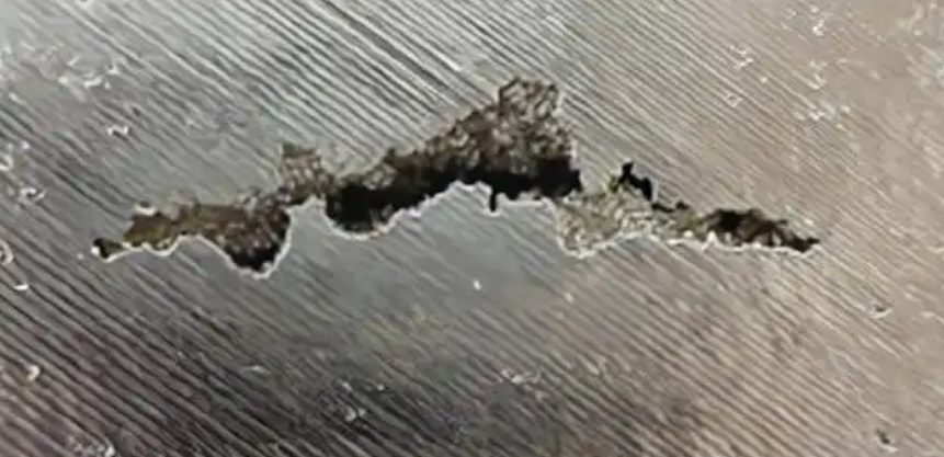
A cold shut is a casting defect. Two streams of molten metal fail to fuse together. This creates a visible, irregular, sunken line or crack between two sections. You can spot this defect by its narrow, almost straight surface mark. Often, you can see it with the naked eye. In Die casting, we call it a “cold lap point.” It appears far from the gate, and I’ve seen this happen more with aluminum alloys.
Main Causes of Cold Shuts in Metal Casting
Insufficient Fluidity of Molten Metal
- Low pouring temperatures cause molten metal to cool too fast. The metal loses its ability to fuse when streams meet.
- Incorrect alloy composition can reduce fluidity. Certain aluminum alloys flow poorly in complex or thin designs.
- Contaminants and oxides increase viscosity. This stops smooth blending.
Poor Mold and Gating Design
- Restrictive or narrow gates and runners slow the metal’s flow. The metal gets more time to cool before reaching other streams.
- Thin sections in molds act as heat sinks. Molten metal may solidify too soon. This makes cold shuts almost unavoidable.
- Poor gating systems fail to guide all metal streams. The streams don’t merge at correct temperatures and speeds.
- Poor runner layout and improper gate placements trigger this defect.
Slow Pouring and Filling
- Extended filling times let the first stream cool down. By the time the next flow arrives, it’s too late.
- In die casting, low injection speed means streams combine at lower temperatures.
Low Mold Temperatures
- A mold or die that’s too cold speeds up surface cooling of metal. In permanent mold and die casting, inadequate pre-heating is a top cold shut risk.
Unsuitable Material Composition
- High-carbon steels are more viscous. This raises cold shut likelihood.
- Alloying elements like nickel and chromium change melting points and flow. Impurities block proper fusion.
External and Environmental Factors
- Cold ambient conditions force faster cooling.
- Humidity and contamination can block metal bonding.
- Oxide layers on molten steel create barriers. Any delay between pouring steps increases cold shut chances.
Visual Characteristics & Practical Impact
- Appearance: Cracks or lines that are sunken and irregular. Sometimes they extend part of the way across the casting. Other times they go all the way across.
- Effect on Usability: Cold shuts weaken the workpiece. Parts with visible cold shuts get rejected. This is true when structural integrity matters most.
- Comparison to Misruns: Both cause weak spots. But cold shuts happen when two streams fail to join. Misruns occur when metal doesn’t reach all mold sections.
Effective Ways to Prevent Cold Shut Defects
- Keep pouring temperatures high enough for optimal metal flow.
- Pre-heat the mold evenly. Maintain mold temperature throughout.
- Design gating and runner systems that promote proper flow. Make sure metal streams merge fast.
- Adjust alloy compositions to improve melt behavior. Keep impurities low.
- Streamline processes to reduce cooling time gaps between metal pours or forgings.
Based on my experience, focus on these process controls and casting design decisions. The risk of cold shut defects will drop. You’ll see improvements in yield, mechanical strength, and product reliability.
5. Misruns
Misruns are a common casting defect. They affect part quality and yield in metal casting. This happens when molten metal does not fill the mold. You get incomplete shapes and missing sections in the final product.
What Is a Misrun in Metal Casting?
- Definition: A misrun appears when the metal freezes before it flows through the entire mold cavity. You get a casting with rounded, smooth incomplete edges. These edges show where flow stopped.
- Visual Indicators: Look for holes, shallow sections, or unfinished edges. These gaps show the metal never reached certain parts of the mold.
Common Causes of Misruns
Insufficient Molten Metal Volume: Human errors cause this. Under-pouring or misjudged open riser size means there isn’t enough metal to fill every space.
Premature Solidification: Low metal temperature causes problems. The mold may pull heat out too fast. The molten metal loses fluidity and freezes mid-way.
Ineffective Gating System Design: Bad gate or runner design fails to deliver metal fast to all mold sections. Some areas remain unfilled.
Temperature Control Problems: Bad temperature management impacts metal flow. Overheating or under-heating the melt creates issues. Inadequate heat in the mold causes premature freezing.
Industry Insights: I see misruns occur often in large, thin-walled castings. Detailed castings also face this issue. Aluminum and magnesium alloys freeze too soon if you don’t pour at correct temperatures. Based on my experience, temperature control is critical for these alloys.
Real-World Occurrence
Casting methods Affected: Misruns appear in sand casting, investment casting, and high-pressure die casting. Castings with complex shapes and rapid heat loss face higher risk.
Quality Impact: These defects increase scrap rates. I’ve seen scrap rates rise by 10% or more in bad processes. Rework and scrap costs can double. This is true for expensive alloys.
Practical Misrun Prevention Methods
Optimize Gating System: Design gates and runners so molten metal flows fast to all parts of the mold. This reduces dead zones.
Precise Temperature and Pouring Rate Control: Keep molten metal within an ideal temperature range for each alloy. Pour at controlled speeds. This minimizes solidification before the mold fills.
Maintain Flow and Reduce Turbulence: Avoid sharp direction changes in the mold system. Abrupt contractions can block flow.
Operator Training: I suggest hands-on training for foundry staff. They need to judge pouring amounts and timing well. This is key for complex or thin-walled components.
Misruns create real problems. They mean lost production time, higher costs, and rejected parts. Industries that demand flawless surface finish or precise dimensions suffer most. I recommend you tighten process control and optimize mold design. These steps keep errors to a minimum and save money.
6. Hot Tears/Hot Cracks
Hot tears, also called hot cracks, are serious defects in metal casting. They form during the solidification stage. The metal is part solid and part liquid at this point. The casting cannot contract as it cools. Poor mold design or rigid cores cause this restraint. This creates fractures that weaken the part.
Typical Signs and Key Characteristics
Hot tears can be external (you can see them) or internal (you need inspection tools like radiography or magnetic particle testing). Their jagged, crooked cracks may look like they’ve oxidized (black in iron/steel, grey in aluminum). Surface hot tears can run for several centimeters. Internal tears might be just a few millimeters. But they still have a big impact on part strength. You’ll find them at corners, edges, or where section thickness changes fast. They also appear along grain boundaries.
Causes of Hot Tears and Process Data
- Restricted shrinkage from bad mold design or inflexible cores.
- Alloy composition matters. Higher silicon or other alloying elements in aluminum increase the risk.
- Fast or uneven cooling raises defect rates. For aluminum, cooling below 1 K/s increases defects fast.
- Sharp corners or abrupt changes in section design create stress points. These trigger tears.
- Poor ejection or die misalignment can rip castings during removal from the mold.
- In some foundries, hot tears cause over 20% of all casting rejections.
Prevention Strategies and Process Adjustments
- Design molds for even cooling and free shrinkage in all directions.
- Use core and mold materials that offer some flexibility. This reduces internal stress.
- Control alloy composition. For example, limit silicon, magnesium, or copper in aluminum alloys.
- Raise mold temperature a bit to slow the cooling rate. This makes the metal more ductile during contraction.
- Don’t overheat the metal. Fill molds at controlled temperatures, not maximum ones.
- Refine die design and ejection systems. This helps avoid tearing during removal.
7. Sinks/Surface Depressions
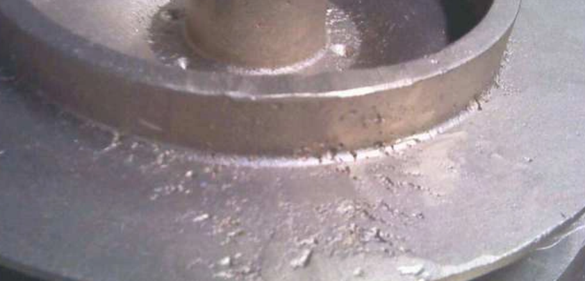
Sinks, or surface depressions, are a common defect in metal casting. I see them often in die casting for aluminum and zinc alloys. These defects look like concave dents or dimples on the surface. They are often several millimeters deep. You’ll find them opposite internal ribs, bosses, or areas where wall thickness changes suddenly.
Causes of Sinks and Surface Depressions in Die Casting
Variations in Wall Thickness: Large differences in section thickness cause uneven cooling. They also cause localized shrinkage. Thicker areas take longer to solidify. The underlying metal contracts and forms surface sinks.
Improper Mold Design: Features that don’t support uniform cooling increase the risk. Features that restrict natural shrinkage also increase the risk of surface depressions.
Overheated Die Areas: Hot spots result in slow solidification. They also result in localized shrinkage. This increases the chances of sinks forming just below the surface.
Inadequate Venting: Trapped gases create distorted surfaces. They also intensify shrinkage-related depressions.
Low Injection Pressure or Short Pressure-Holding Time: Not enough molten metal feeds into the mold during cooling. This makes shrinkage voids and sinks far more common.
Poor Cooling System Design: Inefficient cooling circuits fail to control hot zones. Cooling circuits placed in the wrong spots also fail. This allows depressions to form in critical areas.
Visible Effects and Quality Implications
- Aesthetic Concerns: Sink marks are easy to spot. They reflect light in a different way than the rest of the casting. This hurts part appearance. It may trigger expensive cosmetic rework or rejection.
- Potential for Cracks and Metal Beads: Sinks can cause stress at their edges. This leads to adjacent metal beads. It can even lead to microcracks as the last molten metal segments solidify.
- Structural Weakness: Surface depressions often indicate underlying shrinkage porosity. This can weaken key sections.
- Increased Repair and Scrap Costs: Parts with visible sinks or surface depressions may fail quality inspections. This raises production costs.
Ways to Prevent Sinks and Surface Depressions
- Design Optimization: Avoid abrupt changes in section thickness. I suggest design and die-casting teams work together from the start. Find a balance between function and uniform structure.
- Targeted Cooling Improvements: Use simulation analysis to map hot spots. Install bubblers or fountains under sink-prone areas. This improves localized cooling. It reduces the risk of surface depressions.
- Mold & Cavity Venting: Improve venting in die cavities to prevent gas entrapment. Adjust pressure-holding times and injection pressure. This maintains metal feed during solidification.
- Efficient Cooling Circuitry: Develop cooling systems that address predicted hot zones. Use advanced simulation and mold design.
- Recommended Ratios & Dimensions: Stick to wall thicknesses of 2–6 mm. Maintain a rib-to-surface area ratio close to or below 0.7 for best results.
Summary: Sinks and surface depressions are most common in aluminum and zinc die castings. You’ll find them opposite ribs and bosses. Based on my experience, prevention depends on precise design and consistent wall thickness. It also depends on advanced cooling management and close teamwork between designers and die casters. Strong mold design and cooling optimization determine success in reducing sink marks on finished metal parts.
8. Warping/Distortion
Warping or distortion is a major defect in metal casting. It causes bends, twists, or overall deformation of metal parts. This problem happens most in castings with thin walls, large flat areas, or complex shapes that aren’t symmetrical. Warping hurts product accuracy, strength, and surface finish. It often leads to more scrap or costly rework.
Incidence, Mechanisms, and Types
Frequency: Warping is a big problem in parts with wall thicknesses of 1/4 inch (6.4 mm) or less. Thinner sections are 2–3× more prone to distortion than thicker ones.
Key causes:
- Uneven cooling: Different cooling rates between sections cause internal stresses. This leads to bends and twists.
- Residual stress: Stresses from forming, cold working, or welding build up. This happens more in designs with sharp corners, small fillets, or holes.
- Imbalanced geometry: Asymmetrical parts or too many perforations create tension imbalances during shrinkage.
- Mold mistakes: Misaligned cavities and poor cooling channel layout create hot and cold zones. This triggers warping.
How to Prevent Warping/Distortion in Metal Casting
- Material choice and thickness optimization: I recommend choosing thicker or higher-strength metals where possible. This resists warping. Keep thickness variation under ±10%.
- Uniform mold and die design: Use aligned cavities. Design cooling channels to spread heat evenly. Preheat molds to reduce steep temperature gradients.
- Design for symmetry: Avoid too many perforations or asymmetric layouts. Balance supports within the geometry.
- Controlled welding and fabrication: Use symmetrical welding, short weld lengths, and staged weld sequences. This distributes heat evenly. On thin metals (<1/8 in or 3.2 mm), keep welds spaced close but balanced.
- Careful handling: Support large panels to prevent sagging or bending. Do this during transport, stacking, or processing.
- Simulation and continuous QC: I suggest using casting simulation software. It forecasts warping-prone zones. Install regular dimensional checks after cooling.
Table: Causes and Prevention of Warping
| Cause | Affected Part | Prevention Practice |
|---|---|---|
| Uneven cooling/hot spots | Aluminum engine covers | Cooling channel optimization, preheating |
| Welding residual stress | Sheet metal panels | Symmetrical welds, short weld passes |
| Thin walls, over-perforation | Steel screens | Maintain wall thickness, limit holes |
| Poor geometry balance | Cast frames (large) | Design for symmetry, balanced structure |
Key Mitigation Actions
- Match material and thickness to the use case.
- Make sure wall thickness is uniform. Use gradual transitions.
- Run multi-disciplinary reviews (designer/fabricator/molder) at the start.
- Use gradual or controlled cooling.
- Monitor internal stresses. Relieve them with the right post-processing.
- Use simulation to detect risks at the start.
9. Mold Erosion and Drops in Metal Casting
Mold erosion and drops are two common surface defects in metal casting. They cause quality and appearance problems in finished metal parts.
What Is Mold Erosion in Casting?
Mold erosion happens when the mold material wears away. This occurs as molten metal rushes through the mold cavity. Sand is the most common material that wears away. This defect is most common in Sand casting. Sand molds have lower strength compared to permanent molds.
Key Features and Causes of Mold Erosion:
– Castings show rough surfaces. Sometimes extra material sticks out.
– Erosion often results from pouring metal too fast. Weak sand also causes this problem.
– Sand grains can break free or shift position. This leads to sand inclusions inside the finished casting.
Typical Mold Erosion Defect Indicators:
– Rough or irregular spots on the casting surface.
– Extra sand particles visible in or on the metal.
– In severe cases, you’ll see widespread surface roughness. You may also see severe size changes.
Why Mold Erosion Happens:
– Too much pouring speed. Fast-moving molten metal erodes mold surfaces.
– Low strength molding sand. Weak molds can’t resist the flow. The surface breaks away.
– Poor mold design. Sharp turns or narrow runners increase turbulence. This makes erosion worse.
How to Prevent Mold Erosion:
– Lower the pouring speed. I recommend using larger runners or adding multiple gates to the gating system.
– Choose mold materials with higher strength and stability.
– Refine mold design to reduce turbulence. This helps streamline metal flow.
Drops in Metal Casting: Causes and Identification
Drops are defects where parts of the cope fall into molten metal during pouring. The cope is the top part of the sand mold. Weak or poorly rammed sand molds face this problem most.
Key Characteristics of Drops:
– Look for irregular bumps or protrusions. You’ll find them on the top surface of castings.
– Sometimes drops combine with sand inclusions. This creates mixed defects.
Common Causes of Drop Defects:
– Weak sand mix or insufficient binder in the mold material.
– Poor ramming. If the mold isn’t compacted well, particles drop off.
– Pouring at too-high temperatures can weaken the sand. This dislodges particles.
Prevention Strategies for Drops:
– Use stronger sand mixtures. I suggest optimal binder content for better mold integrity.
– Ensure correct, thorough ramming and mold preparation.
– Avoid too-high pouring temperatures.
Impact and Remedies for Mold Erosion and Drops
Both defects result in surface irregularities. They compromise appearance. They also increase the likelihood of internal inclusion defects. Mold erosion and drops can lead to expensive repairs. Rework is common. In some cases, you’ll need to scrap parts completely.
To reduce risk, review gating system design. Control pouring speed. Ensure proper mold preparation before every casting run. Based on my experience, this makes a big difference.
10. Metal Penetration and Veining in Metal Casting
Metal penetration and veining are defects that happen on the surface and inside castings. They occur when molten metal flows into cracks or gaps in the sand mold or core. This creates thin veins, fins, or rough projections on the surface. These defects lower casting quality and performance. I find them critical in complex castings or internal passageways.
How Metal Penetration and Veining Occur
- Molten metal pours into the sand mold or core.
- The high temperature heats the silica sand fast. This causes a phase change (alpha to beta) between 575°C and 599°C.
- This sudden thermal expansion cracks the sand. It opens voids.
- Liquid metal flows into these new cracks.
- The metal cools. Thin veins or projections remain. You can often see them as right-angled fins or wrinkles.
Where Veining and Penetration Happen
Typical Alloys: You see this most in ferrous metals (cast iron, steel) and copper-based alloys. But it can happen with any casting alloy.
Critical Locations:
- Water jackets in engine blocks: Internal veins become permanent flow restrictions. You cannot remove these. They cause poor performance.
- Cylinder heads and manifolds: Internal veining blocks passages. This leads to leaks and weaker structure.
- Gray and ductile iron castings: Sharp corners or large core areas invite these defects. Removal takes a lot of labor.
Quality Impact and Associated Issues
- Increased finishing costs: Removing veining from internal passages takes a lot of manual labor. You need expensive tools.
- Surface finish problems: Veining often comes with rough surfaces, burn-on, burn-in, and non-metallic inclusions. Silica grains loosen during expansion. They embed in the final casting.
- Reduced component performance: Internal veins restrict flow. They thicken walls in uneven ways. They create flow restrictions. I see this as serious in water-cooled or fluid flow components.
Examples:
- Engine block water jackets with internal fins cause flow issues and local overheating.
- Gray iron manifold with large external fins needs hand grinding. This adds to production costs.
Prevention and Control of Metal Penetration & Veining
Sand and Core Additives: I recommend specialized core additives (e.g., Veinseal). They modify sand’s thermal properties. They reduce abrupt expansion. They work well in high-temperature zones. Substitute silica with refractory sands (zircon, chromite) where you can. Or blend with flux or organic agents. These boost high-temperature core integrity.
Core and Mold Coatings: Use protective coatings. They slow down sand contact with metal. They reduce metal penetration. They prevent burn-on and burn-in.
Improved Core and Mold Preparation: Make sure you do proper ramming and compaction. Sand that is not compacted well cracks more. Metal penetrates it easier. Design molds and cores to avoid stressed or under-compacted regions. Control mold and core temperature as much as you can.
Process Parameter Controls: Monitor mold temperatures. Try to stay below the abrupt expansion threshold of silica sand. Adjust gating and riser designs. This minimizes localized overheating.
Summary
I’ve spent years in the foundry industry. I’ve learned one truth: preventing casting defects is about discipline, not luck. Each defect teaches us something. Poor temperature control leaves marks. Rushed mold prep causes issues. Ignoring design flaws creates problems. The good news? Most problems are easy to avoid. I suggest you focus on process control. Invest in proper training. Never skip quality checks. Your castings will improve. Your profit will grow too.