A cracked filter mid-pour. Molten metal bypassing the filtration zone. Inclusions showing up in finished castings you swore were clean. Sound familiar? The problem isn’t your filter — it’s where and how it was placed.
The 5 most common mistakes in ceramic foam filter placement show up the same way across foundries of all sizes. Small shops, large operations — the pattern repeats. And each mistake carries a real cost: higher scrap rates, more rework, lost pours.
Every mistake on this list has a fix. Not a vague suggestion — a specific, actionable step you can apply. You’ll find all 5 here, plus a placement checklist built to make filter failures the exception rather than the norm.
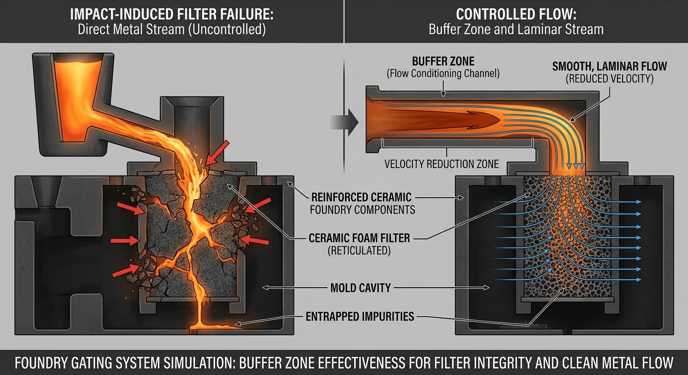
Mistake #1: Placing the Filter Directly in the Impact Zone of the Molten Metal Stream
Molten metal hits hard. Faster than you expect. With more force than most filters are built to absorb.
A ceramic foam filter placed right where the metal first strikes takes the full kinetic energy of that pour. Ceramic foam, for all its filtration ability, is not a shock absorber. It’s a rigid, porous structure built to capture inclusions. Not to take a hit.
The result? Fractures. Cracks. Sometimes complete filter collapse mid-pour.
Once the filter cracks, you don’t just lose filtration — you lose control of where the metal goes. Fragments can enter the mold cavity. The metal finds the path of least resistance, which is now the crack, not the filter face. Everything past that point is compromised.
Why This Placement Mistake Happens
The root cause is gating system design. Filters end up too close to the sprue exit, or placed beneath a high-velocity pour point. The thinking is that putting the filter earlier in the flow path gives it more time to work. That logic isn’t wrong. The execution is.
The filter needs to see the metal. It doesn’t need to take the first punch.
High-velocity metal streams hit with both thermal shock and mechanical force — at the same time. Ceramic foam can handle heat. It’s built for that. What it can’t handle is a sudden, concentrated load hitting one spot on its face before the flow has any chance to spread out.
The Fix
Reposition the filter so there’s a buffer zone between the metal entry point and the filter face. You can do this by:
-
Extending the runner before the filter seat — this gives turbulent flow time to calm down
-
Adding a well or basin upstream of the filter to break the stream’s direct impact energy
-
Angling the gating geometry so metal reaches the filter face at lower speed and spreads across a wider area
The filter should receive metal — not intercept it at full force. That one distinction separates a clean pour from a cracked filter and a scrapped casting.
Mistake #2: Skipping or Uneven Preheating Before Contact with Molten Metal
Temperature isn’t a detail. It’s the difference between a filter that performs and one that shatters on first contact.
Ceramic foam Filters are built to handle extreme heat — but on their terms, not yours. A cold or unevenly heated filter hits molten metal and the thermal shock is immediate. The material can’t expand fast enough. Micro-cracks form. Sometimes the whole filter fractures before the pour is even halfway done.
Most foundries don’t like to admit this mistake happens often — because preheating feels like an extra step. It isn’t. It’s part of the process.
What Skipping Preheating Does
A room-temperature filter meets metal at casting temperature. That gap creates a thermal gradient the ceramic can’t close fast enough. The outer surface heats up fast. The core stays cold. That mismatch builds internal stress — and stressed ceramic cracks.
The damage shows up in real ways:
-
Cold starts — metal begins to solidify before filtration can happen
-
Incomplete penetration through the filter’s pore structure
-
Gas porosity in finished castings from trapped air that proper preheating would have pushed out
-
Thermal shock fractures that can drop ceramic fragments into the mold cavity
Uneven preheating creates its own problems. One side of the filter reaches operating temperature. The other side doesn’t. Metal flows toward the hotter zone and skips the rest. Your filtration ends up partial at best.
The Right Way to Preheat
For most applications, the target range is 120°C to 150°C. That’s enough to bring the filter to a stable temperature without pushing into ranges that weaken its structure.
Here’s what proper preheating looks like in practice:
-
Measure the filter’s base temperature before placement — don’t assume it’s at room temperature
-
Heat from all sides, not just one
-
Hold that temperature through the placement process — a filter that preheats and then sits and cools is a wasted step
-
Don’t go above 150°C — you risk weakening the filter structure before it ever contacts metal
One more thing worth knowing: preheating also primes the flow path. A warm filter cuts turbulence at first contact. That means smoother metal movement and less trapped gas in the mold. That’s not a bonus — it’s a core reason the step exists.
Mistake #3: Poor Fit, Incorrect Sizing, or Inadequate Sealing in the Filter Seat
Here’s the thing about a filter that doesn’t fit right: it looks like it’s working. The metal flows. The pour finishes. You don’t see the problem until the casting comes out wrong — and by then, you’ve already lost it.
A filter sitting loose in its seat isn’t filtering. It’s just occupying space. Molten metal travels around it, through the gaps. It bypasses the one thing you installed to catch inclusions. Every gap between filter and frame is an open lane for contaminated metal.
Two Dimensions. Both Matter.
Every ceramic foam filter carries two size references:
-
Nominal size — what’s printed on the label, representing the surface area
-
Actual size — the true physical length and width of the filter body
These numbers are not always the same. A half-inch discrepancy between your filter’s actual size and your filter seat can open a gap large enough to let unfiltered metal through. That’s not a tolerance issue. That’s a filtration failure dressed up as a sizing oversight.
Measure the filter seat — length, width, and depth — with a ruler before you order. Write those measurements down. Refer to them every time.
What a Poor Fit Does to Your Pour
A filter that doesn’t seat flush causes three distinct problems:
-
Metal bypass — unfiltered metal finds the gap and takes it. Inclusions travel straight into the mold cavity
-
Structural failure — forcing an oversized filter into the seat tears and cracks the filter media. This happens before the pour even starts
-
Airflow and fill disruption — a loose filter shifts under metal pressure. The flow path changes mid-pour in ways your Gating System can’t handle
The Standard for a Correct Fit
The filter should slide in and sit flush against the frame on all sides. No forcing. No shimming. No gaps you’re hoping won’t matter.
Pressure to install means it’s the wrong size. Movement after placement means the seat geometry needs correction. Visible daylight between filter edge and frame means that gap will cost you a casting.
Check dimensions before purchasing. Verify both nominal and actual sizes match your seat. Get this step right before metal ever enters the system.
Mistake #4: Excessive Sprue Height Creating Dangerous Hydraulic Pressure Head
The physics here are unforgiving. Every extra millimeter of sprue height adds pressure at the base — and that pressure goes somewhere. Straight into your filter. Straight into your mold.
Here’s the equation that matters: P = ρgh. Density × gravity × sprue height. For aluminum, a 300mm sprue generates around 7,060 Pa at the base. Double the sprue height to 600mm and that pressure doubles too. Your gating system’s filter wasn’t built to absorb that kind of load over and over. And it will fail.
What Excessive Pressure Head Does to Your Cast
High pressure head drives metal velocity up fast. A 400mm sprue pushes metal through at around 2.8 m/s. Push it to 800mm and you’re at close to 4 m/s. That’s a 41% velocity increase — and aluminum’s turbulence threshold sits at 0.5 m/s.
Past that threshold, you’re not casting. You’re producing defects:
-
Bifilm entrainment — oxide films fold back into the melt and never leave
-
Aspiration — undersized or straight-walled sprues create sub-atmospheric pressure zones. These pull gas and contaminants into the stream
-
Jetting — high-velocity metal hits mold walls, splashes, and re-oxidizes. Fill gets compromised before the cavity reaches 20% full
-
Sand erosion — excess pressure scours runner walls. Sand inclusions enter the flow downstream
-
Back-wave formation — metal rebounds off the sprue base and travels back up. Air gets pulled back into the stream
The Fix Starts With the Sprue Geometry
A straight cylindrical sprue is the single most common source of this problem. Taper is not optional. The cross-section must shrink from top to bottom — sized to match the accelerating metal velocity and keep full-bore flow all the way through.
The formula: A_bottom = A_top × √(h_top/h_bottom)
Beyond taper, these steps bring pressure head under control:
-
Minimize sprue height to the lowest your mold geometry allows. Shorter sprues show a clear drop in air entrapment based on controlled simulation data
-
Add a sprue base well to absorb kinetic energy before metal enters the runner system
-
Position the ceramic foam filter at the sprue-runner junction to cut residual pressure and catch the inclusions that high-velocity flow drags in
-
Run flow simulation — check gate velocity against your alloy’s limit before cutting tooling, not after your first scrapped pour
The filter can handle a lot. Excessive hydraulic pressure head isn’t one of them.
Mistake #5: Lateral Stream Impact and Insufficient Support Causing Filter Tilt or Capsize
A tilted filter is a failed filter. Not eventually — right away.
Molten metal hitting a ceramic foam filter from the side creates a problem. The force doesn’t spread across the face. It concentrates in one spot. The filter rocks. A loose seat lets it tip. A tipped filter stops filtering — it blocks part of the flow path and leaves the rest wide open.
That’s how inclusions sneak through on pours that look clean from the outside.
Why Lateral Impact Tilts Filters
Gating geometry is the main culprit. Runners that send metal into the filter seat at an angle — even a slight one — put uneven load on the filter face. Poor contact between the filter edge and the seat makes it worse. The filter ends up pivoting under pressure instead of staying put.
Tilt builds up over time. Research tracking filter movement from placement to retrieval found a mean angle difference of 4.6° ± 4.3° — across routine cases. At 10° or more, the link between starting position and ending position breaks down. The filter moved. It moved in ways that starting placement couldn’t predict or prevent.
What Tilt Costs You
A tilted filter doesn’t seal. Gaps open between the filter edge and the frame. Metal rushes through those gaps before it ever reaches the pores. The filtration zone shrinks to whatever part of the filter face still holds full contact — at 10° of tilt, that’s very little.
The fix is structural first:
-
Design seats that support the full filter perimeter — not just the corners
-
Cut out lateral flow angles at the filter entry point — metal needs to arrive perpendicular to the filter face
-
Check contact on all four edges before the pour starts — visible gaps mean real bypass
A filter that shifts out of position can’t do its job. Lock it in place. Keep it there.
Why These Mistakes Happen: The Real Root Causes Behind Repeated Filter Failures
Five different mistakes. One consistent thread running through all of them.
These ceramic foam filter placement failures don’t happen because foundry workers are careless. They happen because the systems around the filter — the gating design, the seat geometry, the preheating protocol — were built with gaps. The filter takes the blame. The system is the actual problem.
Three root causes keep showing up:
Design decisions made at the wrong stage. Gating geometry gets locked in before anyone tests it against real flow conditions. Sprue height gets set by mold geometry — not by what the filter can handle. By the time metal flows, the failure is already built in.
Operational shortcuts that stack up over time. Skipping preheat. Assuming last order’s filter dimensions still fit the seat. These aren’t careless choices — they’re time-pressure choices. But each one tips the odds against a clean pour.
Reactive habits instead of preventive ones. Problems get fixed after a bad casting. Not before. There’s no standard check before the pour — no pre-pour list confirming filter fit, temperature, seat contact, and flow geometry are all correct. The pour starts anyway.
The fix isn’t one adjustment. It’s closing all three gaps — in that order.
How to Implement a Zero-Error Ceramic Foam Filter Placement Checklist
Every mistake in this article shares one thing: it was preventable at the preparation stage. Not mid-pour. Not after a bad casting. Before metal ever entered the system.
This checklist runs in execution order. Work through it that way.
Step 1: Select the Right Pore Size and Calculate Filter Area First
Pore size selection is not a detail to sort out after sizing the seat. It’s the first decision. Every step after this one builds on it.
Once you’ve picked your pore size, calculate the required filter area:
Required filter area (cm²) = Total weight to be filtered (kg) ÷ Filtration capacity factor (kg/cm²)
Minimum area requirements are fixed. There’s no flexibility here:- Grey iron: filter area ≥ 2× down sprue area- Ductile Iron: filter area ≥ 3× down sprue area
A filter area that’s too small builds back-pressure. That back-pressure leads straight to the hydraulic problems in Mistake #4.
Step 2: Place the Filter in the Right Location for Your Material
Placement is not a one-size-fits-all decision. It depends on what you’re casting.
|
Material |
Recommended Placement |
|---|---|
|
Steel |
Runner system — not the Pouring Basin, not under the sprue |
|
Iron |
As close to the mold cavity as possible |
|
Aluminum Alloy |
As close to the mold cavity as possible — catches oxide film and non-metallic inclusions at the final entry point |
Of all placement options, horizontal placement at the parting surface cross runner gives the best outcome. You get the highest interception rate, slower metal flow, less stress on the filter, and slag that floats toward the slag bag instead of the cavity.
Step 3: Prepare the Filter Box and Verify Sealing
Clean the filter box thoroughly. No debris. No residue. Check for damage before anything goes in.
Then check the fit. Focus on these two points:
-
Full perimeter support across the entire bottom surface — uneven support creates stress points the filter cannot take
-
Contact against all four walls — a 2mm gap lets unfiltered metal bypass the filter on the sides
Place a ceramic fiber gasket around the filter perimeter. Press it flush. This gasket does two jobs: it blocks side-flow, and it stops the filter from floating as metal pressure rises. Once preheated, the gasket expands and seals edge gaps on its own — no manual adjustment needed.
Step 4: Preheat to Operating Temperature — Not Just “Warm Enough”
For aluminum alloy use, the minimum preheat temperature for the filter plate is 460°C. Heat it for 15–30 minutes with electric or gas heating.
That number is not a rough estimate. It’s the point where trapped moisture leaves the filter and thermal expansion levels out. Drop below it, and you risk thermal shock fracture on first metal contact — the exact failure described in Mistake #2.
Preheating also opens the pore structure before metal hits it. So filtration runs at full capacity from the first moment, rather than building up to it.
Step 5: Control Flow During the Pour
Once the pour starts, follow these rules:
– No knocking or vibrating the filter plate — any impact mid-pour shifts position and breaks the seal
– Keep the launder filled with aluminum — flow that’s too heavy or too light disturbs the filter surface
– Pull the filter plate out as soon as filtration is complete
– Clean the filter box before the next use
Watch the metallostatic head throughout the pour. Aluminum alloy filters need very little pressure to prime. Too much head chokes the flow and triggers the pressure failures that break filters from the inside out.
The five mistakes in this article each have a clear mechanical cause. This checklist cuts off those causes — in the right order, before the pour starts. That’s where ceramic foam filter placement errors get solved.
Conclusion
Scrap castings. Inclusion-riddled pours. Filters cracking under thermal shock. They all trace back to the same five moments of missed detail.
The good news? None of these mistakes are hard to fix. Think about what’s actually required: proper filter seating, consistent preheating, controlled sprue height, accurate sizing, and protected filter positioning. That’s not advanced metallurgy. That’s discipline. It’s the difference between a process that works and one that looks like it’s working — until it doesn’t.
These five mistakes don’t happen because foundry teams don’t care. They happen because no one built a system to catch them. That’s the real gap.
So your next step is clear: build that system.
-
Download the zero-error placement checklist
-
Walk your line with fresh eyes
-
Audit the five failure points before the next pour
The filters aren’t the problem. The placement process is. And now you know where to start fixing it.