What Is Gating System?
A gating system is a network of channels and passages. It guides molten metal from the pouring ladle into the mold cavity during casting. This pathway acts as the metal’s route map. It ensures metal reaches every corner of the mold the right way.
The gating system does more than just move metal. It controls how liquid metal flows, spreads, and hardens inside the mold. Without this smart design, manufacturers face bad castings, weak structures, and lots of rejected parts.
Primary Functions of the Gating System
The gating system performs several key roles that impact casting quality:
Flow Control and Distribution: The system controls the speed and direction of molten metal as it fills the mold. This control stops too much turbulence. Turbulence can create air bubbles or uneven metal spread. The channels work together to get molten metal into all sections of the mold evenly. Metal doesn’t lose too much heat while moving through.
Impurity Prevention: Molten metal travels through the gating channels. The system acts as a casting filter. It stops slag, oxides, and other unwanted stuff from entering the mold. Special features like slag traps catch these contaminants before they ruin the final casting.
Mold Protection: The gating structure protects the mold from damage during pouring. High-temperature liquid metal enters at controlled rates through the right channels. This cuts down erosion of mold walls. It also stops sand particles from washing away in Sand casting.
Gas Management: The system design gets rid of trapped gas inside the casting. Smooth metal flow with less turbulence lowers the risk of air pockets forming. Air pockets create holes and weak spots in the finished product.
A well-designed gating system is the foundation of successful Metal casting. It decides whether castings meet quality specs or end up as scrap.
Primary Functions
Every gating system in metal casting does three main jobs. These jobs decide if your product turns out good or becomes costly scrap metal.
Directing Molten Metal Flow
The gating system controls how liquid metal moves from your pouring ladle into the mold. Think of it as a highway system for metal. The channels control entry speed. They manage flow direction. They spread the metal evenly across every part of your mold.
Fast, wild pouring creates chaos. Metal splashes against mold walls. Rough flow adds air bubbles. Temperature drops in different spots at different times. The gating system stops these problems. It breaks the metal stream into smaller, easier flows. Each channel section does one job. The sprue drops metal straight down. Runners spread it across. Gates deliver it to the cavity at the right speed.
Filtering Contaminants
Molten metal carries unwanted stuff: slag, oxides, sand bits, and other junk that floats on top or mixes with the liquid. Your gating system works like a foundry filter. It catches this junk before it gets into your casting.
The design has built-in traps. Slag floats to the top in some channel sections. Heavy particles sink at key points. Some systems use special slag traps or filters placed at smart spots in the runner system. Clean metal flows past these spots and goes to the mold cavity. Dirty stuff stays behind.
This filtering affects your casting’s quality inside. Even tiny oxide bits create weak spots. They cut tensile strength. They cause early failure under stress. A good gating system removes 80-90% of junk during pouring.
Managing Heat and Solidification
Temperature control is the gating system’s third key job. Metal loses heat as it moves through channels. Losing too much heat makes it freeze too soon. The metal stops before filling the whole mold. Keeping too much heat means bad shrinkage and holes.
The system balances heat. Channel size affects cooling speed. Wide passages keep heat longer. Thin sections cool faster. The gating layout creates a planned freezing order. Metal in the mold cavity freezes first. Metal in the gating channels freezes last. This order makes the gating system work like a reserve tank. It feeds liquid metal to make up for shrinkage as the casting cools.
Good heat control also stops mold damage. Hot metal entering too fast burns mold walls. The gating system slows entry speed. It spreads heat stress across many entry points. Your mold lasts longer. Your casting surfaces come out smoother.
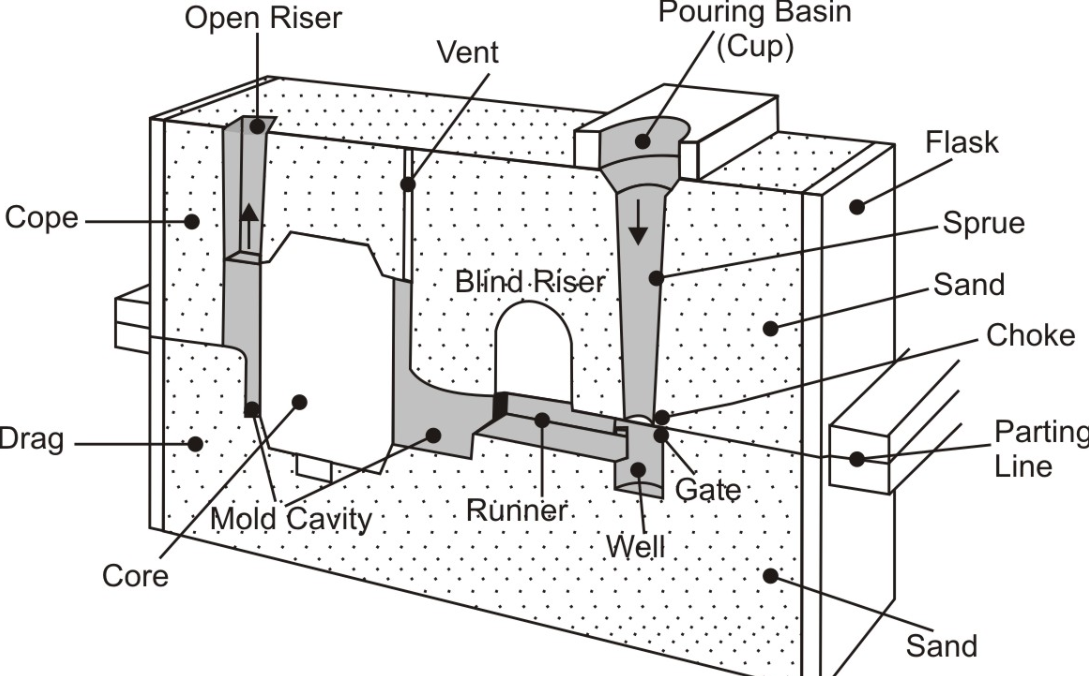
5 Key Components
The gating system has five separate parts. Each part does one specific job in metal casting. These components work like a relay team. One passes molten metal to the next. Know each piece to design better casting systems and avoid defects.
Pouring Basin
The pouring basin sits at the very top of the gating system. Molten metal first enters here from your ladle. The basin looks like a funnel or bowl carved into the top of your mold.
Main Functions:
– Receives molten metal from the pouring ladle at varying pour rates
– Creates a steady stream that feeds the rest of the system
– Acts as the first filter by letting slag and debris float to the top, of course, it can also be used with ceramic filters or filter screens
– Provides a buffer zone that absorbs sudden changes in pouring speed
Basin size matters. Too small? Metal overflows during pouring. The worker struggles to control the ladle. Too large? You waste mold material and floor space. Most pouring basins hold 1.5 to 2 times the volume that flows through per second.
Smart basin design includes a rounded bottom. Sharp corners create turbulence. Turbulence mixes air into the metal stream. Air bubbles travel down into your casting. Round transitions keep flow smooth. The metal slides down the walls instead of splashing.
Some advanced basins use offset entry points. The sprue opening sits off-center from where metal pours in. This offset forces metal to swirl around the basin walls first. Heavy slag stays on top. Clean metal drops through the sprue opening at the bottom.
Sprue
The sprue is a vertical channel. It drops molten metal straight down from the pouring basin to the runner system below. Think of it as an elevator shaft for liquid metal.
Critical Design Features:- Tapered shape: The sprue narrows as it goes down. The top diameter is wider than the bottom. This taper stops aspiration. Aspiration happens as falling metal creates a vacuum that sucks air into the flow. Trapped air creates holes in your casting.- Smooth walls: Any rough spots or steps cause turbulence. Modern sprues get machined smooth or use ceramic sleeves for sand molds.- Controlled height: Taller sprues give metal more falling speed. Higher velocity increases erosion at the sprue base. Shorter sprues don’t build enough pressure to fill the mold.
The sprue bottom connects to the runner system through a sprue base or well. This well is a small pocket that catches the first metal rush. The falling stream hits the well instead of slamming into horizontal runners. This impact zone absorbs energy. Metal calms down before spreading sideways.
Sprue Sizing Calculations:
Foundries calculate sprue size using Bernoulli’s equation and flow rules. The choke area (narrowest point) controls total metal flow rate. Engineers pick choke sizes based on:
– Total casting weight
– Required filling time
– Metal type and temperature
– Number of mold cavities being filled
A typical Gray Iron casting uses filling times of 5-15 seconds. Aluminum alloys fill faster at 2-8 seconds. The sprue choke must pass enough metal to hit these targets.
Runner System
Runners are horizontal channels. They spread molten metal from the sprue base across to multiple gates or casting cavities. The runner acts like a distribution network. One sprue feeds many locations.
Runner Layout Types:
– Single runner: One straight channel connects sprue to one gate. Simple castings use this.
– Multiple runners: Branches split from a main runner trunk. Each branch feeds a different gate or cavity. Multi-cavity molds use this.
– Radial runners: Channels spread out in a star pattern from the sprue. You see this in symmetrical castings.
Runner cross-section shapes vary. Round channels flow best but are hard to make in sand molds. Trapezoidal (wider at top, narrow at bottom) works better for sand casting. The angled sides draft from pattern removal with ease. Rectangular runners are easiest to machine but create corner turbulence.
Runner Sizing Rules:
The runner cross-section area should equal or exceed the sprue choke area. Smaller runners restrict flow. Metal backs up in the sprue. Pressure builds in an uneven way. Much larger runners waste metal and cool the stream too fast.
Most runner systems keep the same cross-section throughout their length. Some advanced designs reduce runner area as branches split off. This maintains flow velocity. Equal velocity at all gates means all cavities fill at the same rate.
Strategic Features:
– Slag traps: Dead-end pockets branch off the main runner. Slag and dross flow into these traps and get stuck. Clean metal continues past to the gates.
– Skim cores: Ceramic or sand cores placed in runners create a dam. Metal flows under the dam. Floating trash can’t pass through.
– Runner extensions: Extra runner length past the last gate gives slag somewhere to go. This extension fills with junk metal. The actual casting cavity gets clean metal.
Gate
Gates are the final channels. They connect runners to the actual mold cavity where your part forms. Molten metal enters your product space here. Gate design has huge impact on casting quality.
Gate Placement Strategy:
Gates should enter at the thickest section of your casting. Thick sections take longest to solidify. Placing gates here keeps a liquid metal path open. The gating system feeds extra metal as the casting shrinks during cooling. This stops shrinkage voids.
Never gate into thin sections first. Thin areas freeze fast. They block off the metal before thick sections finish solidifying. You get internal shrinkage holes in the thick parts.
Common Gate Types:
Top gates: Enter from the mold’s top surface. Simple to make. Metal falls into the cavity. This creates maximum turbulence and oxidation. Used for rough castings where quality doesn’t matter much.
Bottom gates: Enter at the lowest point of the cavity. Metal rises upward as it fills. This cuts turbulence. Air and gas escape upward ahead of the rising metal. Produces cleaner castings than top gating. Requires more complex mold design.
Parting line gates: Enter at the mold’s horizontal joint where cope and drag meet. Easy to cut into the mold. Most common gate location in sand casting. Metal enters sideways into the cavity.
Multiple gates: Several small gates feed one cavity from different points. This speeds up filling. It also balances metal flow for better solidification. Complex parts often need 3-6 gates positioned around the cavity.
Gate Sizing:
Gate cross-section is the smallest area in the entire gating system for most designs. This choke point controls filling speed. Too small means long filling time. Metal cools too much before the mold fills. You get cold shuts or misruns.
Too large causes violent entry. Metal erodes the mold cavity walls. Sand bits contaminate the casting. Gates also need removal after casting. Bigger gates mean more grinding work and metal waste.
Industry practice: total gate area runs 1.5 to 3 times the choke area. For multiple gates, divide this total area among all gate locations. Equal-sized gates give balanced flow. Different gate sizes let you control filling sequence.
Riser (Feeder)
The riser isn’t part of the gating pathway. But it’s essential to the system’s function. Risers are reservoirs attached to the casting cavity. They hold extra molten metal.
Why Risers Matter:
Metal shrinks as it cools from liquid to solid. Most metals lose 3-7% volume during this change. Without risers, the casting pulls inward as it shrinks. Internal voids form in the thickest sections. These shrinkage holes wreck mechanical properties.
Risers stay liquid longer than the casting. They feed more metal into the casting as it contracts. This makes up for shrinkage. The cavity stays packed with metal. Solidification happens from the gates toward the risers. Shrinkage voids form inside the riser instead of the casting. You cut off the riser afterward and recycle the metal.
Riser Design Requirements:
– Volume ratio: Riser must hold enough metal to feed shrinkage. Minimum 1.2 times the volume of the section it feeds.
– Modulus: The riser’s cooling modulus (volume divided by surface area) must exceed the casting’s modulus. This makes sure the riser freezes last.
– Connection: The riser neck connects the riser to casting. This neck must stay liquid long enough for feeding. But it should be small enough to break off with ease.
Riser Types:
Open risers (live heads): Connect to the gating system. Metal flows through them into the cavity. They act as both gate and feeder. Simple but less efficient.
Blind risers (dead heads): Sit on top of the casting with no gating connection. They feed metal, not fill the cavity. Better feeding efficiency but require separate gates.
Atmospheric risers: Open to air at the top. Easy to check metal level during pouring. Metal surface oxidizes from air exposure.
Closed risers: Enclosed in the mold. Less oxidation. Harder to verify proper filling.
Feeding Distance:
One riser can’t feed the entire casting. Metal can’t flow through solidifying material. Each riser feeds a limited distance. This feeding distance depends on:
– Section thickness (thinner sections = shorter distance)
– Metal alloy (long-freezing-range alloys feed less distance)
– Mold temperature and cooling rate
steel castings: one riser feeds about 4-5 times the section thickness in radius. A 2-inch thick steel section needs risers every 8-10 inches. Aluminum has shorter feeding distance. Gray iron feeds well because it expands a bit during graphite formation. It needs fewer risers than steel.
Riser Optimization:
Risers represent pure waste. You pay to melt this metal. It takes up mold space. Then you cut it off and remelt it. Making risers smaller saves money.
Methods to reduce riser needs:
– Exothermic sleeves: Ceramic sleeves around risers that generate heat. They keep riser metal hot longer with less volume needed.
– Insulating sleeves: Slow riser cooling to extend feeding time.
– Chills: Metal blocks placed in the mold to speed cooling in specific spots. This controls solidification direction and cuts riser needs.
– Directional solidification design: Shape the casting so thick sections are near risers. Thickness reduction guides freezing from thin to thick areas.
These five components – pouring basin, sprue, runners, gates, and risers – form a complete gating system. Each component needs careful sizing and positioning. Get one piece wrong and the whole system fails. Your casting comes out with defects. Know how these parts work together to design gating systems that produce quality castings.