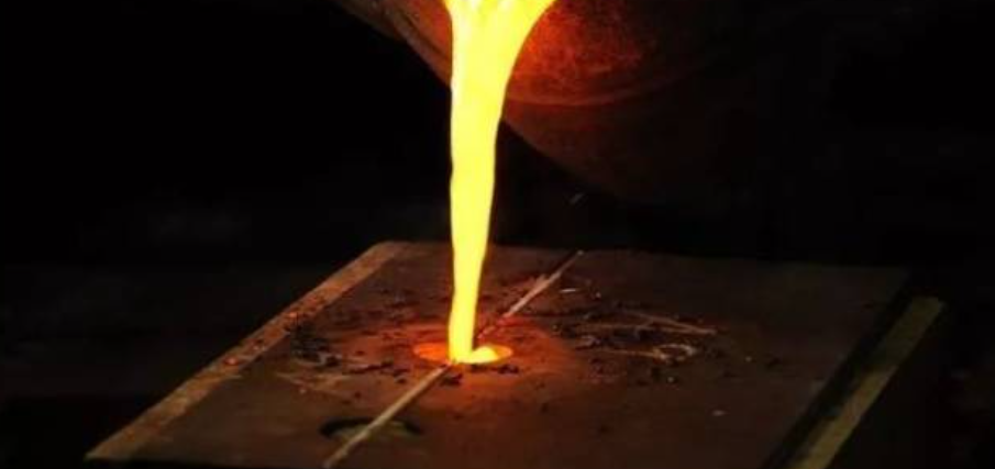
Every metal caster knows this moment: a good casting comes out of the mold. Then you see rough surface defects. The structure looks weak. Or worse—the entire part is scrap.
Many of these failures have one persistent cause. Slag inclusion in casting costs the industry millions each year.
These unwanted non-metallic bits don’t just look bad. They create stress points that can cause major failures in critical parts.
You might be fixing high rejection rates on your production floor. Or you’re choosing components for high-stakes uses. Either way, you need to know what causes slag inclusion. You need to know how to stop it. This isn’t optional—it’s essential.
Spot the warning signs during the pour. Use prevention strategies that work in real conditions. You’ll find practical solutions backed by metal science. Foundries around the globe have proven these methods work.
Here’s what stops these defects from reaching your quality inspector’s desk.
What is Slag Inclusion? (Core Definition & Impact)
Slag inclusion traps non-metallic materials inside metal during casting. These materials include oxides, sulfides, and nitrides. They embed in the metal’s solid structure.
These foreign particles come from the smelting process. Molten metal produces slag that contains oxides, metallic elements, and impurities. This slag should separate and float away. Sometimes it doesn’t. You get a problem embedded in your casting.
The chemistry tells the real story. Slag inclusions contain compounds like magnesium oxide (MgO), aluminum-magnesium oxides, and sulfides. These include MgS and manganese sulfide (MnS).
Steel shows MnS in three forms. Type I creates sharp-edged crystals. Type II makes stringy formations in continuous casting. Type III produces spherical shapes.
The liquid metal becomes supersaturated. Temperatures drop during solidification. The compounds precipitate out.
How Slag Inclusions Destroy Metal Performance
The damage runs deep. Tensile strength drops. Cracks spread from inclusion sites in cast parts.
Steel applications suffer from these non-metallic particles. They harm mechanical properties. They cut weld strength and durability.
Aerospace and automotive parts face high stress loads. Slag inclusions cause catastrophic failures in these applications.
Inclusion size and density follow a pattern. Crystal structure determines this. Columnar structures and equiaxed grains set concentration levels. Segregation channels pack more inclusions. This creates weak zones in the worst spots.
Here’s the paradox in nodular cast iron: MgO and MgS inclusions help the material. They serve as starting points for graphite nodules.
But excess dross causes problems. This mix contains magnesium sulfide, oxide, and silicone. It stays in the metal as defects.
More sulfur means you need more magnesium. This creates more dross inclusions.
Iron castings face another issue. Manganese-silicon slags react with carbon monoxide. They form slag-bubble combinations. These get trapped in the structure.
Internal vs. Surface: Two Different Problems
Internal slag inclusions hide below the surface. They form irregular shapes deep in the metal.
Your eyes can’t spot them. Ultrasonic testing shows their presence. X-ray inspection works too. They cluster in segregation channels. Solutes build up there during late-stage solidification.
Surface slag inclusions show up on the outside. You’ll see irregular, bubbly formations on casting surfaces. The top of molds and cores get hit hard. Gas pores often appear with them.
The inclusions float during the pour. Or they stick out from metal-slag reactions at the surface.
Welding operations trap non-metallic particles between weld beads and layers. Several factors cause this. Poor technique creates problems. Too much travel speed hurts quality. Not removing slag between passes leaves defects. Rapid cooling rates add to the issue.
The result? Surface defects you can see. Strength loss in critical joints you can measure.
Root Causes of Slag Inclusion
Slag doesn’t just show up in your castings. It follows patterns based on chemistry, physics, and how you run operations. Know where slag starts, and you can stop it.
Raw Material Chemistry Sets the Stage
Your charge materials shape slag formation before you pour. Too much oxide content in scrap or ingots? Problems start right away. Reactive metals like aluminum and magnesium have high oxygen levels. This triggers slag formation fast. These elements oxidize at lower temperatures than expected.
The math is simple: more oxygen in your charge means more slag. Impurities in raw materials make it worse. You’re not just working with alloy components. Every contaminant in your source metal fights against you.
Each alloy behaves different. High manganese steel needs aluminum-carbon immersion nozzles. Why? Standard nozzles wear out faster. What happens to the worn material? It turns into slag inclusions.
Melting Process Chemistry Generates New Slag
Molten metal reacts with everything. Oxygen attacks metal parts to form oxides. These oxides float away or get trapped.
Temperature control picks which happens. Low temps speed up slag formation. The metal can’t hold compounds in solution. They turn into solid particles.
Some slag comes from what you add on purpose. Alloying elements and refining agents cause chemical reactions. These reactions make slag as a side effect. You can’t avoid it—but you can manage it.
Non-metal parts in your charge oxidize during melting. The slag should separate clean. It doesn’t always work that way. Then you’ve got inclusions ready to form.
Pouring Parameters Create Critical Moments
Low casting temps spike inclusion rates. The metal gets thick. Slag can’t escape before the metal hardens and locks it in place.
Slow pouring makes things worse. Air exposure goes up. Oxidation increases. More slag forms. More slag gets stuck.
Turbulence during the pour pulls slag in through the flow. The moving metal drags surface slag into the bulk liquid. Raise your pouring temp. Pour faster. Both steps cut inclusion formation.
Welding shows the same issues. Low amperage and slow electrode movement make slag move slow. Big electrodes make too much slag. The result? Slag trapped between weld passes.
Mold Environment Introduces External Contaminants
Your mold cavity reacts too. Impurities in molding materials make slag the moment they touch molten metal. Too much inert dust or not enough bentonite in sand molds? The bonding gets weak. Particles break loose during the pour.
Oxygen stuck in the mold cavity oxidizes the metal surface. These oxides become inclusions you can see on the surface—and ones you can’t see inside.
Dirty mold surfaces add foreign stuff to your casting. Leftover sand, dust, or coating bits mix with the metal. Mold material pulled into the liquid gets stuck inside as inclusions.
Refractory quality matters in continuous casting. Bad refractories wear down under heat stress. Where does the worn material go? Into your casting as slag.
Pouring System Design Controls Fluid Dynamics
Nozzle depth makes a big difference. Shallow depths (≤80 mm) give you a slag spot index of 2.85. Go deeper to 125-140 mm and the index drops to 0.95. Past 145 mm? You get 0.85.
The science is simple. Deeper immersion keeps the mold liquid level steady. A steady level stops surface slag from getting pulled down into the metal.
Bad nozzle overlap in continuous ops creates empty spaces. Slag fills these spaces during rough flow. Multi-pass welding with too much undercut or uneven profiles traps slag between layers.
Fast casting speed changes mess everything up. The mold liquid level jumps around. Protective slag that should stay on top mixes into the bulk metal. aluminum oxide inclusions form. Thick powder makes the problem worse.
Operational Variables Amplify Every Risk Factor
Instability ruins quality. Molten steel level shifts during pouring, speed changes, or nozzle swaps make flow patterns unpredictable. Unmelted protective slag gets into the casting. Al₂O₃ inclusions grow.
Bad vibration settings in continuous casting break up slag separation. The slag layer falls apart. Particles get into the hardening metal.
Calcium aluminate and aluminum oxide make strip-like black lines on cold-rolled plates. You’ll spot these defects in finished products—long after casting ended.
The fix needs full system control. Keep mold liquid levels stable. Maintain immersion depth above 125 mm for slag indices below 1.0. Install slag traps and full pouring basins. Cut turbulence at every transfer point. Clean mold cavities well. Pick higher bentonite or montmorillonite binding capacity in your molding sand.
Each factor links to the others. Fix one and risk drops. Fix all of them and you remove the root causes of slag inclusion.
Proven Prevention Methods
Slag inclusion prevention is like managing heart disease. You need multiple fixes working together. One solution won’t cut it. Systems that work together win.
metal casting shops that cut inclusion rates close to zero use proven steps. These methods work together. Each one makes the others stronger. The proof is clear: shops using combined prevention see rejection rates drop 70-80% compared to random, reactive fixes.
Pre-Melting Material Control
Start before you light the furnace. Raw material quality sets your baseline slag risk.
Screen every scrap batch for oxide content. Set limits: 2% for aluminum alloys, 1.5% for steel grades. Reject batches above these limits. High-oxide scrap costs more in rejections than clean material.
Reactive metals need closer checks. Magnesium and aluminum oxidize at 450°C. That’s well below melting temps. Store these in sealed, low-humidity spaces. Measure moisture on arrival. Target <0.5% water by weight.
Charge material order matters. Load dense, clean ingots first. Add scrap in small amounts during melt. This cuts turbulence. Air entrainment drops by 40% compared to dumping mixed charges.
Track material batches through production. Inclusion spikes? Trace back to source lots. Drop suppliers with repeat contamination.
Melt Chemistry Optimization
Control temperature within ±5°C of target superheat. Low temps cause early precipitation. Slag forms before it can separate. High temps speed up refractory erosion. This creates new inclusion sources.
Degassing removes dissolved oxygen that forms oxides. Argon purging for 8-12 minutes cuts oxygen levels from 80 ppm to <15 ppm in aluminum. Nitrogen works for steel. Flux choice depends on alloy chemistry. Sodium-based fluxes for aluminum. Calcium-based for steel.
Add deoxidizers in measured amounts. Aluminum kills oxygen in steel at 0.01-0.03% addition rates. Silicon and manganese work for cast iron. Too much creates new inclusions from the deoxidizer. Too little leaves active oxygen.
Monitor slag chemistry in real-time. Basicity ratios (CaO/SiO₂) between 1.2-1.5 give best slag flow in steel. Adjust with lime or silica. Fluid slag separates clean. Thick slag traps in metal.
Pouring System Engineering
Nozzle depth affects inclusion rates more than most factors. Continuous casting data shows this clearly: keep 125-140mm depth for slag indices below 1.0. Shallow pours (under 80mm) triple your inclusion risk.
Basin design controls turbulence. Full pouring basins keep metal calm. Calculate basin volume at 2.5× max flow rate. Install weirs and screens to trap surface slag. Position these to create smooth flow. Reynolds numbers below 2,300.
Stopper rod control stops level swings. Automated systems beat manual operation. Mold level changes above ±3mm pull surface slag into casting zones. Servo-controlled stoppers hold ±1mm stability.
Filter placement removes 95% of inclusions larger than 30 microns. ceramic foam filters work for aluminum and iron. Position filters flat in runner systems after the sprue turn. Vertical placement cuts effectiveness by 30%.
Mold Preparation Standards
Clean cavities cut 60% of external inclusion sources. Blow compressed air at 90 PSI through all passages. Follow with vacuum extraction to pull fine dust. Keep residual sand content below 0.1 g/m².
Coating quality stops mold erosion. Use alcohol-based coatings in three thin layers. Skip the thick single coat. Each layer needs full drying before the next. Wait 15 minutes minimum between coats. Target coating thickness of 0.3-0.5mm. Thicker coatings crack and fall into the metal.
Bentonite content in green sand affects binding strength. Test samples should show 8-10% active bentonite. Lower levels let sand grains break free during pouring. Add montmorillonite clay to boost binding. This keeps permeability unchanged.
Core quality needs separate checks. Look for surface breakdown. Reject cores that shed material with light brushing. Store assembled cores in humidity-controlled areas. Keep 40-50% relative humidity. This stops moisture pickup that weakens binders.
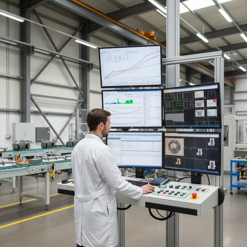
Real-Time Process Monitoring
Install immersion thermocouples in pouring ladles. Temperature drops of 15°C during transfer boost slag formation fast. Preheat ladles to within 50°C of metal temperature. Insulate transfer systems.
Flow rate sensors catch turbulence events. Set alarms at ±10% of target pour speed. Check and fix any swings right away. Don’t finish the heat.
Slag detection systems use electromagnetic sensors. These units spot non-metallic particles in molten streams. Auto-reject systems move contaminated metal away before mold contact. Success rate: 98.5% detection accuracy for particles >5mm.
Document every parameter. Compare production data against rejection rates each week. Statistical process control spots drift before it causes scrap. Control charts showing upward trends trigger fixes. Don’t wait for failures.
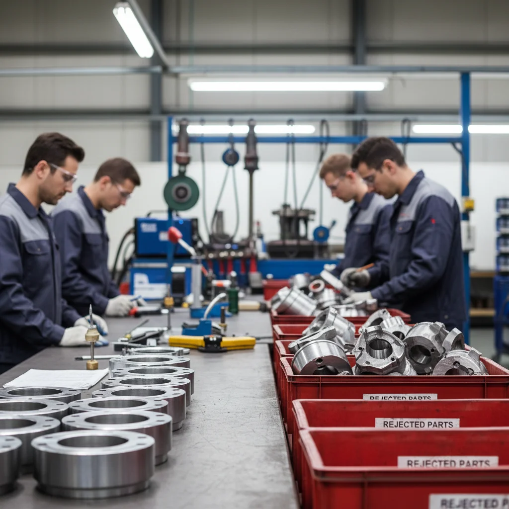
Detection & Quality Control
Quality inspectors use advanced tools to catch defects that prevention methods miss. The automated industrial quality control market shows this shift—growing from USD 896.7M in 2026 to USD 1.38B by 2032 at 7.4% CAGR. Metal casting operations now use detection systems. These systems blend traditional methods with AI analysis.
Non-Destructive Testing Methods That Work
Ultrasonic testing sends high-frequency sound waves through castings. Slag inclusions reflect these waves in a different way than solid metal does. The equipment shows inclusion size, depth, and location. Accuracy reaches 98% for defects larger than 3mm. This method works best for thick-section castings. Internal defects hide deep in these castings.
X-ray inspection creates 2D images. These images show density variations. Slag appears as dark spots against lighter metal. Modern 3D CT scanning builds complete internal maps. You see every inclusion in three dimensions. No destructive testing needed. The semiconductor metrology and inspection market—USD 8.88B in 2026, climbing to USD 11.47B by 2030—drives CT technology advances. Metal casting benefits from these advances.
Eddy current testing finds surface and near-surface inclusions in conductive metals. The probe creates electromagnetic fields. Inclusions disrupt these fields. Changes in current flow show defect locations. This works fast on production lines. Scan speeds hit 2 meters per minute on continuous casting surfaces.
Repair Solutions & Remediation

Slag inclusions don’t always mean scrap. Your repair choice depends on three factors: how bad the defect is, how critical the part is, and what it costs. The disaster restoration services market shows USD 42.93B in 2025. It climbs to USD 70B by 2033. This proves fixing problems costs less than replacing everything. Metal casting works the same way.
Surface Inclusion Repair Techniques
Grinding removes shallow surface inclusions. Take the defect out fully. Go 2-3mm past what you can see. Blend edges smooth. This stops stress from building up. Check depth with ultrasonic testing before you grind. You don’t want to thin critical walls.
Wire brushing cleans slag from weld inclusions between passes. Remove every trace before the next bead. Pneumatic needle scalers work faster on heavy slag buildup. Check with dye penetrant after cleaning. Any slag left shows up bright.
Welding fills cavities left after grinding. Preheat the base metal. This cuts thermal shock. Match filler metal chemistry to the casting alloy. Use low hydrogen electrodes for steel repairs. Build up the area in thin layers. Remove slag after each pass before the next one.
Post-weld heat treatment relieves stress left behind. Skip this step and cracks form later. Hold at 600-650°C for one hour per 25mm of thickness. Slow cooling stops new problems.
When Repair Makes Economic Sense
Cost comparison drives your choice. Property restoration shows USD 52.79B in spending for 2025. Why? Fixing costs 30-40% less than replacement in most cases.
Small surface inclusions in non-critical zones get repaired often. The water damage restoration segment—38.56% market share—shows similar numbers. Fix what you can. Replace what threatens safety.
Internal inclusions in stress-bearing sections need rejection. No repair method brings back original strength in these spots. Aerospace and medical device castings get zero tolerance. One failure costs more than a thousand good parts.
Commercial operations show CAGR 6.15% growth in restoration services. Metal casting shops use the same idea: invest in repair tools for defects that fix well. Reject the rest fast. Don’t waste time on fixes that won’t work.
Industry-Specific Considerations
Casting tolerance for slag inclusion changes dramatically between industries. A surface defect that works fine in farm equipment will destroy an aerospace component’s certification. Know your industry’s specific requirements. This shows you which prevention methods need investment and which defects mean automatic rejection.
Aerospace: Zero-Tolerance Environment
Aircraft engine parts and structural components face the strictest standards. Any detectable slag inclusion means automatic scrap. ASTM E155 and AMS specifications require 100% inspection using multiple NDT methods. X-ray must show zero internal gaps larger than 0.5mm. Ultrasonic testing checks this at even tighter limits.
The reason is simple: one inclusion can start a fatigue crack at altitude. Temperature swings from -55°C to 650°C stress inclusion boundaries. Catastrophic failure follows. Investment casting for turbine blades uses vacuum melting and controlled solidification. This cuts inclusion rates to parts per million. Each blade costs USD 10,000-50,000 to produce. Quality systems justify this expense.
Automotive: Balance Between Performance and Economics
Engine blocks, transmission housings, and suspension parts tolerate small inclusions in non-critical zones. Maximum size limits run 2-3mm for Class B castings. High-stress areas like cylinder heads need Class A standards. Zero inclusions above 1mm.
Production volumes change the math. Foundries making 500,000 cylinder heads per year invest in automated ultrasonic scanning and AI visual inspection. Detection speeds hit 15 parts per minute. Rejection rates below 2% justify the equipment cost. Electric vehicle parts demand tighter control. Manufacturers push weight reduction through thinner wall sections.
Heavy Machinery: Durability Over Precision
Mining equipment, industrial gears, and construction machinery parts accept larger inclusions. Service life matters more than surface finish. Slag inclusions under 5mm seldom cause field failures in applications with safety factors above 3:1.
Visual inspection catches major defects. Spot ultrasonic testing checks critical load paths. The repair threshold sits higher here. Grinding and welding fix surface inclusions up to 8mm deep. Post-weld stress relief brings properties close to original specs. Component replacement costs—USD 50,000 for large crusher housings—make repair the smart choice financially.
Conclusion
Slag inclusion in casting doesn’t have to be a manufacturing headache. Preventing slag inclusion comes down to three factors you can control: proper gating design, careful mold preparation, and disciplined pouring techniques. Understanding the root causes helps. Turbulent metal flow, poor slag removal, or damaged mold coatings all create defects. Know these causes, and you can stop problems before they start.
The financial impact is clear. Every rejected casting costs you material, labor, energy, and customer trust. The detection methods and prevention strategies we’ve outlined do more than reduce scrap rates. They build your reputation for consistent quality. This sets you apart in competitive markets.
Ready to take action? Start with a full audit of your current slag management practices. Find your biggest weakness. Is it gating? Materials? Process control? Then use the targeted solutions we’ve covered. Small changes in these areas often bring big improvements in casting quality. Your next perfect pour is closer than you think.