Scrapped castings. Rework costs climbing. A customer rejection just landed in your inbox.
Porosity keeps showing up in your parts. You know the frustration. But most shops fix the symptom, not the root cause.
Why your castings have porosity isn’t always a clear answer. Gas porosity and shrinkage porosity look alike on the surface — but they need different fixes. Confuse one for the other, and the problem comes back.
This guide goes straight to the diagnosis. You’ll see what’s happening inside your metal, where the defects start, and which process and design changes stop them for good.
Firefighting a live production issue? This gives you a fast path to the fix. Building a long-term prevention system? You’ll leave with a solid action plan for that too.
What Is Casting Porosity — And Why It’s Costing You More Than You Think
Porosity sounds like a technical term. It’s more than that — it’s a void, a hole, a gap that forms inside your casting during pouring and solidification. Where it sits determines everything. Some locations cost you nothing. Others cost you the entire part.
That difference is bigger than most buyers and engineers expect.
Three types. Three very different outcomes:
-
Fully enclosed porosity — buried deep inside, invisible to the eye. Harmless at first, until a machine tool cuts through and exposes it
-
Blind porosity — open on one surface. It bleeds through paint, pulls in moisture, and slowly breaks down parts while they’re in use
-
Through porosity — a tiny channel that runs straight through the wall. In hydraulic or pneumatic components, that’s a direct leak path. The part fails. No middle ground
Two root causes drive most casting porosity problems:
-
Gas porosity — trapped gases from rapid cooling, poor venting, or contamination
-
Shrinkage porosity — voids left behind as metal contracts during cooling, with no fresh metal feeding in to fill the gap
Shrinkage porosity is the harder one to fix — and timing is the reason. Pressure applied during solidification pushes it back. Pressure applied after the metal sets does nothing at all.
Target the wrong type with the wrong fix, and the defect returns every single time.
Gas Porosity vs. Shrinkage Porosity: Diagnose Which One You’re Dealing With
The fastest way to waste a week of rework? Treat shrinkage porosity like a gas problem.
These two defects share a name and almost nothing else. Their shapes differ. Their locations differ. And their fixes are opposite — not just different, but reversed. Get the diagnosis right before you touch a single process variable. That’s what separates solving the problem from chasing it in circles.
Here’s how to tell them apart.
What They Look Like
Shape is your first clue — and it’s reliable.
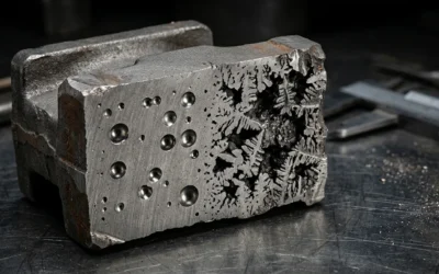
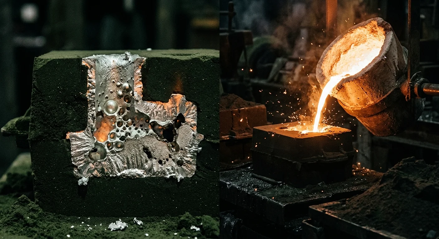
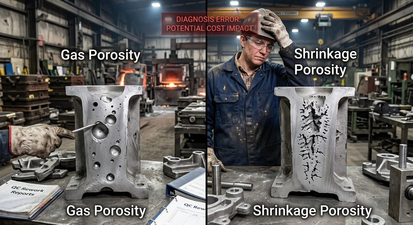
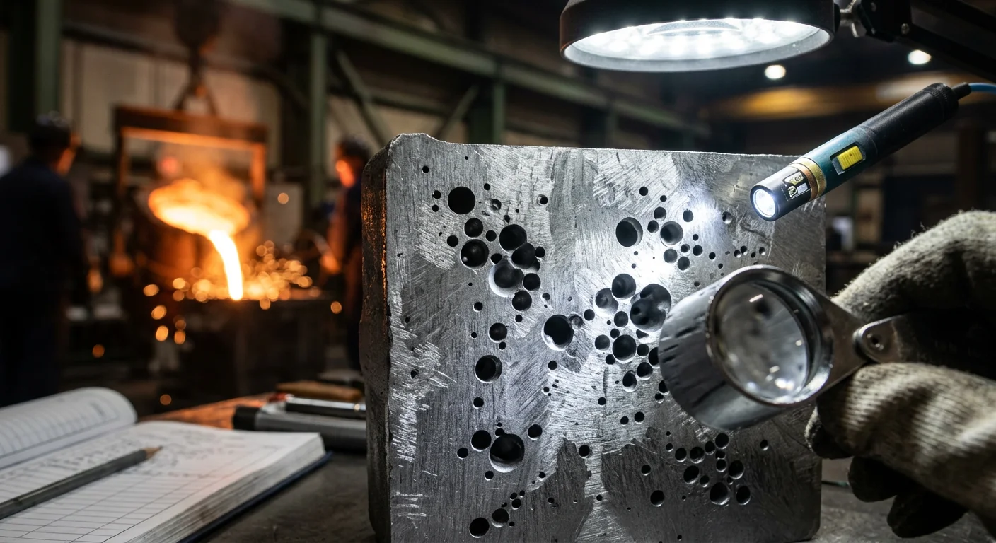
Gas porosity has clean, smooth walls. Round, elliptical, sometimes pear-shaped. The inner surface often looks oxidized, almost shiny under light. Each void sits on its own, separate from the others.
Shrinkage porosity looks like something tore through the metal from the inside. You’ll see irregular edges. Jagged, branching walls. Cracks that connect and spread in a network. There’s no clean geometry — just rough, fractured surfaces that follow the solidification path.
Where They Show Up
Location tells you nearly as much as shape.
|
Feature |
Gas Porosity |
Shrinkage Porosity |
|---|---|---|
|
Shape |
Round / elliptical / smooth |
Irregular / dendritic / jagged |
|
Wall surface |
Smooth, oxidized |
Rough, uneven |
|
Location |
Upper casting / low-vent zones |
Hot spots / thick junctions / centerline |
|
Distribution |
Isolated, random |
Directional, networked |
|
X-ray appearance |
Uniform spherical voids |
Elongated, interconnected cavities |
Gas porosity clusters toward the top of the casting and in areas where trapped gas had no exit. Shrinkage porosity forms at hot spots — thick sections, rib-wall junctions, anywhere the metal stayed liquid longest. The surrounding material solidifies first. That cuts off the feed path. The void forms where the liquid ran out.
Four Field Tests That Confirm the Diagnosis
Don’t guess. Run the test.
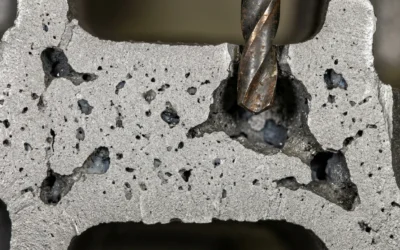
-
Cut and polish — Cross-section the suspect area and polish the face. Smooth inner walls point to gas. Rough, branching surfaces confirm shrinkage. This one test gives you 90%+ confidence.
-
Dye penetrant — Apply dye to the surface. Round marks suggest gas. Irregular, branching patterns suggest shrinkage.
-
Pressure test — Pressurize the casting. Leaks that trace back to round, connected voids point to gas porosity. Isolated shrinkage voids rarely form a continuous leak path.
-
X-ray or CT scan — Gas shows as uniform, spherical pockets spread across the affected zone. Shrinkage shows as elongated, directional cavities lined up along the solidification path.
Your Diagnosis Sequence
Work through this in order:
-
Step 1 — Check location. Upper casting or scattered distribution? Suspect gas. Centerline, thick junctions, or hot spots? Suspect shrinkage.
-
Step 2 — Cut and polish. Smooth walls confirm gas. Rough, branching walls confirm shrinkage.
-
Step 3 — Run a pressure test if the part is leak-critical. Round void leakage points to gas.
-
Step 4 — Confirm with X-ray. Shape and distribution will lock in the answer.
Nail the diagnosis first. The process changes, the design adjustments, the prevention systems — none of it works unless you know which defect you’re fighting. Start there. Every other step depends on it.
7 Root Causes of Gas Porosity (And the Exact Signals to Spot Them)
Gas porosity doesn’t just appear. Every void, every blowhole, every scattered pinhole has a specific origin — and that origin leaves evidence. You just need to know what to look for.
Below are the seven causes behind most gas porosity failures in production castings. Each one produces its own set of signals.
Hydrogen Absorption in Aluminum Alloys
Aluminum and hydrogen have a tricky relationship. At 700°C, aluminum melt holds up to 0.7ml of hydrogen per 100g of metal. Drop to solidus temperature and that number falls to 0.04ml/100g. The gas has to go somewhere — and it goes into your casting.
Sources are everywhere. Moisture in scrap metal (just 0.1% H₂O produces 100x its volume in steam), contaminated tools, cutting oils, and humid workshop air above 50% RH all feed the problem.
Signals to spot:
– Round, spherical pores between 0.1–1mm diameter, spread evenly across the section
– Subsurface blowholes visible on X-ray
– Higher porosity counts in remelt scrap versus virgin ingot batches
The line in the sand: Once dissolved hydrogen passes 0.2ml/100g, porosity is unavoidable.
Poor Mold Venting
Trapped air has one option when metal arrives — it pushes back. Undersized or badly placed vents let back-pressure build above 0.5 bar. That pressure fights the incoming metal and creates resistance pockets. Those pockets become voids.
The standard people ignore most often: vent area below 1mm² per cm of mold area is not enough. Full stop.
Signals to spot:
– Elongated pores running parallel to mold walls and surfaces
– Blowholes clustered at thick sections where gas has no exit
– Fill simulations showing bubble formation at pressures above 0.3 bar
Your threshold: Keep vent land width under 10mm. Your mold fill simulation shows back-pressure peaks above 1 bar? The venting system has already failed — before a single pour runs.
Excessive Moisture in Sand Molds
One gram of water turns into 1,700 times its volume in steam at melt temperatures. Sand moisture content above 0.3% is not a small variable. It’s a steam generator sitting inside your mold.
Binder breakdown between 100–200°C makes it worse. Steam can’t vent fast enough. It punches straight into the solidifying metal.
Signals to spot:
– Surface pinholes and blisters ranging 0.5–2mm across
– Open holes visible on the casting skin right after shakeout
– Rounded pores spread through the section in sand-cast aluminum
The number that matters: Green sand moisture above 0.4% doubles defect rates. Target below 0.2% and keep it there.
Turbulent Pouring and Air Entrainment
Fill velocity above 0.5 m/s stops being metal flow and turns into chaos. Turbulent metal folds air into itself — anywhere from 1% to 5% trapped air by volume. Every fold becomes a future defect.
Sharp corners in gating geometry, missing filters, and oversized runners all add to the damage. The metal reaches the mold cavity already loaded with its own gas.
Signals to spot:
– Rounded gas holes between 1–3mm, localized rather than spread out
– Wormhole formations in fillets and inside corners
– Flow simulations showing vorticity above 10⁴ s⁻¹
What to change: Drop fill velocity below 0.3 m/s. Taper your runner diameter at a 1:10 ratio. Clean up the gating geometry. Cut out every sharp transition the metal has to pass through.
Degassing Failure
Skip degassing — or run it underdosed — and dissolved hydrogen sits in the melt waiting to nucleate. A rotary degassing treatment under 5 minutes, or purge flow below 0.5 l/min of argon or nitrogen, won’t pull out enough hydrogen to matter.
Residual hydrogen above 0.15ml/100g after treatment means the treatment didn’t work.
Signals to spot:
– Fine, scattered porosity below 0.5mm, spread evenly through the cross-section
– No drop in defect rate after adding the degassing step
– X-ray showing uniform gas entrapment with no hot-spot clustering
The benchmark: Effective degassing pulls dissolved hydrogen from 0.4ml/100g down to below 0.1ml/100g. Validate it with a reduced pressure test. Foam height above 50mm on the RPT sample means you’re not there yet.
Contaminated Charge and Melt
Dirty scrap hides its problems until you cut the casting open. Oils, cutting fluids, and oxide buildup in the furnace all break down at melt temperatures and release gas straight into the liquid metal. Oxide films are especially aggressive — they trap between 2x and 10x their own volume in gas.
Signals to spot:
– Scattered irregular pores between 0.2–1mm, no consistent orientation
– Defect clusters near the gate area where contaminated metal entered first
– Dark spots on raw casting surfaces before any finishing work
What the data shows: Ceramic filters cut porosity by 40–60% in contaminated charge scenarios. Running without filtration on mixed scrap means you’re creating the defects yourself.
Improper Fill and Solidification Dynamics
High-pressure die casting creates its own gas entrapment problems through fill speed and pressure. Shot speeds above 40 m/s shear air into the metal faster than it can escape. Low superheat — below 50°C above liquidus — causes the metal to solidify too early. Gas gets locked in before it can rise out.
Signals to spot:
– Blowholes and blisters concentrated at thermal hot spots
– Gas entrapment occurring pre-solidus, confirmed by simulation
– Simulations showing bubble formation in low thermal gradient zones
The operating window that prevents it: Keep superheat between 50–80°C. Hold shot speed below 30 m/s. Keep piston velocity under 3 m/s. Push outside any of those limits and the process builds its own porosity — no matter what else you’re doing right.
Quick Reference: Gas Porosity Signal Guide
|
Defect Type |
Pore Shape & Size |
Typical Location |
Best Detection Method |
|---|---|---|---|
|
Gas holes |
Round, 1–3mm |
Internal / localized |
X-ray, cross-section |
|
Blowholes |
Spherical, >2mm |
Subsurface |
Microscopy, CT scan |
|
Blisters |
Flat, surface-level, <1mm |
Skin layer |
Visual inspection |
|
Pinholes |
0.1–0.5mm |
Scattered throughout |
Dye penetrant |
Seven causes. Seven distinct signal patterns. Match what you’re seeing to what’s on this list — that’s your starting point. A real fix can’t begin anywhere else.
5 Root Causes of Shrinkage Porosity — And Where It Always Hides
Shrinkage porosity doesn’t spread at random. It follows the metal — more precisely, it follows the last place the metal stops being liquid.
That’s the principle behind every location it shows up, and every cause behind it. The metal contracts as it cools. Fresh liquid can’t always flow in to fill that gap. A void forms. Simple physics. Brutal consequences.
Here are the five causes that drive it — and where the defects land.
Hot Spots at Thick-Section Junctions
Thick walls meeting thin ones causes heat to stack up. The surrounding metal solidifies first. That cuts off the liquid pool at the junction. The isolated pocket contracts with nothing feeding it.
You’ll find the voids right there — at rib-wall junctions, boss transitions, and any geometry where section thickness changes fast. Same location, every pour. That consistency is the tell.
Run a thermal simulation. Isolated high-temperature zones in your model mark your future defect sites.
Inadequate Riser Design
The riser has one job: stay liquid longer than the casting it feeds. The feeder neck modulus drops below the casting modulus, and the riser freezes first. The feeding path closes. Macroshrinkage forms in the void left behind.
Riser size, neck geometry, and placement aren’t rough estimates — they’re calculations. Get them wrong and the riser becomes decoration.
Gating System Failures
A gate that freezes before feeding is complete doesn’t just stop — it starves the hot spots. Undersized or badly positioned gates also push turbulent fill. That erodes mold walls and creates uneven heat distribution, which makes the shrinkage problem worse.
Slow the velocity. Cut out turbulence. Design the gate to stay open through the full feeding window.
Alloy Chemistry
Some alloys stay semi-solid across a wide temperature band. This includes certain aluminum series and cast iron with poor carbon equivalent. During that window, dendrite networks trap isolated liquid pockets. Each one becomes a microshrinkage site.
Carbide-forming elements like Cr, Mo, and V block graphite growth in iron. That makes things worse. Low or weak inoculation adds more risk on top of that.
Optimize your CE. Inoculate to the right level. Your alloy has a wide freezing range? The rest of your process needs to make up for it.
Flask Spacing That Traps Heat
Castings packed too close together share heat. That shared thermal mass slows directional solidification. It blocks fast chilling. It keeps heavy sections liquid longer than your feeding system can handle.
The fix is simple — increase spacing so heat can escape and chilling can do its job. Directional solidification needs a clear thermal gradient to work. Crowd the flask and you kill it.
Where Shrinkage Porosity Always Hides
The location pattern is consistent enough to predict:
-
Thick-to-thin transitions — the first place feeding breaks down
-
Thermal hot spots — isolated liquid zones surrounded by solid metal
-
Centerlines of heavy sections — where the last liquid sits with nowhere to go
-
Near risers and gates — those systems freeze too early
-
Between adjacent castings — shared heat pools and slows solidification
One more thing worth tracking: location consistency across multiple castings confirms a feeding or design problem. The void moves between pours? That’s a temperature control issue. It’s always in the same spot? That’s geometry, gating, or riser design — and it won’t fix itself.
High pouring temperature makes every one of these causes worse. It extends the liquid phase, widens the thermal gap, and gives shrinkage more time and space to develop.
Process-Level Fixes You Can Implement This Week
Diagnosis done. Now the work starts.
Most foundries know their porosity type. The problem is they stop there. They run one test, adjust one variable, and wait. Scrap keeps piling up in the meantime. Below is a set of concrete process changes. Each one fits inside a standard production week. Each one targets a specific mechanism that creates voids in your castings.
Pick the ones that match your diagnosis. Run them in parallel where you can.
Attack the Gas Sources First
Gas porosity diagnosis? Your fastest wins come from cutting off the gas supply before it ever reaches the melt.
-
Dry your charge material before it hits the furnace. Moisture is the biggest hydrogen contributor most shops miss. Even small amounts of residual moisture on scrap produce steam. That steam loads your melt with dissolved hydrogen before you pour a single part.
-
Validate your degassing cycle — don’t assume it’s working. Run a reduced pressure test on your next heat. Foam height above 50mm on the RPT sample tells you the treatment is not pulling hydrogen below the 0.1ml/100g threshold. Fix the cycle, not the assumption.
-
Check your vent geometry against your vent area. Vent land width above 10mm? That’s your back-pressure problem. Fix the geometry before you touch anything else.
Tighten the Feeding System for Shrinkage
Shrinkage porosity is a feeding problem. Every fix targets the same goal: keeping liquid metal available at the right location for the right amount of time.
-
Recalculate riser modulus against casting modulus. Your feeder neck freezes before the casting? The riser isn’t feeding — it’s just sitting there. Recalculate and resize it.
-
Slow your pour rate at thick-section transitions. Turbulent fill at junctions spreads heat unevenly. That makes isolated hot spots worse, not better.
-
Add chills at identified hot spots. Don’t wait for simulation confirmation. The defect shows up at the same location every pour? That pattern is your evidence. Act on it.
Build a 30-Day Review Rhythm
One-week fixes need a feedback loop. Without one, they drift back to baseline.
Set up a 15-minute weekly check-in with the people running the process. Not a formal meeting — a quick huddle. Three questions: What changed? What’s the defect rate showing? What’s the next variable to adjust?
Find your top three quick wins in week one. Put them in place. Check the results at 30 days. The shops that cut porosity and keep it down aren’t running more advanced processes. They run tighter feedback cycles on the processes they already have.
Design-Level Solutions That Eliminate Porosity at the Source
Process fixes buy you time. Design fixes buy you permanence.
Porosity keeps coming back after every process adjustment? The geometry is working against you. The metal does what physics tells it to do — and your part design isn’t giving it anywhere better to go. That’s the real problem.
Rethink Your Gating and Riser Geometry
The gating system controls everything before solidification starts. Get the gate-to-runner-to-sprue ratio wrong and you get turbulence. Turbulence pulls in air. Air entrainment means porosity — no matter how clean your melt is.
Here’s what to fix at the design stage:
-
Taper your runners. A constant cross-section creates velocity spikes. A tapered runner keeps flow steady from entry to fill.
-
Use multiple ingates with calculated cross-sectional areas. Coverage matters. Single-point fill throws off the heat balance. Multiple ingates spread the heat load and cut down isolated hot spots.
-
Put the choke at the narrowest section. That’s where you control velocity. Move it and you lose control of fill speed everywhere past that point.
-
Size risers by modulus, not by feel. One automotive casting redesign proved this — simulation-predicted riser placement wiped out shrinkage cavities, confirmed by metallographic examination showing a dense, uniform microstructure. A riser that freezes first feeds nothing.
Design for Directional Solidification
Your geometry should tell the metal where to freeze — thin sections first, thick sections last, risers still liquid the whole time. Build that sequence with purpose:
-
Keep wall thickness transitions below a 2:1 ratio. Go above that threshold and hot spots become almost certain.
-
Add ribs and fillets at transitions. They do more than support structure — they spread heat and keep solidification fronts even.
-
Put insulating sleeves on risers to keep them liquid longer. Add cooling channels near thin sections to speed up their freeze rate.
Validate With Simulation Before You Cut Steel
MAGMA and ProCAST serve one purpose at the design stage: show you the defect before it costs you tooling money. Simulation-guided riser placement has cut out shrinkage in trials — before a single pour ran. That’s the right order of operations.
Run your design through simulation. Check venting paths for back-pressure buildup. Confirm that cooling channel placement drives the thermal gradient you need. Add ceramic filters to the gating system to catch inclusions before they reach the cavity.
Post-redesign X-ray results tell the same story every time: better venting plus riser redesign produces clear, measurable gas porosity reduction. Metallographic analysis backs it up — shrinkage cavities gone, microstructure uniform.
The design either feeds the problem or kills it. There’s no middle ground.
Advanced Remediation: The Casting Is Already Made
The casting is poured. The defect is there. That doesn’t mean the part is scrap.
Three remediation paths exist — each with firm limits on what it can and can’t fix.
Hot Isostatic Pressing (HIP) applies heat and pressure together to collapse internal voids. It works on aluminum-silicon alloys (A356, A380, A413) and high-value aerospace alloys like Ti-6Al-4V. The catch: HIP closes voids under 500 μm. Anything above 1mm, it won’t touch. For parts priced above $500/unit, the numbers work in your favor — HIP cuts scrap by 20–50% and improves fatigue life 2–3x.
Vacuum impregnation solves a different problem. It doesn’t restore mechanical strength. It seals leak paths. Anaerobic acrylates or epoxy resins push into micro-porosity between 10–300 μm under 50–100 psi. Then the material cures at 150–200°C. Pressure integrity returns to 100–500 psi. Cost runs $5–20 per part. For pressure-tight housings and hydraulic components, that’s enough.
Switching the process makes sense once porosity exceeds 3–5% in HPDC and patching keeps failing pressure tests. Vacuum casting cuts gas porosity 70–90% in thin-wall sections under 5mm. Low-pressure casting reduces shrinkage by 50% and pulls total porosity below 2%.
|
Method |
Porosity Reduction |
Cost/Part |
Best For |
|---|---|---|---|
|
HIP |
80–95% (< 500 μm) |
$50–200 |
Aerospace / Medical |
|
Impregnation |
90–100% (leaks) |
$5–20 |
Pressure-tight parts |
|
Vacuum casting switch |
70–90% gas |
$10–50 setup |
Thin walls, high-volume |
Match the method to the defect type, part value, and pressure requirements. There’s no universal answer — just the right tool for what’s in front of you.
Porosity Prevention Checklist: Your Pre-Production Quality Gate
Most porosity problems are decided before the first drop of metal moves.
Mold preparation, metal condition, process parameters — all of these lock in before pouring starts. Get them wrong and no downstream fix will save you. This checklist is your last line of defense before production begins.
Six checks. Any red flag stops the pour.
-
Visual — Clean the joint surface 20–50mm from the weld line. No contamination, no exceptions.
-
Mechanical — Grind to bare metal. Use a stainless steel brush on aluminum oxide.
-
Chemical — Wipe with acetone. Zero residue.
-
Gas — Leak-test every hose. Confirm argon purity at 99.99% minimum, with flow between 12–20 CFH indoors.
-
Environment — No drafts. Humidity below 80%. Go above that threshold without preheat and you’re already producing porosity.
-
Final gate — All clear? Start the pour. One red flag? Stop and fix it first.
Quick-Reference by Process
Sand casting: Pour temperature runs 1,350–1,450°C for aluminum. Thick sections solidify in under 30 seconds. Stop production if mold box misalignment exceeds 1mm or you see sand moisture. Wet sand creates steam pores — every time, no exceptions.
Die casting: Hold die temperature at 180–250°C. Injection pressure sits at 50–150 MPa. Pour speed stays at 2–5 m/s. Stop production if speed variance goes past 10% or die cracks appear. Gas porosity above 2% by volume follows right away.
Investment casting: Shell thickness must stay above 6mm and be completely dry. Use vacuum melt. Keep dissolved hydrogen below 2 ppm. Stop production if shell moisture appears — that’s an explosion risk, not just a quality issue.
The Numbers That Matter
-
Acceptable porosity for structural parts: below 1% by volume
-
Preheat at 100–150°C cuts moisture-driven porosity by 50–70%
-
Argon flow above 20 CFH creates turbulence — keep it between 12–20 CFH
This isn’t a bureaucratic quality form. It’s a production decision framework. Foundries that cut scrap rates and hold them down run this check before every pour — not after defects show up.
Conclusion
Porosity doesn’t just happen. It’s the result of decisions made — or skipped — long before molten metal enters a mold.
You now know how to tell gas porosity from shrinkage porosity. You can trace each type back to its root cause. You can apply fixes at every level — from adjusting your gating design to salvaging a casting already off the line. That’s real progress.
Here’s what matters most: don’t wait for a rejected batch to force the conversation. Use the pre-production checklist. Audit your process against the 12 root causes covered above. Catch problems upstream, where fixes are cheap — not downstream, where they’re brutal.
Your next move: Run your current casting setup through the porosity prevention checklist before your next production run. One full review could cut out the defects that have been draining your yield — and your margins — for months. Those losses add up fast, and most of them are avoidable.
Fix the process. Stop losing castings. Start today.