Fiberglass mesh filters are one of the smallest parts in your investment casting setup — yet they’re behind some of the most expensive scrap rates you’ll trace back to a single decision.
The frustrating part? Most failures don’t happen because the filters are bad. They fail because of how they’re selected, positioned, handled, or trusted.r.
Why Fiberglass Mesh Filters Fail in Investment Casting
Heat is the enemy nobody talks about enough.
Each pour sends fiberglass mesh filters through another thermal cycle. Each cycle breaks them down a bit more. Ceramic filters hold up better under repeated heat stress. Fiberglass doesn’t. That initial filtration efficiency above 85% oxide and inclusion removal starts to drop. Wire mesh equivalents fall below 60%. Fiberglass follows the same downward curve once you push it past its limits.
Filtration slips. The consequences stack up fast:
-
Porosity, cracks, and non-fill defects grow as oxide slag and inclusions get through the filter
-
Scrap rates climb toward 30% — that’s 3 in every 10 castings that fail
-
Customer rejections increase — iron contamination and sand inclusions breach tolerance standards, and buyers notice
The financial damage is real. Poor filter management can cost foundries over $300 per line per month in unnecessary re-melting alone. That’s before you count scrap, labor, and lost production time.
The fix isn’t complicated. Choose the right fiberglass mesh filter for your application. Replace it every 3 to 5 molds. Do that, and qualification rates can move from 75% to 95%. That 20-point gap? It’s the direct cost of getting filter selection wrong.
Mistake #1: Placing the Filter Too Far from the Mold Cavity
Filter placement looks simple. It isn’t.
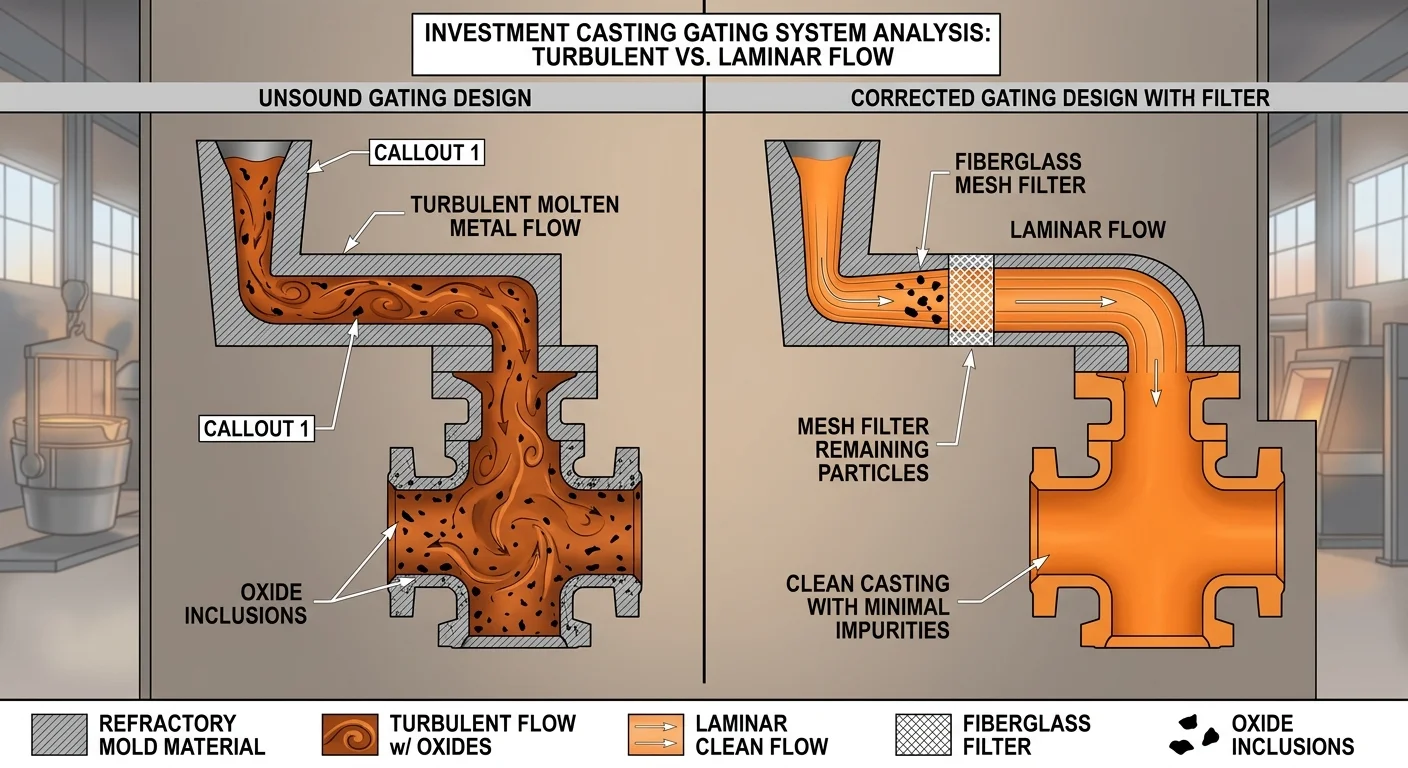
Push your mesh filter too far from the mold cavity — past 15 cm from the runner junction — and the filtering work means nothing. Velocity climbs back up. Flow turns turbulent. The metal picks up oxides and inclusions all over again before it reaches the cavity. It’s as if the filter was never there.
Industry gating studies put the non-fill defect rate at 20–30% for misplaced filters. Good placement drops that number below 5%. That gap comes down to one thing: position.
Aluminum die casting data backs this up. Misplaced filters tie directly to a 25% rise in inclusions and an 18% non-fill rate.
Fix it in four steps:
-
Measure from sprue exit to cavity — keep filter placement under 10 cm
-
Move cup filters to the runner inlet, not upstream near the sprue exit
-
Keep post-filter pour velocity below 1.5 m/s
-
Run a flow simulation. Target a Reynolds number below 2000 to confirm laminar conditions
The filter does its job. Then distance undoes it.
Mistake #2: Choosing Filter Shape and Material Without Defining Your Application Goal First
Most foundries pick their mesh filters the same way they pick consumables — by habit, by price, or by what the last supplier sent over.
That’s the mistake.
A flat fiberglass mesh filter dropped into a contoured runner system won’t seal well. Gaps form at the edges. Metal skips past the filtration zone. You get the pressure drop but none of the protection — the worst trade in casting.
Shape and material are not default choices you swap around freely. Each one needs to follow a clear application goal:
-
Primary goal: particle capture → go with finer mesh density, tighter weave, and smaller aperture size
-
Primary goal: flow rate control → match your filter geometry to your runner cross-section. Don’t restrict fill velocity past 1.5 m/s
-
Primary goal: thermal stability → fiberglass mesh filters have firm limits. Push past those limits and you lose filtration efficiency before the cavity even fills
The fix is simple — ask one question before you order:
What is this filter supposed to do in this specific pour?
Answer that first. Then pick the shape. Then pick the material. Do it the other way around — choosing the filter before setting the goal — and you end up with the right product solving the wrong problem.
Mistake #3: Assuming Early Success Means Your Filter Setup Is Permanent
Ten clean pours in a row will convince you that you’ve solved something. You haven’t. You’ve just been lucky long enough to stop paying attention.
This is where mesh filters start failing foundries that should know better. It happens without warning.
Your alloy temperature shifts. Batch size changes. Production cycles speed up. Each of these variables puts different stress on the same filter configuration you set up three months ago — the one that “worked.” The filter won’t alert you. The results will, in the form of unexpected inclusions and scrap rates that don’t add up.
What happens over time:
-
Thermal cycling breaks down fiberglass mesh filters bit by bit — efficiency drops before any defects show up
-
Process changes make your original setup conditions no longer valid
-
A configuration built for one alloy temperature will underperform at another
Success in the short term isn’t confirmation. It’s a baseline — and baselines need re-evaluation.
Set a review trigger, not just a replacement schedule. Alloy, batch size, or cycle frequency changes? Treat your filter setup as unvalidated until you’ve tested it against the new conditions.
Mistake #4: Using Inadequate Mesh Precision for the Particle Size You’re Filtering
Most foundries never take time to understand the relationship between mesh number and particle size. That gap shows up straight in casting quality.
Here’s the core problem: a 40 mesh filter passes particles up to 400 µm. A 100 mesh filter stops anything above 149 µm. A 200 mesh filter catches particles as fine as 74 µm. These numbers are not swappable. Use a 40 mesh filter where you need 100 mesh precision, and inclusions pass right through. They’re smaller than the openings. The filter never sees them. Your casting pays the price.
The selection logic is simple:
-
Finer particles require higher mesh numbers — match the filter to your actual target particle size, not your preferred flow rate
-
Wire thickness matters too — thicker wire cuts down open area even at the same mesh number. This shifts filtration performance without any visible change to the filter itself
-
Going too fine creates its own problems — higher mesh numbers restrict flow and clog faster. This gets worse under high-volume or thick, viscous conditions
Three steps to get mesh precision right:
-
Find the smallest particle size your process needs to capture
-
Pick your mesh number to match that size — then check that flow rate stays workable
-
Don’t overload the filter — too much material blocks openings and pushes filtration coarser than your mesh number is rated for
Wrong mesh precision doesn’t fail with a bang. It fails one inclusion at a time, and you won’t notice until the damage is done.
Mistake #5: Relying on Filters to Compensate for a Badly Designed Gating System
A filter is not a gating system. Treating it like one is how foundries end up confused about why their scrap rate won’t budge.
The gating system controls what happens to metal before it reaches the filter. Sprue geometry, runner dimensions, gate velocity — these decide whether flow arrives smooth or turbulent. A bad design creates turbulence upstream. At that point, the metal is already reacting with air and forming oxides. That happens long before it ever touches the mesh filter. By the time filtration starts, the damage is already done.
Filters cannot undo turbulence. They catch what turbulence leaves behind. Nothing more.
These are two separate problems. Each needs a different fix:
-
Turbulent flow upstream → fix the gating design. Shorten the flow path. Resize runner cross-sections. Keep gate velocity below 1.5 m/s.
-
Inclusions and oxides passing through → add mesh filters as a secondary layer. Place them in the right position.
The defect data is clear on what to fix first. Porosity from hydrogen entrapment comes from turbulent flow — not a filtration failure. Cold shuts and misruns point to slow fill and metal solidifying too early. Mesh filters don’t fix either of those root causes.
Gating design is the primary control. Fiberglass mesh filters are the secondary one. Flip that order and you’re pouring money into filtration. Meanwhile, the real problem keeps running unchecked — every single pour.
Mistake #6: Equating Higher Filter Weight with Better Filtration Performance
Weight measures mass. That’s all. It tells you nothing about what a mesh filter does to your metal.
This mistake is common — more common than most foundries expect. A heavier filter feels solid. It looks capable. So foundries assume more media density means better filtration. That logic is wrong — and it’s costing people good castings.
Here’s what filter weight reflects: media density and volume. Full stop. Pore uniformity? Not covered. Thermal resistance? Not covered. Compatibility with your flow rate? Also not covered. These are the variables that determine filtration efficiency — and weight says nothing about any of them.
The real danger is over-density. Push past 500 g/m² and you’ll see a 15–25% flow drop — with zero efficiency gain. Over-dense mesh filters create channeling, uneven filtration, and pressure loss above 20–50% in stacked configurations. Lifespan drops 2–3x faster than the rated value.
Select on these variables instead:
-
Pore uniformity: Target ±5–10% variation. Go above 15% and bypass opens up — up to 20% of particles pass through unfiltered
-
Open area: Keep coating density at 20–40%. Cross 50% solids and you block 10–20% of flow velocity
-
Thermal rating: Match your alloy melt point within ±50°C. Miss by more than 100°C and the filter fails within 5–10 cycles
-
Flow benchmark: Target 5–20 GPM/ft²; validate with a beta ratio above 75 at 10 µm
Heavier isn’t better. Matched is better.
Mistake #7: Purchasing Low-Quality or Unverified Fiberglass Mesh Material
The filter looks fine. It ships fast. It costs less. And it will destroy your castings from the inside out.
Cheap, unverified fiberglass mesh skips two things that matter most: alkali-resistant (AR) coating and tensile strength. No AR coating means the mesh breaks down in cement-based environments. Low tensile strength means stress doesn’t spread — it builds up in one spot. Cracks come next. Then delamination. Then full structural failure — all traced back to a purchase no one checked.
What certified mesh requires:
– AR-coating that meets ETAG 004 standards
– Tensile strength specs listed in a technical data sheet
– Density matched to your job — lightweight mesh doesn’t belong in heavy-duty work
– UV resistance for any outdoor use
Before you approve a supplier, check:
– Certification documents (ETAG 004, AR-coating compliance)
– Minimum 10 cm overlap between strips
– Physical inspection for damage before use
|
Aspect |
Low-Quality |
Certified |
|---|---|---|
|
Coating |
None or standard |
AR-coated (ETAG 004) |
|
Failure risk |
Early cracks, delamination |
Long-term structural integrity |
|
Application fit |
Mismatched density |
Matched to load requirements |
Price is not a specification. Use it as one, and the mesh fails first — everything else follows.
Mistake #8: Skipping Configuration Testing Before Full Production Runs
Every untested configuration change is a live bet against your production run.
Foundries do this all the time. A new alloy comes in. Mesh filters get swapped. Someone adjusts the flow rate. Then the line goes straight to full production — because the last setup worked, and this one looks close enough.
It isn’t close enough. It’s untested.
What skipping validation costs you:
-
Hidden constraint violations that don’t show up until metal is already in the mold
-
Flow rate drift that goes unnoticed until scrap starts stacking up
-
Configuration failures that wipe out an entire production run — hours of output, gone
The fix: run a structured 3–5 run validation sequence before going to full volume. Test your mesh filter configuration under varied load conditions. Measure throughput against your baseline. Check for pressure irregularities and fill inconsistencies across each trial run.
Then document it. Log your filter-configuration pairings — what failed, what held. That record builds institutional knowledge. It stops the next team from making the same bet.
A configuration that hasn’t been tested hasn’t been approved. It’s just been assumed.
Mistake #9: Neglecting Metal Preparation Before Filtration
Clean metal makes a filter work. Dirty metal makes a filter fail — and fail fast.
Filtration is the last line of defense. It was never built to be the sole defense. Degassing, flux treatment, and slag skimming must happen before metal touches your mesh filters. Skip those steps, and you’re not filtering a melt. You’re trying to hold back a flood with a screen door.
The numbers are brutal. Underprepared melt raises non-metallic inclusions by 20–50%. That load speeds up clogging and cuts filter life by 3–5x. Push past the filter’s capacity and inclusions break through. Once breakthrough exceeds 10% of surface area, defect rates spike right after.
Clogging makes it worse. Poor melt prep causes pressure drop 30–40% faster than normal. Unskimmed slag alone doubles or triples inclusion count after filtration. Drag-in particles above 5 µm cut bath life by 40%.
Minimum prep benchmarks before filtration:
-
Aluminum: Degas to below 0.2 cm³/100g H₂, then flux treat
-
Steel/Superalloys: Skim all visible slag. Confirm soluble iron stays below Fe²⁺ 100 mg/L. This stops iron oxide from forming — which can inflate inclusion readings by 15–25%
The mesh filter is not a substitute for preparation. It’s the final checkpoint. Checkpoints work best when the process upstream is already under control.
Mistake #10: Improper Filter Handling, Layering, or Installation Setup
Foundries spend weeks chasing metallurgical perfection — then lose it in thirty seconds of careless installation.
That’s the bitter irony of bad filter handling. The mesh filter is the right spec, the right size, the right position. Then someone forces it in wrong. They reverse the inlet and outlet. They over-tighten the housing until the threads strip. The casting defects that follow get blamed on the filter. That blame is misplaced.
These failures come from the installer. Every single one is preventable.
Here’s where the damage shows up:
-
Reversed inlet/outlet orientation — Flow runs the wrong way. You get pressure loss and leaks. This isn’t a minor issue. It’s a full breakdown of your filtration setup.
-
Backwards filter placement — Airflow drops. The system strains. Debris builds up against the wrong face of the mesh.
-
Over-tightened housings — Plastic cracks. Threads strip. Seating integrity fails. A pipe wrench on a filter housing will destroy the seal. Every time.
-
Neglected O-rings — They degrade quietly until they start leaking. Inspect at every change. Lubricate with food-grade silicone. Replace anything flattened or brittle.
Install it right, every time:
-
Thread the housing by hand first. Feel resistance? Stop and realign before going further.
-
Tighten to a snug fit. Any wrench adjustment should be minimal — not forceful.
-
Clean and inspect the O-ring at every filter change. No exceptions.
-
Check inlet/outlet orientation before the housing closes. Verify it visually.
A fiberglass mesh filter installed backwards filters nothing. It just sits in your gating system taking up space while your scrap rate climbs.
How to Build a Zero-Mistake Fiberglass Filter Protocol for Your Foundry
Ten mistakes. One through-line: every single one was preventable at the protocol level.
This is where it ends — not with more warnings, but with a system you can run before every pour.
Pre-Pour Audit Checklist
Work through this before metal moves:
-
Filter integrity — Check for uniform coating, no lumps or voids. Pull test reports that confirm EN ISO 2078 weave density and less than 5% weight loss at 300°C over two hours
-
Fit and alignment — Cut sheets to your runner dimensions (150–300mm). Seat them snug. Let sand support the edges. Gaps mean bypass — and bypass means the filter never did its job
-
Spec match — Confirm your alloy temperature against the filter rating. Use resin-coated mesh for anything above 400°C. Match porosity to your target particle size, not your preferred flow rate
-
Positioning — Place filters high in the mold, post-sprue, pre-gate. Replace trough rolls every 5–8 molds. Don’t wait until someone notices
-
Gating geometry — Increase runner cross-section in 10% steps after the filter toward the ingates. This keeps priming complete and cuts turbulence before it starts
Calling In Outside Expertise
Some problems go beyond internal troubleshooting. Three triggers that signal it’s time:
-
Defects stay after filter replacement and gating corrections
-
Inclusions are getting finer — not larger — after filtration
-
You’re changing alloy, temperature range, or geometry and have no validated spec for the new conditions
Send your operational parameters — temperature, flow rate, impurity size, alloy type, runner geometry — to your mesh filter supplier. Ask for a custom specification. Get third-party lab verification to confirm coating uniformity and fiber integrity before full production starts again.
The protocol isn’t complex. It’s just consistent. Run it every time, and the mistakes in this guide stay right where they belong — on the page, not in your castings.
Selecting the Right Fiberglass Mesh Filter: Key Specifications Explained
Specification mismatches don’t announce themselves. They build up — one compromised pour at a time — until your scrap rate tells the story your filter selection should have told you from the start.
Four specifications drive every filter decision worth making:
-
Mesh weight — Controls tensile strength and rigidity. Low elongation (around 3%) means the filter absorbs impact energy as molten metal hits it. It holds its shape instead of deforming under pressure.
-
Pore size — Openings range from 0.8×0.8mm to 3.0mm. These filters work by surface filtration — not depth. Porosity runs 50–60%. That number feeds straight into your casting system area calculation.
-
Coating type — The FM-07-ST series carries a high-temperature coating rated for 1500–1700°C steel pours. That coating isn’t cosmetic. It stops thermal shock from breaking down the filter mid-pour.
-
Fiber composition — High-silica glass fiber (SiO₂ at 58–65%), loss on ignition ≤3%, gas emission ≤30cm³/g. These aren’t marketing numbers. They define how clean your melt environment stays during filtration.
Match your series to your metal:
|
Series |
Metal |
Temp Range |
|---|---|---|
|
FM-07-AL |
Aluminum alloys |
700–800°C |
|
FM-07-FE |
Cast iron, copper |
1300–1450°C |
|
FM-07-ST |
Steel alloys |
1500–1700°C |
|
FM-07-CU |
Copper alloys |
1000–1200°C |
Standard SKUs don’t cover every condition. Extreme temperatures, non-standard porosity, unusual inclusion targets — these need a different approach. Custom mesh filters with modified structures and pre-formed caps exist for those cases. Don’t force a standard spec into a non-standard application.
Conclusion
Every defect that slips past your filtration setup has an origin story. Most of them start long before the metal ever touches the filter.
The ten mistakes covered here share a common thread: they’re not random bad luck. They’re predictable, repeatable failures. Each one traces back to skipped steps, wrong assumptions, or filters pushed into roles they were never built for.
Fix the placement. Match the mesh precision to your actual particle challenge. Stop treating early wins as proof that your process is solid. And never — not once — let a filter stand in for a gating system that needs real engineering.
Your mesh filters are only as effective as the protocol around them. Build that protocol with clear intent. Test it against real results. Revisit it any time your alloy, geometry, or pour conditions shift.
The foundries producing clean castings aren’t running on better luck. They run on better discipline.
Start with one mistake from this list. Fix it fully. Then move to the next.