Scrap rates don’t lie.
Yield consistency starts slipping, and most foundries chase the obvious culprits — pour temperature, alloy chemistry, mold design. But the real problem sits in the gating system. It’s hiding in plain sight.
The top 3 mistakes foundries make when choosing casting filters have less to do with what filters do. They’re about how filters get selected in the first place.
Wrong material. Wrong placement. Wrong assumption that one filter covers every application. Each mistake feeds the next.
Mistake 1: Treating Casting Filters as Interchangeable
Here’s a number worth sitting with: 35% of yield inconsistency in foundry operations traces to filter-alloy mismatch.
Not process variation. Not operator error. A filter choice made upstream — often by someone working from a purchase order rather than a spec sheet.
The “one filter fits all” assumption doesn’t announce itself as a mistake. It hides inside a 28% scrap rate. Or a gas porosity reading that won’t cooperate no matter how many times you adjust pour temperature. The filter was wrong from the start. Everything downstream paid for it.
The Physics of Why PPI Selection Matters
Filters aren’t passive screens. They’re engineered flow-management systems. The pores per inch (PPI) rating has to match the alloy’s viscosity at pour temperature — not just the general melt category.
A mismatch causes inclusion capture to fall off fast:
-
A generic 30 PPI filter on an A356 aluminum alloy pour leaves inclusions larger than 20–50 microns moving through the system. Gas porosity defects climb 20–25% above baseline.
-
Swap in a spec-matched 45 PPI zirconia filter for the same alloy. Porosity drops to below 2%. The generic alternative sits at 10%. That gap doesn’t narrow — it compounds across every batch.
Viscosity drives everything here. High-viscosity alloys need 50–65 PPI. Low-viscosity alloys need 80+ PPI. Run the wrong grade and the flow rate drops 10–15%. Turbulence increases. Oxidation does the rest — costing another 12% in yield before the casting ever reaches inspection.
The Steel-in-Aluminum Problem (And What It Costs)
Cross-material substitution is where the numbers get bad — fast.
Steel foam filters — rated 10–20 PPI — used in an aluminum pour push bifilm defects up by 40%. Scrap climbs to 28%. Foundries using alloy-matched filters on the same aluminum applications hold scrap to 5–8%.
That’s not a small difference. On a 500kg melt batch, moving from a generic filter to a spec-matched one has pushed first-pass yield from 72% to 91% in documented foundry trials.
|
Filter Type |
Alloy Match |
Yield Impact |
Defect Reduction |
|---|---|---|---|
|
Generic 30 PPI |
Any |
−25% yield |
10–15% porosity |
|
Specific 50 PPI |
A356 Aluminum |
Baseline |
90% inclusion removal |
|
Specific 20 PPI |
Ductile Iron |
+18% yield |
<5% slag defects |
How to Stop Guessing and Start Matching
Three steps. No ambiguity.
-
Measure alloy viscosity at pour temperature. For A380 at 680°C, target 4–6 cP. Below 4 cP: select 65+ PPI. Between 6–8 cP: use 45 PPI.
-
Calculate required filter area using flow rate. Filter area (cm²) = (flow rate L/min × 60) ÷ (0.5–1 m/s velocity). A mismatch here creates an 18% pressure drop. That cascades into a 22% yield loss.
-
Set an inclusion capture benchmark before you approve any filter. Target >95% removal of 10–30 micron oxides. Generic filters average 70%. Spec-matched filters reach 98%. A supplier who can’t provide capture rate data has already given you the answer.
The filter isn’t a consumable afterthought. It’s a process variable — and it behaves like one whether you’re managing it or not.
Mistake 2: Getting Filter Placement Wrong
Filter placement doesn’t get a meeting. It gets a habit.
Someone decided where the filter goes — years ago, based on what fit the gating geometry at the time. That decision hardened. Now it runs on autopilot, pour after pour, while defect rates pile up in the background.
The distance between your filter and the mold cavity isn’t a secondary variable. It is the variable. Most foundries have never run a single controlled test to confirm their current placement is close to optimal.
Why Distance Changes Everything Downstream
Here’s the mechanical reality: a filter placed too far from the mold cavity loses its functional advantage before the metal arrives.
The problem isn’t filtration failure at the filter itself. The metal passes through well enough. But over the travel distance — every extra inch between filter and cavity — two things happen at once:
-
Metal temperature drops. Cooling starts the moment filtered metal exits the filter face. By the time it reaches the cavity, viscosity has shifted. Flow dynamics change. The clean metal you paid for with the right filter spec starts behaving like unfiltered metal moving too slow.
-
Recontamination starts. Turbulence in the runner between filter and mold picks up oxides from the runner walls. The filtration work done upstream gets undone in the last few inches of the gating system.
Foundries placing filters more than 4 inches from the mold cavity see casting quality drop 15–30% compared to tighter placements. That range isn’t small. The low end is survivable. The high end eats your scrap budget before you’ve found the cause.
The Positioning Window That Works
The functional placement range for Investment casting ceramic foam and fiberglass Mesh filters is 1 to 3 inches from the mold cavity. Inside that window, you get the balance that makes filtration pay off:
-
Metal velocity stays high enough to maintain a controlled, non-turbulent fill
-
Temperature retention keeps viscosity inside the range your filter PPI was selected for
-
The runner gap is short enough that recontamination risk stays low
Move past 3 inches and the window closes. Not in a dramatic way — which is exactly why it goes undetected. Defect rates creep up in small steps. Each pour looks marginal, not broken. The full picture only shows up in monthly yield reports, where it gets blamed on something else.
The Test Most Foundries Skip
To test filter placement, run three controlled pours at different filter positions — 1 inch, 2.5 inches, and 4+ inches — using identical alloy, temperature, and gating geometry. Track four variables:
-
Inclusion count per casting (cross-section analysis)
-
Surface finish rating at the cavity wall
-
Fill time variation across the position range
-
Porosity reading at standard inspection depth
Most foundries skip this test because the setup takes half a shift. The cost of skipping it — letting placement error compound across every production run — runs far higher than half a shift.
Your current placement was inherited, not tested. You don’t know what it’s costing you. That’s the real problem with Mistake #2. It’s not ignorance of the principle. It’s the confidence that comes from never having checked.

Mistake 3: Choosing Filter Material Based on Price
The purchase order wins. Every time.
Someone in procurement spots two filters — same dimensions, same PPI rating, different price tags. The cheaper one gets circled. The logic seems solid: filters are consumables. Consumables are cost centers. Cost centers get trimmed.
But that purchase order never shows what happens inside the Gating System at 700°C.
What “Cheaper” Buys You
Material incompatibility doesn’t fail with a bang. It fails in silence — pour after pour — in ways that look like normal process variation. Until the pattern gets too obvious to explain away.
Here’s what happens at the mechanical level. You pick a filter based on price, not thermal and chemical fit:
-
Pores swell and close off. Flow rate drops. In some cases, the filter blocks mid-pour. The metal goes where it shouldn’t.
-
Aggressive alloy chemistry dissolves the filter material. Not degrades — dissolves. You end up pushing filter particles straight into the melt you just paid to clean.
-
Seals fail. Unfiltered metal skips around the filter. The filter sits there. It does nothing.
None of these problems show up on the casting floor. They surface later — in porosity readings, in inspection rejects, in a scrap rate that keeps climbing with no clear cause in sight.
The Temperature Ceiling Problem
Every filter material has a thermal limit. Push past it and the material doesn’t just lose performance — it breaks down in ways that contaminate the pour.
These limits matter more than most foundries admit:
-
Polypropylene (PP): Tops out at 93°C. Good chemical resistance, but poor heat tolerance. Fine for water-based pre-filtration and short-exposure acid or alkaline environments. Not for high-temperature casting.
-
PTFE: Holds up to 260°C. The top choice for extreme chemical environments and long-duration high-heat exposure. Heavier and pricier — but it performs where others break down.
-
Standard polymers: Stable to around 120°C. Metal alloy casting runs above 500°C. The gap speaks for itself.
-
Polypropylene vs. polyester cartridges: Different heat and chemical tolerance profiles. Not interchangeable — even when the dimensions look identical.
Picking a PP filter for a high-temperature aluminum pour isn’t a cost-saving move. It’s a process failure with a paper trail.
How to Select by Compatibility, Not Cost
Four steps. Clear. Non-negotiable.
-
Start with your chemical environment. Acidic, alkaline, solvent-bearing, oxidizing — your alloy chemistry sets the material constraint. Price comes after that, not before.
-
Check both continuous operating temp and peak temp. Peak temp matters more. A filter rated for 200°C average but failing at 280°C peak has already failed your process.
-
Factor in exposure time. Short-batch runs can handle lower-grade materials like PP. Continuous high-temperature pours need PTFE or something equivalent. Using batch-grade material in a continuous process is still a price mistake — you pay with downtime instead of invoice costs.
-
Test before you commit. Wet the filter with your actual process fluid. Use chemical compatibility charts as a real decision tool, not a box to tick. Check every component: filter media, seals, and adhesives. Fluid mixtures and thermal cycles need application-specific testing — generic ratings won’t cut it.
A practical compatibility reference, mapped to cost:
|
Material |
Cost Level |
Key Strength |
Hard Limit |
Best Use Case |
|---|---|---|---|---|
|
PP |
Low |
Short-exposure chemical resistance |
Max 93°C |
Batch water filtration |
|
Polyester |
Low–Med |
General use |
Lower chemical tolerance than PP |
Non-extreme liquid environments |
|
PTFE |
High |
260°C, extreme chemical stability |
Higher cost, heavier weight |
Continuous harsh-environment pours |
|
PES |
Med–High |
Sterile filtration performance |
Solute-specific constraints |
Pharmaceutical / aqueous applications |
The compatibility chart isn’t the costly option. Replacing scrap from an incompatible filter is.
Price-based filter selection ranks among the quietest mistakes foundries make with casting filters — and the hardest to trace after the damage sets in. The filter that caused the problem is gone by the time the casting hits inspection. All you’re left with is the defect and a process team chasing the wrong cause.
How to Audit Your Current Filter Selection Process
Three mistakes. Three compounding costs. One process gap connecting all of them: nobody has audited how the filter selection decision gets made.
The audit isn’t complicated. It has to be systematic, though. Otherwise you’re just confirming what you already believe — not finding where the process is breaking down.
Here’s a practical 3-point checklist to run against your current setup.
Pull Your Last 20–30 Filter Selections and Score Them Against Outcomes
Not against what the supplier spec sheet promised. Score against real measured results — scrap rate, inclusion count, yield per batch.
For each selection, ask one question: did this filter hit >90% particle capture efficiency at the specified pore size? That’s your baseline threshold. A β-ratio of 10 means 100 particles go in, 10 come out — 90% removal. A β-ratio of 100 means one comes out. Miss β-10 at minimum, and you’re approving filters without knowing what they do.
Map the selections to outcomes. A pattern will emerge. Specific filter types underperform on repeat. Specific alloy pairings drive scrap up regardless of other variables. That pattern is your audit finding.
Run Three Validation Tests on Any Filter Before Approval
One pass isn’t enough. Run in triplicate.
-
Efficiency test: Filter a 100% working standard. Compare the unfiltered response against the filtered one. Accept nothing below 95% recovery. Ultrasonicate samples at 0, 5, and 10 minutes to stress-test performance under real flow conditions.
-
Adsorption test: Measure blank solutions after filtration. A filter pulling target material out of solution isn’t cleaning your process — it’s contaminating it.
-
Leachability test: Analyze filtered standards right away, then again after standing. Any drift points to filter material shedding into your melt.
Depth filters should hit >99.99% absolute removal. A supplier quoting 90% at 5 microns as their headline spec is using that number to hide a very large gap.
Reconcile Patterns, Update Your Qualifiers, Rerun Every 30 Days
A one-time audit fixes last quarter’s problem. A recurring audit stops next quarter’s from forming.
After each review cycle, identify your drag patterns. Look for filter types driving double the defect rate on a regular basis. Flag placement decisions that never got tested. Catch material substitutions chosen on price that fouled downstream yields without anyone noticing. Update your qualification criteria based on what the data shows — not what the original spec assumed.
Then rerun the loop in 30 days.
The benchmark to hold: filter efficiency >95%, β-ratio between 10 and 100 depending on application, material compatibility confirmed against both peak temperature and alloy chemistry — not just rated average conditions.
The top 3 mistakes foundries make choosing casting filters all leave fingerprints in this checklist. Wrong material shows up in efficiency scores. Wrong placement shows up in outcome variance. Wrong compatibility assumptions show up in leachability and adsorption results.
Run the checklist. The data tells you which mistake you’re living with.
Key Selection Factors Reference Table — Mesh Size, Flow Rate, and Material Decision Guide
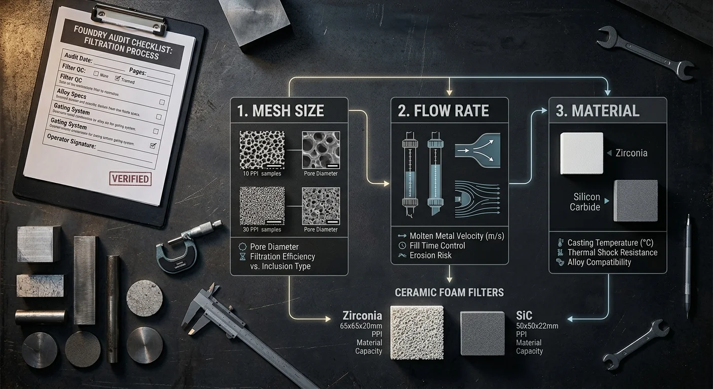
Three variables decide whether your filter works or fails: mesh size, flow rate, and material. Get one wrong and the other two won’t fix it.
This table takes the guesswork out.
Mesh Size and Practical Particle Capture
Theoretical mesh ratings don’t tell the full story. The number on the spec sheet is not what your process actually sees.
Take a 325-mesh filter. Its theoretical opening is 78.2 µm. The practical capture size is 44 µm. That gap is real, and it matters. Oxide inclusions in the 20–50 µm range fall right in between. Base your filter choice on practical particle size — not the theoretical figure.
|
Mesh Size |
Practical Opening (µm) |
Casting-Relevant Use |
|---|---|---|
|
100–200 |
149–74 µm |
Coarse slag, bulk inclusion removal |
|
270–325 |
53–44 µm |
General industrial aluminum, iron pours |
|
400–500 |
38–25 µm |
Fine oxide capture, surface-critical castings |
|
635–800 |
20–15 µm |
High-specification coatings, precision parts |
Flow Rate Trade-offs You Can’t Ignore
Finer mesh gives you better inclusion capture. It also reduces flow rate. That trade-off is fixed — it’s physics, not preference.
-
Coarse mesh (100–200): High flow, low pressure drop. Use it where throughput matters more than fine inclusion control.
-
Fine mesh (400–800): Lower flow, higher resistance. Your gating system must support it. Skip that step and backpressure builds — turbulence follows right after.
-
High-viscosity alloys need coarser openings. Push a high-viscosity melt through fine mesh and flow rate drops 10–15%. Worse, it brings back the turbulence you cleared out earlier in the process.
Material Decision: Environment Drives the Choice
|
Material |
Temperature Limit |
Best Condition |
|---|---|---|
|
Stainless Steel |
High |
Corrosive, high-heat pours |
|
Copper/Brass |
Moderate |
Non-corrosive, cost-sensitive applications |
|
Titanium |
Extreme |
Manufacturer-specified harsh environments |
|
Nylon/Polyester |
Low |
Chemical-specific, non-metal fluid applications |
Stainless steel covers most foundry demands. Titanium steps in where stainless falls short. Every other option is a trade-off — one you either choose with clear eyes or stumble into by default.
Five-step decision sequence:
1. Pin down your target particle size — use practical opening, not theoretical
2. Check required flow rate and how much pressure your system can handle
3. Match the mesh grade from the table above
4. Pick filter material based on pour temperature and alloy chemistry
5. Run a pressure drop test before you commit to full production volume
The table doesn’t decide for you. It just clears the fog so you can.
Conclusion
Most foundries don’t have a filter problem — they have a decision-making problem.
Treating filters as interchangeable commodities leads to trouble. Guessing at placement without testing makes it worse. Letting purchasing decisions ride on price alone? That’s not saving money. That’s building defects into every pour before the metal moves.
Foundries that hit yield targets aren’t running magic alloys or exotic equipment. They ask better questions before the pour — about compatibility, positioning, and what “good filtration” means for their specific process.
Run the 3-point audit. Pull out the selection table. Take an honest look at your current filter choices. Were they picked with purpose, or did they just carry over from old habits?
The top 3 mistakes foundries make when choosing casting filters are all fixable. But fixing them starts with admitting they exist.
Start with one pour. Change one variable. Measure what happens.
That’s not a small thing. In casting, that’s everything.