A single batch of defective Fiberglass mesh filters can ruin an entire pour, turning a routine casting run into scrap and rework. Most of these failures are preventable with a few minutes of inspection before a filter ever touches your gating system.
This guide outlines a practical, field-tested approach to Fiberglass filter mesh inspection. It catches the issues that matter, including uneven mesh count, hidden moisture damage, dimensional drift, and structural weak points that fail under molten metal flow pressure.
Whether you’re a QC engineer building an inspection SOP or a purchasing manager vetting a new supplier, you can apply this step-by-step checklist directly to your next incoming shipment without guesswork.
Why Pre-Use Fiberglass Mesh Filter Inspection Is Critical in Foundry Production
Defects caught after machining cost 3–5 times more than defects caught before pouring even starts. That gap separates a routine containment step from a full-blown quality escape that eats into margin, delivery schedules, and customer trust.
Filter inspection matters because the mesh either traps oxide, slag, sand, and refractory particles, or it lets them straight through. In one automotive-suspension foundry, tightening filtration practices and gating design dropped inclusion-related scrap from 4.0% to 1.5%, a 62.5% relative reduction. Across the broader industry, optimized casting filtration cuts rejection rates by 30–50% in operations where slag and oxide drive most defects.
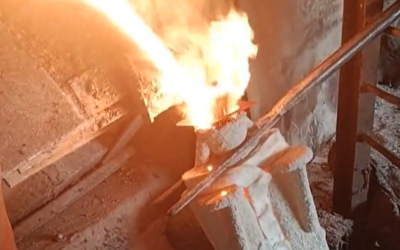
molten metal filtration leaves no room for shortcuts. A cracked coating or a compromised strand easily slips past a casual glance, but the mesh will break down once metal starts flowing through the Gating System. By then, the inclusion is already in the casting.
Step 1: Verify Documentation and Batch Traceability Before Inspection
Paperwork catches problems your eyes can’t. Before unboxing a single roll, match the purchase order against the packing list, supplier label, CoA, and inspection report line by line. The PO number, product model, roll or sheet count, quantity, and delivery date all need to line up.
Each roll or batch should carry a unique lot number that traces back to raw material heat numbers, production records, and test results. Broad labels like “304 stainless steel” or “200 mesh” are not enough for foundry filter quality control. You need the alloy grade, wire diameter, nominal mesh count, weave type, and tolerance spelled out.
Label Checklist:
– Lot/heat number
– Product model and PO number
– Alloy grade and standard (ASTM A580, EN 10270, or customer spec)
– Mesh count, nominal opening size, wire diameter, weave type
– Roll/sheet number, dimensions, net weight
– Production and inspection dates, packaged quantity
– Supplier quality release signature or e-approval
Never accept a generic material certificate. Ask for one tied directly to the specific heat number. A mismatch here is often the first sign of a batch that will fail once it meets molten metal flow.
Step 2: Check Packaging and Storage Conditions for Moisture Damage
Moisture ruins fiberglass mesh filters. It weakens the binder, distorts the weave, and leaves you with a filter that looks fine until molten metal hits it.
Inspect every container before opening for:
– Soft, sagging cartons or delaminated layers
– Bulging, wet spots, condensation, or mold odors
– Torn, punctured, or resealed packaging
– Crushed corners, tilted pallets, or permanent creases
Any of these signs means quarantining the batch.
Storage conditions require the same discipline. Keep warehouse humidity at or below 65% RH and log temperatures around the clock. Pallets should sit off the floor, away from exterior doors, walls, and HVAC vents where condensation risk spikes.
If you spot mold, discoloration, or caking, isolate the lot, tag it, take photos, and route it to QC before it ever touches your gating system.
Step 3: Perform Visual Inspection Under Proper Lighting Conditions
Lighting makes or breaks a visual inspection. Harsh glare or dim corners hide the defects that cause casting filters to break downstream. Set up flicker-free, diffused white LED lighting at 4,000–6,500K color temperature, with at least 100 foot-candles (roughly 1,100 lux) across the work surface. Keep the area free of glare hotspots.
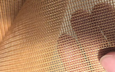
Prep and Front-Side Scan: – Lay the Fiberglass mesh cloth filter flat on a clean, high-contrast table without folds, overlaps, or tension – Keep a magnifier, steel ruler, lint-free cloth, and defect log ready – Scan left to right and top to bottom from 30–50 cm away – Check mesh continuity, warp and weft integrity, edges, seams, and resin coating uniformity
Back-Side and Backlight Check:
Flip the filter without dragging or bending it. Inspect it with backlighting next, which catches through-holes, cracks, and clogged mesh that front-light scans miss.
|
Defect |
Reject If |
|---|---|
|
Broken strands |
Form continuous openings or enlarge mesh in the filtration zone |
|
Cracks |
Penetrate through or run near seams/edges |
|
Tears |
Material missing, tip points present |
|
Resin buildup |
Blocks pores or flakes under pressure |
|
Rust/oil spots |
Won’t wipe clean with lint-free cloth |
Log the type, size, location, and a photo for every defect before deciding whether to pass, rework, or reject the part.
Step 4: Measure Mesh Uniformity and Weave Consistency
Visual scanning catches obvious surface flaws, but it misses a drifting mesh count or a weave losing grip across the roll. This step replaces guesswork with hard numbers.
Sampling Protocol:
Measure nine zones per roll: left, center, and right positions at the head, middle, and tail. Record warp and weft openings at each spot against a black background for clear contrast, using a calibrated steel ruler, count glass, or image measurement system. For openings between 1–16 mm, measure 10 consecutive pitches. For finer 0.1–1 mm mesh, measure 20 pitches and average the result.
Key Fields to Log:
– Mesh count (warp × weft, such as 32 × 32, rather than a single nominal number)
– Strand diameter at 0.001 mm resolution
– Opening width: w = 25.4/M − d
– Open area: Ao = (w/(w+d))² × 100%
Acceptance Limits: – Mesh count deviation: ±2% – Opening size: ±5% average, ±10% single-point – Open area: ±5 percentage points (±3 for precision aluminum filtration mesh) – Warp/weft skew: ≤4°
Flag any pore exceeding the max diameter by 10%, two adjacent oversized pores, or visible yarn breaks, double threads, and misweaves. These flaws cause casting filters to fail downstream, so do not average them away. Isolate and photograph every out-of-spec zone before disposition.
Step 5: Check Dimensional Tolerance Against Approved Specifications
An oversized filter won’t seat properly in the cavity. It scrapes sand loose, drops particles into the melt, and causes the exact inclusion defects it was supposed to prevent.
Pull the approved drawing and balloon every dimension, covering length, width, diameter, thickness, geometric tolerance, and revision level. Measure length and width at a minimum of three points along each axis. Check the diameter across two perpendicular planes, increasing to four if you suspect distortion. For thickness, take readings at the center and four points around the perimeter, then use the minimum reading for lower-limit acceptance.
Typical foundry filter dimensional inspection limits:
– Below 100 mm: −1.5 to 0 mm
– Above 100 mm: −2.0 to 0 mm
If the contract calls for tighter tolerances than the supplier standard, the contract wins. Never average conflicting specs.
Step 6: Test Mechanical Integrity and Compressive Strength
A filter that looks perfect under inspection lights can still crumble once metal pressure hits it. Mechanical testing comes last, after every visual and dimensional check has passed.
Hand-Check for Hidden Weak Points:
Put on gloves and run your fingers along the edges, corners, and pore walls. Do not scrape, tap, or twist. Focus on the four corners of the outer frame, thin edges, pore openings, and where support ribs cross. Reject any piece with through-cracks, chipped corners, loose particles, or visible delamination. Lift and tilt the filter slowly. If you hear rattling, see flaking, or notice edges shedding material, fail the batch.
This hand check is purely qualitative. It catches shipping damage and loose debris, but it will not replace destructive testing to prevent filter breakage during casting.
Compressive Strength Testing:
Run single-axis compression tests per ASTM C133 or an equivalent standard on a universal testing machine. This confirms the filter can handle static metal head, clamping force, and pour impact. Published cold compressive strengths range from 0.5 to 2.5 MPa, depending on material and density.
Reference Benchmarks: – General Ceramic foam Filters: 0.8–1.5 MPa – Higher-strength specs: 1.0–2.0 MPa – Reinforced or high-density products: 1.2–2.0 MPa – Typical product data sheet values: ~0.9 MPa compressive, ~0.8 MPa flexural
Set ≥1.0 MPa as your room-temperature baseline for incoming inspection. If you run deep filter boxes, high metal heads, or fast flow rates, raise that target to 1.5 MPa or higher. One Alumina foam specification for aluminum filtration mesh lists ≥1.0 MPa at room temperature, recommending a sampling rate of one piece per 50.
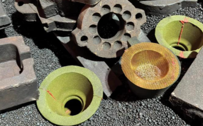
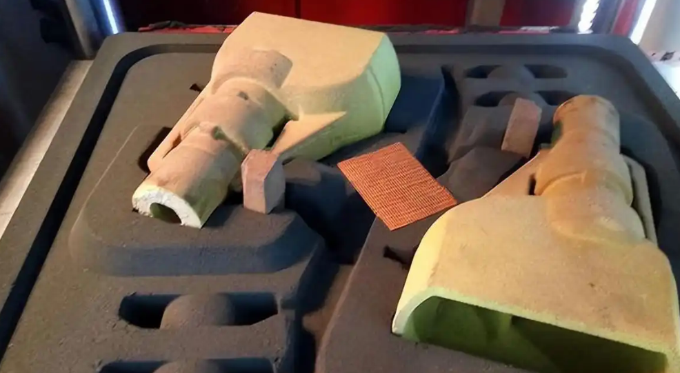
Material-Specific Judgment Calls: – Alumina: foam filters usually start at ≥1.0 MPa, with reinforced or high-density options reaching 1.2–2.0 MPa. This is the standard choice for aluminum filtration mesh. – Silicon carbide: These suit higher temperatures and severe thermal shock. Because strength depends on porosity, PPI rating, coating, and support structure, ask your supplier for batch-specific ASTM C133 data instead of relying on alumina numbers. – Zirconia: These handle higher-temperature alloys but cost more. Verify the hot modulus of rupture and residual strength after thermal cycling before accepting a shipment. – Fiber or metal mesh: Do not evaluate mesh filters on compressive strength alone. Set separate requirements for tensile strength, edge tear resistance, mesh integrity, and coating adhesion. Cut edges must show zero loose fibers.
Tensile Testing — When It Applies: Tensile testing applies to filters with fiber reinforcement, wire mesh, or structural backing, where handling and clamping stresses pull on the material. Brittle ceramic foams do not yield useful tensile data compared to compression or flexural tests. If a supplier cannot provide tensile specs for reinforced media, make edge integrity, flexural fracture, and compression testing your minimum release criteria.
Hot Integrity for Demanding Applications:
If your setup involves deep boxes, high metal head, or fast pour velocities, validate the filter with a hot trial pour. Published hot modulus of rupture values sit between 0.3 and 1.5 MPa, well below room-temperature compression figures. Never assume cold-test data holds up once molten metal hits the filter.
Assembly and Thermal Handling Rules
Installation requirements: – Full-perimeter support only. Point contact concentrates stress, which breaks the filter during the pour. – Eliminate bypass gaps between the filter box, runner plate, and mesh. A snug seal reduces edge stress and keeps molten metal from slipping around the filter. – Never expose a cold filter directly to molten metal. Follow the supplier’s preheat curve to drive out moisture. Thermal shock on a cold or damp filter will crack it on contact.
Three-stage inspection log: Photograph and log edge condition at three points: after handling, after assembly, and after the trial pour. If a filter fails downstream, this record shows where the damage started.
Release Criteria Checklist
-
Visual: Zero through-cracks, chipped corners, delamination, or loose particles
-
Hand-check: No flaking, rattling, or crumbling edges under gentle handling
-
Cold compression: ≥1.0 MPa for standard applications; ≥1.5 MPa for high metal head or high pour impacts
-
Sampling rate: At least one piece per batch, or one per 50 pieces if following supplier protocol. Expand sampling and quarantine the lot if any piece fails
-
Metal head check: For deep filter boxes with more than 200 mm of metal head, verify that the supplier’s strength rating covers your static pressure and clamping load
Skipping these checks to save five minutes on the floor turns a $2 filter into a $2,000 scrap casting.
Step 7: Detect Moisture and Contamination Before Installation
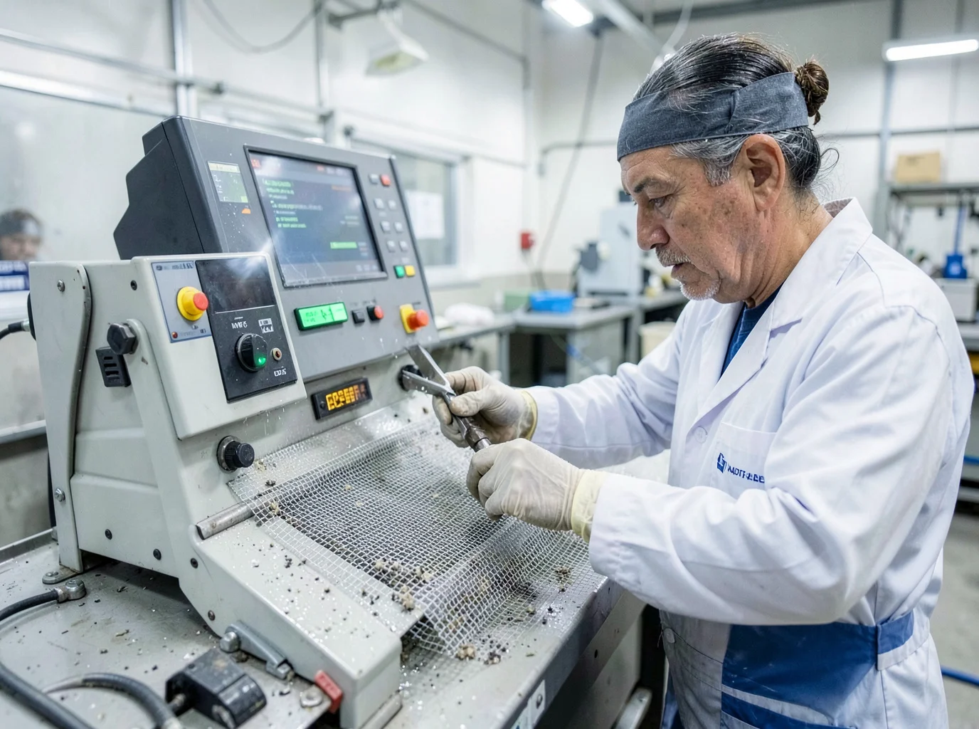
A filter that passes every visual and mechanical check can still fail if moisture or debris hides inside the weave. This step pairs a lab-grade moisture test with a surface contamination scan to catch what hand checks miss.
Moisture Testing (ASTM D2654):
Pull a 5g sample from multiple spots in a sealed container. Weigh it wet on an analytical balance (0.001g resolution), then dry it at 105±2°C in a forced-air oven. Recheck every 2 hours until the mass change drops below 0.01% between readings. Test three parallel samples and report the average, max, and min. Flag any sample showing bubbling, caking, odor, or an oil film as moisture- or contaminant-affected.
Surface Contamination Checklist:
– Wipe with a clean white cloth; reject any color transfer or oily residue
– Tap or vibrate the filter over white paper; reject if loose fibers, sand, or refractory particles fall out
– Check pore channels for packing dust or shipping debris
Clean Ceramic filtration can cut inclusion-related rejection rates by roughly 10x, with 25 ppi representing a practical upper limit for filtration precision. Dirty filters do the opposite and become a new inclusion source. If contamination keeps recurring, post-use SEM/EDS analysis can trace oxide films, spinel, and refractory fragments back to their origin.
Step 8: Verify Thermal Suitability for Alloy and Pouring Temperature
Softening point is misleading. It only marks where the mesh begins to lose structural integrity. Base your thermal limits on continuous-use temperature instead, leaving a safe margin above actual melt contact temperature.
Standard fiberglass mesh handles 700–800°C for short runs. high-Silica mesh runs continuously at 1000–1200°C, while thick-section, coated variants can reach 1450–1620°C.
Match mesh to alloy temperature range: – Aluminum (700–900°C): High-silica mesh is rated for 700–800°C up to 20 minutes and softens around 900°C. If pouring temperature approaches 900°C, retire anything labeled “aluminum-only.” – Copper and mid-range iron (1000–1450°C): Verify coating resistance to wetting and oxide attack alongside SiO₂ content. Keep contact time under 10 minutes at 1400–1450°C. – Cast iron and steel (1450–1620°C): Keep contact under 4 minutes at 1450–1560°C, and around 15 seconds at 1560–1620°C. SiC Ceramic Foam Filters handle gray and Ductile Iron better. Steel (1550–1680°C) requires Zirconia filters instead of standard high-silica mesh.
Thermal shock checks before use:
– Measure actual melt temperature with a calibrated thermocouple
– Inspect for cracks, coating loss, or weave distortion
– Preheat cold mesh to 200–300°C if the supplier permits it
– Evaluate metal temperature, contact time, thickness, coating, and metal head together rather than relying on a single number
Reject mesh showing through-cracks, bubbling coating, enlarged pores, or melt-shrunk strands. If melt temperature exceeds the continuous-use rating, or coating tolerance falls below melt temperature, do not run it, even if the base material’s softening point looks acceptable on paper.
Step 9: Confirm Mesh Opening Size Fits Your Casting Application
Nominal mesh designation and actual opening size rarely match up. Check both before this filter goes anywhere near your gating system.
Opening Selection by Application: – 0.8–1.0 mm: Thin-wall aluminum filtration mesh and precision parts. Removes fine inclusions well, but carries a higher clogging risk. – 1.2–1.5 mm: General-purpose aluminum castings and automotive components with moderate flow. – 2.0 mm: Larger aluminum or iron castings prioritizing fill speed (≈10 mesh). – 2.5 mm: Heavy castings and large runners requiring high throughput (≈8 mesh).
Smaller openings catch more inclusions but clog faster. Larger openings keep metal moving, but let more particles slip through.
Match to casting weight: small parts need 0.8–1.5 mm with adequate metal head; medium castings run 1.5–2.0 mm; large iron parts need 2.0–2.5 mm or an expanded filter area instead of a screen that is too fine.
Check the filter placement, seal, and seat to guarantee zero bypass gaps before pouring.
Step 10: Document Inspection Results and Release or Quarantine Decision

A filter failure you do not document will happen again, usually right on your production floor. Every batch needs a traceable report covering the lot ID, supplier, PO number, sampling plan (ISO 2859-1 or ANSI Z1.4), inspection results, defect rate, and final disposition.
Record these fields at minimum:
– Batch quantity, sample size, and Ac/Re values
– Critical, major, and minor defect counts
– Final call (release, partial release, deviation acceptance, rework, or scrap)
– Quarantine location and NCR number
– Inspector and approver sign-off with dates
Critical defects get zero tolerance. A single critical flaw triggers quarantine, no matter how clean the rest of the lot looks. Update the ERP/WMS records, tag rejected rolls with red labels, and notify purchasing and QC the same day. Any rework requires a full re-inspection before release.
Quick Reference: Fiberglass Mesh Filter Acceptance Checklist
Print this page and tape it to the inspection bench. If you skip the ten-step walkthrough on a slow day, this checklist catches the mistake before it reaches the gating system.
Purchase Spec Template (fill in before inspection): Alloy/process: ___ | Mesh opening: ___ × ___ mm | filter size: ___ | Roll/sheet qty: ___ | Target SiO₂: ___% | Working temp: ___°C | Max contact time: ___ min | Lot No.: ___
Pass/Reject Snapshot:
|
Feature |
Acceptable |
Reject |
|---|---|---|
|
Surface |
Flat, clean, uniform weave |
Buckled, oily, rusted, distorted |
|
Apertures |
Uniform openings, within ±5% tolerance |
Blocked, merged, or oversized holes |
|
Strands |
Continuous, even tension |
Broken, frayed, melted |
|
Edges |
Clean-cut, correct dimension |
Torn, delaminated, undersize |
|
Coating |
Uniform, tight bond |
Flaking, powdering, bare spots |
|
Thermal |
No cracks after shock test |
Splitting, warping, shrinkage |
|
Fit |
Seats flush, no gap |
Overhang, wrinkles, movement |
Common benchmark openings: 0.8, 1.0, 1.2, 1.5, 2.0, 2.5 mm. Use 1.0–1.5 mm for non-ferrous work and 1.5–2.0 mm for heavier filtration duty. Any mismatch here voids the lot before you check anything else.
Choosing a Reliable Fiberglass Mesh Filter Manufacturer for Foundry Use
Inspection catches bad batches. A reliable manufacturer keeps them off your dock in the first place.
Demand full batch traceability. Your supplier should trace every roll back to its raw material lot, production date, furnace shift, and inspection sign-off. Ask for a live traceback demonstration before signing a contract.
Review test reports line by line. A complete report covers mesh opening, real open area, dimensions, high-temperature tolerance, tensile strength, off-gassing, inclusion removal performance, and visual defects. Look for recorded measurement units, testing equipment, and exact pass/fail limits instead of a generic “pass” stamp.
Check ISO 9001:2015 at minimum, along with ISO 14001 and ISO 45001 for export orders. Verify the certificate numbers and documented scope instead of relying on a website logo.
Match specs to your application. FoundryMax‘s FM-07 series spans 0.8×0.8 mm to 2.5×2.5 mm with SiO₂ content ≥96%, rated across 700–1700°C. They back those materials with a 2-hour initial response and a 12-hour technical support commitment.
Conclusion
A cracked filter or an undersized mesh opening won’t announce itself on the shop floor. It shows up later, buried in a scrapped casting. That’s the real cost of skipping inspection. Working through documentation checks, visual and dimensional reviews, and thermal verification before a single filter reaches the pouring line closes the gaps where inclusions and gas defects sneak in.
The ten-step process and acceptance checklist outlined above give your QC team a repeatable foundry filter inspection routine. Run it consistently, and filter-related rejects stop being a recurring line item on your scrap report.
FoundryMax’s fiberglass mesh Cloth filters are manufactured and tested to the exact tolerances covered in this guide. Reach out to our team for sample batches and full technical specs before your next pour.