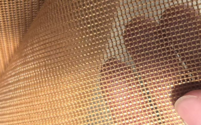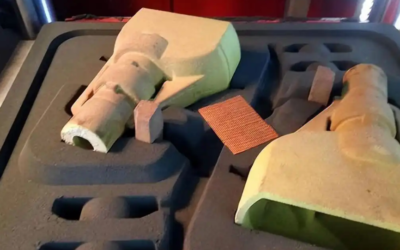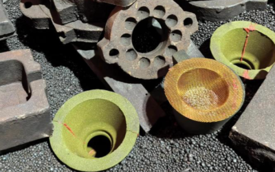
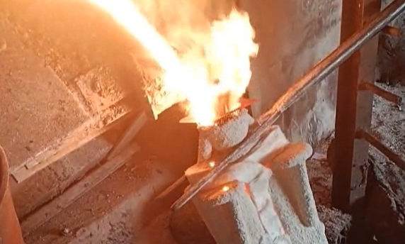
A wrong filter dimension means scrapped castings, a stalled pour, and a production manager asking why the gating system failed. If you have ever ordered a fiberglass mesh filter that arrived a few millimeters off from your sprue cup or riser design, you already know standard sizing charts fall short.
That is where custom dimensions come in. Getting the fit right means translating length, width, thickness, and mesh opening size directly to your specific casting setup, which a generic filter mesh size chart cannot do. This guide walks through the practical process foundry engineers use to define, communicate, and verify custom filter specifications before placing an order, so your next shipment fits the mold the first time.
How to Determine If You Need a Custom Size Filter Mesh
Not every Gating System fits a standard filter mesh chart. Here is how to tell quickly.
Go custom when your gating geometry is irregular. A flat square piece will not cover trapezoidal, fan-shaped, semicircular, oval, ring, curved, or polygonal sprue cups and runners, because the effective filtration area will not align. If your gating includes steps, slopes, locating slots, ribs, or parallel runners, a flat stock filter has nowhere stable to sit. For filters placed at the cup bottom, the sprue-to-runner junction, or tight pockets near the cavity, choose round, square, trapezoidal, or cup-style filters made directly to your pouring cup ID (frequently 100, 110, 115, or 120 mm).

Standard sizes fall short in these scenarios:
|
Situation |
Why standard fails |
|---|---|
|
300×300 mm / 400×400 mm cast iron sheets |
Works for flat, square layouts, but fails on ring gates, split flows, and notched seats |
|
450/900 mm roll stock, field-cut |
Supplier cuttable range runs 20×20–900×1000 mm, but cutting mixed shapes by hand generates high scrap loss |
|
Mixed alloy mesh needs |
Cast iron uses 1.5×1.5 / 2.0×2.0 mm, while non-ferrous alloys need 1.0×1.0 / 1.5×1.5 mm. Combining irregular shapes with multiple opening sizes makes custom orders cheaper than manual shop cutting |
The Hidden Cost of Field-Cutting
|
Factor |
Field-cut standard sheet/roll |
Direct custom order |
|---|---|---|
|
Labor |
Measuring, marking, trimming, deburring, and inspection |
Direct placement with no prep work |
|
Material yield |
Good for plain rectangles; poor for circles, trapezoids, and mixed shapes |
Nesting-optimized with higher overall yield |
|
Contamination risk |
Metal shavings, dust, and handling debris near the mold cavity |
Factory-finished and clean; no secondary processing |
|
Sealing |
Undersized cuts leak metal; oversized pieces warp or seat unevenly |
Sized to match seat dimensions, clearances, and locating features |
|
Design margin |
Requires a filter block 20–30 mm larger than the runner cross-section |
Margins, tabs, notches, and chamfers are built into the production drawing |
Use this to compare total cost:
-
Field-cut total = sheet price + cutting labor + inspection/cleaning + scrap loss + rework risk
-
Custom total = unit price + tooling/sample fee (if any) + freight
Run a pilot batch of 50–100 pieces. Track cutting hours, scrap weight, seat misalignment, and casting defects from inclusions. Switch to custom parts once shop labor and scrap scrap losses exceed the custom purchase price.
Scenarios Where Custom Is Almost Always the Right Call
Holding furnace / filter box filtration: Trough widths, support ledges, and refractory linings rarely fit standard square dimensions, and narrow seating faces allow metal bypass. Ceramic foam filters can be produced to custom lengths, widths, diameters, and thicknesses from 40×40 to 500×500 mm.
Launder filtration: Long, trapezoidal, or curved runners require filter dimensions matched to the actual flow cross-section, particularly during continuous or high-volume pours.
Pouring cup filtration: Round or tapered cups need disc, cup-style, or slotted filters. Flat squares shift and float at the base of the cup.
Multi-cavity / multi-branch gating: Total filtration area needs to measure 2–3 times the combined runner cross-section, with roughly 1 mm of seat clearance. When a catalog size cannot cover area, seat depth, and perimeter sealing at the same time, cut the filter directly to the gating drawing.
Thin-wall aluminum alongside high-tonnage castings: Mesh openings run from 1.0×1.0 mm for fine inclusion control up to 2.0×2.0 mm for heavy flow, requiring custom dimensions, thickness, and weave patterns for specific alloys and pour speeds.
Measure the Gating System and Determine Filter Outer Dimensions (Fiberglass Mesh Filter Dimensions)

Numbers on a drawing mean nothing until you measure the real opening. Before you call a supplier, grab a caliper and check the mold directly.
Measure the Minimum Flow Cross-Section, Not the Upstream Runner
Place the filter where the metal flow path is narrowest. Record the dimensions for whichever runner shape you have:
-
Round: opening diameter (Dr)
-
Square: width (Wr) and height (Hr)
-
Rectangular: length (Lr) and width (Wr)
-
Irregular runners: calculate the cross-sectional area in CAD, then note minimum width, maximum length, and the full boundary outline
Field Measurement Steps
-
Clear burrs, residual sand, and coating buildup from the seat.
-
Measure two perpendicular dimensions with a vernier caliper across at least three positions.
-
Take the smallest valid reading as your design baseline instead of averaging the numbers.
-
For tapered or filleted gates, measure across the filter support plane rather than the inlet’s upper rim.
Why the Outer Dimension Must Exceed the Runner
Suppliers recommend sizing the filter 10–20 mm larger than the flow cross-section on each side. That extra border provides a solid edge for sealing, clamping, and locating. If the filter matches the runner opening exactly, loose fitting gaps, cutting variances, crumbling sand edges, and heat warping will open a bypass route. Molten metal follows the easiest path, flowing around the mesh boundary instead of through it and letting inclusions slip straight past the filter.
Conversion examples:
– Round runner Dr = 60 mm → outer diameter around 70–80 mm (verify that the flange seats completely if you use a cup-style filter)
– Rectangular runner 80×50 mm → filter plane starting near 100×70 mm, prioritizing continuous support around the perimeter over expanding every side evenly when space in the cup is tight
Check Filtration Area, Not Just the Runner Projection
Aim for an effective filter area 2–4 times the raw runner cross-section. This offset compensates for typical mesh porosity of 50–60% and filtration efficiency between 60–80%. If you size the filter to match only the runner’s footprint, the pour will choke or pass through under-filtered.
|
Outline |
Dimensions the supplier needs |
|---|---|
|
Round |
Outer diameter, effective filter diameter, thickness, chamfer/fillet radius, locating notch or hole |
|
Square |
Outer edge, effective edge, thickness, corner radius, orientation mark |
|
Rectangular |
Outer length/width, effective length/width, thickness, fillet radius, clearance, datum corner |
|
Trapezoidal |
Top/bottom base, leg length or angle, height, thickness, radius, up/down marking |
|
Cup-style |
Flange OD, ID, cup depth, bottom filter diameter, wall thickness, flange thickness, taper, connection bore |
Standard mesh openings run 0.8, 1.0, 1.2, 1.5, 2.0, and 2.5 mm. Cut-piece stock spans 20×20 mm to 900×1000 mm, with 100×100, 150×150, and 200×200 mm being common fixed sizes.
Determining Filter Mesh Opening Size
Mesh count alone will not tell you what passes through a filter. Two filters labeled “30 mesh” can let different particle sizes through depending on wire diameter. For that reason, the mesh opening size in millimeters tells you far more than the nominal mesh count printed on a spec sheet.
Opening Size by Alloy Type
Different alloys carry distinct flow characteristics and inclusion loads. Match the opening size directly to the metal you are pouring.
|
Alloy |
Fine Filtration |
General Filtration |
Selection Logic |
|---|---|---|---|
|
Aluminum alloys |
0.8×0.8–1.2×1.2 mm |
1.5×1.5–2.5×2.5 mm |
Aerospace, thin-wall, die-cast, and high-purity parts favor 0.8–1.2 mm; standard gravity casting or high-flow setups use 1.5–2.5 mm |
|
Cast iron |
Not standard below 1.5 mm |
1.5×1.5–2.5×2.5 mm |
High temperatures and heavier inclusion loads push toward 1.5–2.0 mm; large castings or dirty iron use 2.5 mm |
|
Steel alloys |
Not standard below 1.5 mm |
1.5×1.5–2.5×2.5 mm |
High thermal and impact loads call for high-silica or ceramic media; general steel starts at 1.5–2.0 mm, larger pours use 2.5 mm |
|
Copper alloys |
Starts around 1.2–1.5 mm |
1.5×1.5–2.5×2.5 mm |
Small precision copper parts can test 1.5 mm; general copper castings run 2.0–2.5 mm to balance dross removal and throughput |
Selection order to follow:
1. Base the opening size on your target defects first. Fine inclusions, oxide films, and small dross particles require 0.8–1.2 mm.
2. Check that against flow rate and pouring cross-section. High flow, low metal head, or clogging risks require moving up to 1.5–2.5 mm.
3. Compare adjacent grades in initial trials, testing aluminum at 1.0 mm against 1.5 mm, or cast iron at 1.5 mm against 2.0 mm.
4. Specify the filter material, filtration area, thickness, operating temperature, and target alloy together. Fiberglass mesh built for aluminum cannot withstand the temperatures required for iron or steel.
Why “Opening Size” Beats “Mesh Count” on a Purchase Order
Mesh count indicates openings per linear inch, but leaves the open dimension variable. When the wire diameter changes, the clear hole changes with it, even at the identical mesh count.
Write purchase orders with explicit dimensions: square opening 1.00×1.00 mm, tolerance ±0.10 mm, wire diameter approx. X mm, open area ≥ X%.
The conversion works out as follows:
-
Mesh = 25.4 / (w + d)
-
w = 25.4 / Mesh − d
-
Open area A = (w / (w + d))² × 100%
Here, w represents opening size in mm and d represents wire diameter in mm. Thicker wire shrinks the opening, reduces total open area, and increases pressure drop, though it gives the mesh better mechanical strength and erosion resistance.
Example: A 30-mesh fabric woven with 0.30 mm wire leaves a clear opening of 25.4/30 − 0.30 = 0.547 mm. Spec sheets frequently list 0.85 mm instead, confusing center-to-center pitch spacing with the net opening.
Custom Range: 0.8–3.0 mm and Beyond
Standard grades include 0.8, 1.0, 1.2, 1.5, 2.0, 2.5, and 3.0 mm.
0.8–1.2 mm: Fine filtration for high-purity aluminum and thin-wall precision castings. These sizes carry higher flow resistance and clog more quickly.
1.5–2.5 mm: General-purpose range covering most aluminum, cast iron, steel, and copper work.
2.5–3.0 mm: High-flow pours catching coarse particles, with lower capture rates for fine inclusions.
Below 0.8 mm: Switch to ceramic foam filters, sintered metal elements, or multi-stage filtration. Woven wire mesh does not hold reliable tolerances down at this size.
Above 3.0 mm: Use coarse ceramic foam, heat-resistant metal grids, perforated plates, or a pre-settling chamber. To catch fine inclusions at this volume, back up that coarse stage with a 1.0–1.5 mm fine filter.
Outside the 0.8–3.0 mm window, write acceptance criteria around actual opening dimensions, filtration area, pressure drop, temperature rating, and target particle size rather than mesh count.

Match Thickness and Material Grade (Material Grade & High Temperature Filter Material)
Pick the wrong grade and the filter softens mid-pour. That failure costs more than a scrapped casting—it burns trust with your production manager.
Match Material Grade To Pour Temperature
|
Metal |
Grade Code |
Filter Material |
Typical Temp |
Selection Rule |
|---|---|---|---|---|
|
Aluminum |
FM-07-AL |
Alumina ceramic foam, high-silica/high-temp fiberglass |
680–780°C |
Rated temp ≥50°C above peak pour temp |
|
Cast Iron |
FM-07-FE |
SiC, sintered alumina, high-silica |
1300–1450°C |
Check thermal shock and iron erosion resistance |
|
Steel/Alloy Steel |
FM-07-ST |
Zirconia, alumina, SiC |
1500–1700°C |
Carbon/low-alloy steel needs ≥50°C margin; stainless needs more |
|
Copper/Brass/Bronze |
FM-07-CU |
Alumina, mullite, SiC, high-silica |
1000–1200°C |
Check wetting, erosion, softening point |
Standard fiberglass softens around 850°C, which rules it out for long-duration or high-impact pours above 800°C. Keep it strictly for lower-temperature aluminum runs.
Thickness By Metal Class
|
Metal |
Recommended Thickness |
Why |
|---|---|---|
|
Aluminum alloys |
0.35–0.55 mm |
Lower temp, lower density, less impact load |
|
Cast iron / steel |
0.65–0.85 mm |
Higher heat and mechanical erosion demand more body |
|
Copper alloys |
0.55–0.75 mm |
Falls between aluminum and iron; go thicker under high flow or static pressure |
Thickness and temperature move together. As pour temperatures push toward the filter’s rated ceiling, softening and chemical wear speed up. Add thickness or upgrade the material grade instead of just expanding the filtration area. Steel poured near 1600–1700°C requires zirconia or high-purity SiC; extra thickness will not save an under-graded filter under that kind of heat.
Datasheet Checklist Before You Order
-
Confirm the material spec explicitly names Al₂O₃, SiC, ZrO₂, mullite, or high-silica fiberglass. A generic label like “high-temp fiber” guarantees nothing.
-
Distinguish the continuous working temperature from the peak temperature or melting point.
-
Keep a 50°C safety margin between your peak pour temperature and the filter’s rated continuous temperature.
-
Request chemical composition, bulk density, porosity, compressive strength, thermal shock data, and batch inspection reports.
-
Verify that quoted thickness means net finished thickness, without coatings or backing layers included.
-
Ask for wetting and erosion test data at your actual pour temperature rather than a generic rating.
Determine Cutting Format and Roll Specifications (Custom Cut Filter Cloth & Roll Specifications)

Four format choices drive your total cost before a single filter reaches the pour line.
Pre-cut single pieces span 20×20 mm to 900×1000 mm in rectangular or round shapes. They arrive ready to install without shop-floor cutting or scrap, though each size adds tooling costs and another SKU to inventory. Full sheets cut to equipment footprints fit large, stable filter frames with few seams, but they are bulky to ship. Roll stock and cup-style preforms (100/110/115/120 mm OD) round out the options for continuous lines and sprue-cup assemblies.
Roll Width and Length Selection
Standard roll widths are 450 mm and 900 mm, and suppliers can slit custom widths down to 50 mm. If your target width is close to 450 mm, order 450 mm rolls. If you need wide coverage or cross-cutting flexibility, buy 900 mm master rolls and slit them as needed. Leave a 5–15 mm trim allowance instead of matching the width down to the millimeter, which leaves room for edge fraying and fixture alignment.
Standard lengths include 100 m rolls for pilot runs and multi-SKU shops, 150 m for steady mid-volume production, and 200 m rolls to reduce changeovers on continuous lines. Cloth thickness runs 0.35–0.60 mm, with weights between 150 and 350 g/m².
Calculate required roll length as (piece length × pieces per roll) ÷ yield rate, estimating yield at 90–95% until trial cuts give you verified scrap rates.
Pick Rolls vs. Pre-Cut
Choose rolls if you run only a few specs, handle high monthly volumes, and have cutting equipment on the floor. Choose pre-cut pieces if you manage shifting order sizes, wide part variations, or have no dedicated cutting line. Most foundries run a hybrid approach, using 900 mm rolls for high-volume standard parts and pre-cut or cup-form pieces for low-frequency castings.
Fill Out a Complete Foundry Filter Specifications Request
One missing dimension on a request form can send an entire sample batch back to tooling. Foundries that ask for a generic “300×300 filter” usually re-order twice. Supplying a complete specifications request eliminates guesswork before quoting starts.
Account and Order Basics
Open the form with the customer name, plant or project name, contact person, email, phone number, and supplier name (FoundryMax, for example). Add the request date, drawing number and revision, expected mass-production date, sample quantity, first PO volume, and projected monthly or annual usage. Finish this section with target unit price, lead time, trade terms, destination port, and packaging method (bulk, carton, pallet, vacuum bag, or moisture-proof wrap), along with pieces per box and label details.
Process Data
List the alloy grade, pour temperatures (normal, minimum, and maximum in °C), piece weight, total metal flow, pour time, and pour method: gravity, low-pressure, high-pressure, tilt, or continuous. Name the filtration position, whether that is the sprue, runner, ingate, ladle, launder, holding furnace outlet, or tundish.
Use supplier baselines as your starting point. FoundryMax lists maximum operating temperatures near 1250°C for alumina (aluminum), 1560°C for SiC, and 1760°C for zirconia, with ceramic foam specified between 10 and 60 PPI. Fiberglass mesh openings run 1.5×1.5, 2.0×2.0, and 2.5×2.5 mm, with 300×300 and 400×400 mm standard sheet sizes.
Dimensional Specs — Separate Product Size From Seat Size
This step causes the most production delays. Record the installation location, seat or trough length, width, depth, and whether the seat includes steps, fillets, locating pins, or clamping structures. Next, give the finished shape (square, rectangular, round, ring, or custom), outer dimensions, effective filtration area, border width, and notch or chamfer size. Note the clearance, compression allowance, and sealing method between filter and runner, along with unit weight and maximum allowable weight.
A 300×300 mm filter differs from a 300×300 mm seat cavity. State both measurements explicitly, or the part will not drop into place.
Material and Tolerance Block
Specify the filter type (fiberglass mesh, Honeycomb ceramic, SiC foam, zirconia foam, or Alumina foam), material grade and chemistry, mesh opening in mm×mm (or PPI for foam), thickness with tolerances, porosity, flow rate, filtration precision, thermal shock resistance, continuous service life, and compressive or tensile strength. State any requirements for asbestos-free, low-volatile, low-shedding, or food- and automotive-grade materials, plus color, surface treatment, or pre-coating needs.
Use these as reference points:
|
Alloy |
Common Opening |
Note |
|---|---|---|
|
Aluminum |
1.0×1.0 (fine) / 1.5×1.5 (general) / 2.0×2.0 mm (high flow) |
Room-temp warp/weft tensile strength can be specified above 600 N/5cm |
|
Gray iron |
1.5 mm ≤100 kg / 2.0 mm ≥100 kg |
— |
|
Ductile iron |
2.0 mm ≤100 kg / 2.5 mm ≥100 kg |
— |
Define your tolerances clearly: order quantity plus spare ratio, length/width/diameter/thickness tolerance (±0.5 mm or supplier standard), mesh opening limits, and visual defect allowances covering cracks, chipped corners, delamination, blocked holes, burrs, and warping. List inspection ratios for visual, dimensional, and functional checks, batch traceability criteria (production date, furnace lot, raw material lot), required documentation (dimensional report, material test report, COA, third-party report), and procedures for non-conformance, including replacement, rework, returns, and claim windows.
CAD or Photos — Don’t Skip This
Drawings should show the datum face, installation direction, flow arrows, critical dimensions, tolerances, fillets, steps, and locating features. Provide both PDF and DWG or DXF files, and state on the drawing which revision is final.
If you lack CAD files, submit marked photos with scale instead. Photograph the front, back, side, installation groove, and any damaged areas with a steel ruler or caliper placed beside the part. Mark the A, B, and C dimensions, metal flow direction, filtration face, and the boundary between the effective filtering area and the solid border.
Five Communication Mistakes That Trigger Re-Tooling
Giving only “300×300 mm” — The supplier builds to outer dimensions when your seat cavity measured 300×300 mm, leaving you with a filter that cannot seat.
Writing only “2 mm mesh” — Without clarifying clear opening, PPI, or wire diameter, the supplier might deliver a 2×2 mm woven mesh, 20–30 PPI foam, or a 2 mm-thick sheet.
No flow arrow — The shop installs the filter backward, triggering edge leakage or premature clogging.
Unscaled photos — Toolmakers misread fillets, steps, or notches, forcing a complete mold redesign on the first run.
Omitting thickness — The supplier mistakes a 1.5 mm sheet thickness for a 1.5 mm opening size. In foundry filtration, thickness and aperture size are independent values.
What To Attach When You Send the RFQ
Bundle everything in one submission:
-
Alloy grade, pour temperature range, casting piece weight, and filtration position
-
CAD drawing or marked reference photos
-
Target dimensions, thickness, mesh or PPI rating, and material grade
-
Sample quantities: request 10–20 pieces per spec minimum to cover first-article inspection, in-process trials, and destructive tests
-
Sample labeling requirements: spec number, lot, production date, material type, and flow orientation
-
A sample acceptance criteria sheet covering dimensions, thickness, aperture size, weight, visual quality, thermal shock resistance, and pour performance
-
A requirement for supplier documentation: dimensional inspection sheet, material composition report, COA, and batch photos
-
A written sign-off confirming that raw materials, molds, apertures, and manufacturing methods remain frozen after first-article approval unless authorized in writing
-
A requirement for 2D sign-off drawings and pre-production sample photos before sample tooling begins
-
Agreed response times: formal quote within 2 business days, drawing sign-off within 1 day, and sample delivery in 7–14 days, all confirmed in writing
FoundryMax accepts custom orders sized directly to launder or tundish dimensions and recommends matching opening size to inclusion type and size. Its product sheets list material composition, temperature limits, and porosity or mesh data, providing the exact values needed for the material grade, maximum operating temperature, structure, and opening size fields on your form.
Pre-production Verification
A rejected first article derails the entire production schedule, far beyond the cost of a missed dimension. Before shipping custom fiberglass mesh filters in volume, lock the paperwork and the physical part together.
Freeze the documentation first. Confirm that the PO, mold drawings, datasheet, and inspection specs all carry matching revision numbers. Tag every dimension, mesh opening, and drawing note with a bubble number to build a complete characteristics list.
Measure, don’t eyeball. Use calibrated calipers, micrometers, or a projector/CMM to check outer length, width, border width, bend height, and locating holes against mold drawings. For mesh opening size, measure pitch and aperture across the center, all four corners, and the edges rather than checking a single spot. Record wire diameter and thickness at multiple positions so burrs or solder joints do not skew the readings. Trace the material grade and heat or lot number back to the certificate; missing paperwork here is a leading cause of FAI rejections.
Run temperature-cycle testing on sampled first articles. Record initial weight, thickness, and flatness, run the parts through room temp → working temp → peak temp, then re-check for mesh opening shifts, warping, cracking, and oxidation weight gain.
Log every result as “spec—measured value—tolerance—verdict.” Any deviation halts mass production until you resolve it.
Conclusion
Sizing fiberglass mesh filters comes down to straightforward engineering. You need accurate gating system measurements, the right mesh opening for your alloy and pour rate, and a thickness or density grade that holds up to molten metal flow. Miss any of those, and you risk bent sprues, metal bypass, or filters that collapse mid-pour.
Beyond cutting down on scrap, proper sizing creates a repeatable system. Once you document your metal casting filter specifications on a clear request form, reorders move faster and supplier conversations stay productive. You eliminate the guesswork and stop settling for custom-cut filter cloth that only almost fits.
Pull your gating prints, measure your pour cup and runner dimensions, and send a complete spec sheet to your supplier instead of a verbal request. That five-minute step saves a shift-long headache later. Foundries that provide exact specifications get reliable filters and fewer surprises on the shop floor.