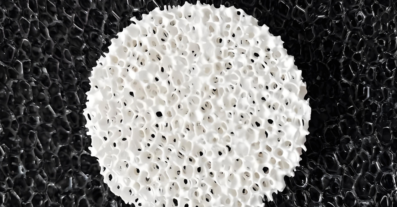
Every foundry engineer knows the frustration of looking at two refractory materials with nearly identical chemistry, only to find that one insulates twice as well as the other. That performance gap rarely comes down to the base ceramic. It comes down to trapped air: trillions of microscopic pockets inside a solid matrix that stop more heat than most procurement spreadsheets account for.
Understanding the physics behind porous thermal insulation matters on the plant floor. Knowing how pore structure disrupts phonon transport, and how cell geometry and connectivity shift performance under real furnace conditions, helps you defend material choices with data instead of guesswork. Below, we walk through the mechanics of heat transfer in ceramics, examine why lab data often diverges from field results, and turn that science into a procurement checklist that protects your furnace lining, energy budget, and production schedule.
The Science Behind Low Thermal Conductivity in Porous Ceramics
Numbers tell this story better than theory ever could. Push porosity in a cordierite ceramic from 87% to 90%, and thermal conductivity drops from about 0.12 to 0.06 W·m⁻¹·K⁻¹. That is a 50% reduction from a 3-point shift. Porous alumina/zirconia samples at 69% porosity run between 0.23 and 0.28 W·m⁻¹·K⁻¹. Pores break up a continuous solid into a winding, interrupted path for heat. Every time heat crosses a solid-gas boundary, thermal resistance stacks up.

Why Pore Size Isn’t the Whole Story
At equal pore volume fraction, smaller pores usually win by creating more interfaces, thinner solid bridges, and more tortuous paths. But that rule bends at high porosity. Larger pores help once total porosity climbs because they shrink the connected solid cross-section further. A 40 μm pore-former in alumina produces 69.5% porosity and 0.23 W·m⁻¹·K⁻¹ conductivity. Under different conditions, smaller pore-formers pushed conductivity up to 0.483 W·m⁻¹·K⁻¹. Pore structure conductivity is never a single-variable equation.
Pore geometry and orientation matter just as much as size:
– Closed, uniformly distributed pores outperform open, connected networks for insulation
– Connected pores cut solid thermal bridges but risk gas convection channels
– Flattened pores with the short axis perpendicular to heat flow lower conductivity further at identical porosity and pore size distribution
The Air-Trapped-Pores Insulation Math
Dense ceramic matrices conduct at 10–100 W·m⁻¹·K⁻¹. Air sealed inside closed pores conducts at 0.024–0.026 W·m⁻¹·K⁻¹; argon drops to 0.018. That is a 400x to 4,000x gap. One modeled system paired 0.395 W·m⁻¹·K⁻¹ solid conductivity with 0.0262 W·m⁻¹·K⁻¹ pore air, landing at 0.0569 W·m⁻¹·K⁻¹ overall. In that simulation, conductivity scaled almost linearly with porosity.
Closed pores beat open ones for convection control. Small, sealed cavities trap gas molecules before they organize into circulating flow. Wall friction and limited cavity volume shut down natural convection, leaving only conduction through molecular collisions. Closed-pore alumina sits at 0.20–0.50 W·m⁻¹·K⁻¹; closed-pore silicon carbide runs 0.40–0.69 W·m⁻¹·K⁻¹—both lower and more stable than open-cell equivalents.
Phonon Scattering: The Microstructure Layer
Crystalline ceramics move heat primarily through phonons, which are lattice vibrations. Grain boundaries reflect, refract, and scatter phonons inelastically, shortening their mean free path. In polycrystalline ceramics, calculated phonon mean free paths often fall below grain size, proving that grain boundaries dominate scattering.
Pore walls, residual glass phases, dislocations, and point defects add more scattering sites on top of that. In Silicon carbide, rising porosity reliably lowers conductivity by shrinking the conductive cross-section and shortening the phonon mean free path at pore-grain interfaces. Temperature shifts the balance too. At low temperatures, grain or structural boundaries limit phonon travel. At high temperatures, phonon-phonon Umklapp scattering takes over as the main restriction, so grain boundaries, pores, and defects continue suppressing lattice heat transport across all temperatures.
Design Priorities That Fall Out of the Physics
-
Push total porosity up, but block through-connected large channels
-
Favor closed or controlled-connectivity fine pore structures
-
Maximize pore-grain boundary interface area and solid path tortuosity
-
Keep grain size near or below the phonon mean free path
-
Fill pores with air or low-conductivity inert gas
-
Design pore shape and orientation to minimize solid bridges along the heat flow direction
Temperature-Dependent Behavior: Why Room-Temperature Data Misleads Foundry Decisions
Radiation ignores your datasheet. As operating temperatures climb, it scrambles the thermal conductivity rankings you measured at room temperature. Radiative equivalent conductivity scales with the cube of absolute temperature (λ_rad ∝ T³), so while the effect stays small at ambient levels, it surges under furnace heat.
Three thresholds matter for foundry applications:
Above 500–700°C: radiation begins to register in low-density materials. One fiber-insulation study showed radiation had minor influence below 773 K (~500°C).
Above 800°C: pore gas conduction no longer accounts for total heat flow. Radiative penetration, pore size, material translucency, and surface emissivity all start dictating measured conductivity. NASA refractory fiber data shows radiative heat transfer matches gas conduction around 1000 K (~727°C), backing this 800°C working limit.
Above 1000°C: radiation often becomes the primary heat transfer path. Materials picked for low conductivity at room temperature can flip rankings when exposed to molten metal contact, furnace linings, gating systems, or hot molds.
Near 1400°C, sintering, pore shrinkage, phase transformation, and dimensional contraction create a second issue. Fiber-based or porous ceramics that test well at room temperature lose their insulating advantage once structural densification takes over in service.
|
Material Class |
Room Temp |
800°C |
1000°C |
1400°C |
|---|---|---|---|---|
|
Foam refractory |
0.10–0.30 W·m⁻¹·K⁻¹ |
0.15–0.35 |
0.15–0.35 |
0.25–0.60 |
|
Fiber-based insulation |
0.03–0.10 |
0.08–0.20 |
0.10–0.20 |
0.30–0.50 |
|
Hollow particle coating |
0.08–0.25 |
0.15–0.30 |
0.20–0.40 |
0.35–0.70 |
One high-porosity rare-earth zirconate ceramic measured 0.0642 W·m⁻¹·K⁻¹ at room temperature, then rose to 0.1467 W·m⁻¹·K⁻¹ at 1200°C—a 129% jump. Room-temperature numbers cannot predict that trajectory.
Structure-Property Relationships: Pore Size, Distribution and Connectivity
Seventy nanometers is the threshold most spec sheets leave out, yet it matches the mean free path of air molecules at 20°C and 1 atm. Drop pore diameter below 70 nm, and gas transport shifts from normal diffusion to Knudsen diffusion, where molecules collide with pore walls far more often than with each other. Gas-phase heat transfer collapses. Push pore diameter above that line, and internal convection currents begin to form, giving back the thermal resistance you worked to engineer away.
This explains why polyimide aerogel films reach 0.019 W·m⁻¹·K⁻¹—near the theoretical floor—while maintaining 89.6 MPa tensile strength. Fine, evenly distributed pores stretch the conduction path through the solid skeleton without sacrificing mechanical integrity. That combination is rare, but it sets the performance benchmark for foundry-grade insulation.
The Connectivity Trade-Off You Can’t Engineer Around
Pore connectivity dictates whether porosity helps or hurts:
Higher porosity → fewer solid thermal bridges, higher tortuosity, and lower conductivity
Higher connectivity or larger pore size → gas convection rises, tortuosity drops, and conductivity climbs back up
Oversized pores or pore-neck defects → load-bearing cross sections thin, reducing compressive and flexural strength
Strongly connected pore networks raise overall thermal conductivity even when total porosity stays constant. To keep conductivity low while protecting mechanical strength, use a dual-scale structure of mostly fine, closed pores combined with a controlled share of larger, isolated voids. Orienting flattened or elongated pores with their short axis perpendicular to heat flow lengthens the thermal bridge path further.
Closed Pores: The Quiet Engineering Advantage
Closed-cell structures do more than block convection. They cut off moisture absorption, liquid penetration, and capillary transport. Open-pore materials, by contrast, take up gas in direct proportion to how connected their pores are. In a furnace environment where humidity and metal splash are constant hazards, that barrier protects long-term insulation life. Radial measurements on closed-pore fiber and nanofiber foams at about 8% relative humidity show values of 22–27 mW·m⁻¹·K⁻¹.
Pushing closed-pore volume too high brings its own failure modes. Sintering bonds weaken, crack resistance drops, and trapped gas creates reliability risks during thermal cycling. The target is balancing closed-pore fraction, wall thickness, and skeletal strength rather than chasing total closure for its own sake.
Fiber Networks: Lightweight Insulation Through Geometry, Not Just Porosity
Fiber refractories reach low conductivity through contact geometry rather than pore volume alone. They divide heat flow across thousands of winding paths formed at fiber-to-fiber contact points. Each contact adds interfacial thermal resistance, while each gap between fibers shrinks the continuous solid cross section. This delivers low conductivity at low density, provided the network geometry is sound.
What a well-designed fiber network needs:
– High aspect-ratio fibers
– Even fiber distribution with minimal clumping
– Enough node connections for structural integrity, without forming continuous solid thermal bridges
– Controlled, consistent pore size between fibers
Alumina-silica fiber refractories typically run 40–70 vol% open porosity, with an apparent density of 0.3–1.2 g/cm³ and thermal conductivity of 0.2–0.8 W·m⁻¹·K⁻¹ at 1,000°C.
Where this shows up on the foundry floor: – Riser sleeves and insulating covers for steel, iron, and high-temperature alloy castings – Localized hot-spot insulation in sand or shell molds, reducing shrinkage porosity risk – Backing layers or local thermal barriers in investment casting shells – Lightweight refractory lining around molten metal transfer systems, gating, and crucible exteriors
Open fiber networks should never sit in direct contact with molten metal. Liquid infiltration, moisture pickup, and thermal shock degrade open fibers quickly. Use low-permeability closed-pore composites or dense refractory layers at the hot face, and place open fiber insulation on the outer thermal envelope where its tortuosity delivers the greatest benefit.
Porosity vs Mechanical Strength: The Foundry Engineer’s Trade-off Decision
Nobody gets a free lunch with porosity. Thermal conductivity drops almost linearly as pore volume rises, but mechanical strength drops off an exponential cliff. That mismatch in curves is where procurement decisions go wrong.
Which Model Actually Predicts Your Material’s Behavior
Two models cover most refractory cases, and picking the wrong one skews your conductivity predictions:
-
Maxwell-Eucken fits closed, spherical, isolated pores dispersed in a continuous solid matrix.
-
Landauer fits open pore networks. It tracks Maxwell-Eucken closely below 15% porosity, then predicts behavior better between 15% and 65%.
Past 65% porosity, the solid phase must stay continuous or the structure loses baseline mechanical strength. Treat that 65% mark as a warning threshold where insulation gains start trading hard against structural stability. Below it, calibrate either model against measured bulk density, open porosity, and solid-phase conductivity before trusting the output.
Hard Numbers on the Strength Side
Foam glass tests show this asymmetry clearly: conductivity falls almost linearly with porosity, while compressive and flexural strength collapse exponentially, bottoming out near 4 MPa at the lowest tested point. Compare that to dense corundum refractories holding 3% open porosity with 110 MPa cold crushing strength. Published ladle refractory patents report 2.5-4% porosity paired with 450-600 kgf/cm² compressive strength (about 44-59 MPa). Steel fiber-reinforced castables used in casting applications reach at least 80 MPa cold crushing strength and survive 30+ cycles of 1,100°C water-quench thermal shock testing.
Matching Porosity to Lining Zone, Not the Whole Furnace
|
Zone |
Failure Mode |
Material Choice |
|---|---|---|
|
Furnace bottom/wall insulation |
Heat loss, thermal shock |
Mid-high porosity lightweight brick/castable, layered behind a wear face |
|
Tap hole, door, melt impact zones |
Erosion, mechanical impact |
Low open-porosity, high-alumina or corundum castable, CCS ≥80 MPa |
|
Ladle slag line |
CaO-SiO₂-FeO slag attack |
≥75% Al₂O₃ corundum-mullite, HMOR >8 MPa at 1400°C |
|
Ladle permanent layer |
Long-term load bearing |
Mid-strength castable, higher porosity than working layer |
|
Tundish permanent layer |
Dimensional stability at temperature |
Dense/mid-porosity castable, 80-100 mm typical |
|
Tundish working layer |
Erosion, spalling per heat |
Fast-install sacrificial layer, low porosity defects, 1520-1580°C service |
|
Submerged nozzle, air-permeable brick |
Clogging, flow control |
Controlled local porosity only; main body stays high-strength |
Where Thin Solid Bridges Fail First
As porosity climbs and pore walls thin out, load paths shift from a continuous skeleton to a handful of narrow necks. Stress concentrates at those points, triggering brittle fracture, edge chipping, through-cracks, and post-installation crushing well before average compressive strength numbers indicate trouble. This risk sharpens past 65% porosity. At that stage, verify that the solid phase still forms a connected network instead of relying on the average strength specification.
Self-flow tundish castables reduce this risk by limiting gas pockets, local hot spots, and localized erosion sites. Uneven coverage or trapped air during installation creates weak zones that erode quickly under metal impingement.
Installation controls that protect thin-wall porous materials:
– Limit wedging force and point loads during bricklaying.
– Support lightweight porous brick across the full face, and avoid striking thin ribs directly.
– Inspect for edge chipping, through-cracks, and pore interconnection after lifting or cutting.
– Place dense protective layers or precast blocks at impact zones instead of exposing thin-wall insulation directly.
Layer materials by function instead of attempting to optimize a single material for the entire furnace. High-porosity material belongs in the backing insulation. Low-porosity, high-strength material belongs at the metal contact, impact zones, slag line, and wear faces.
Foundry Application Scenarios: Where Porous Ceramics Deliver Maximum Value
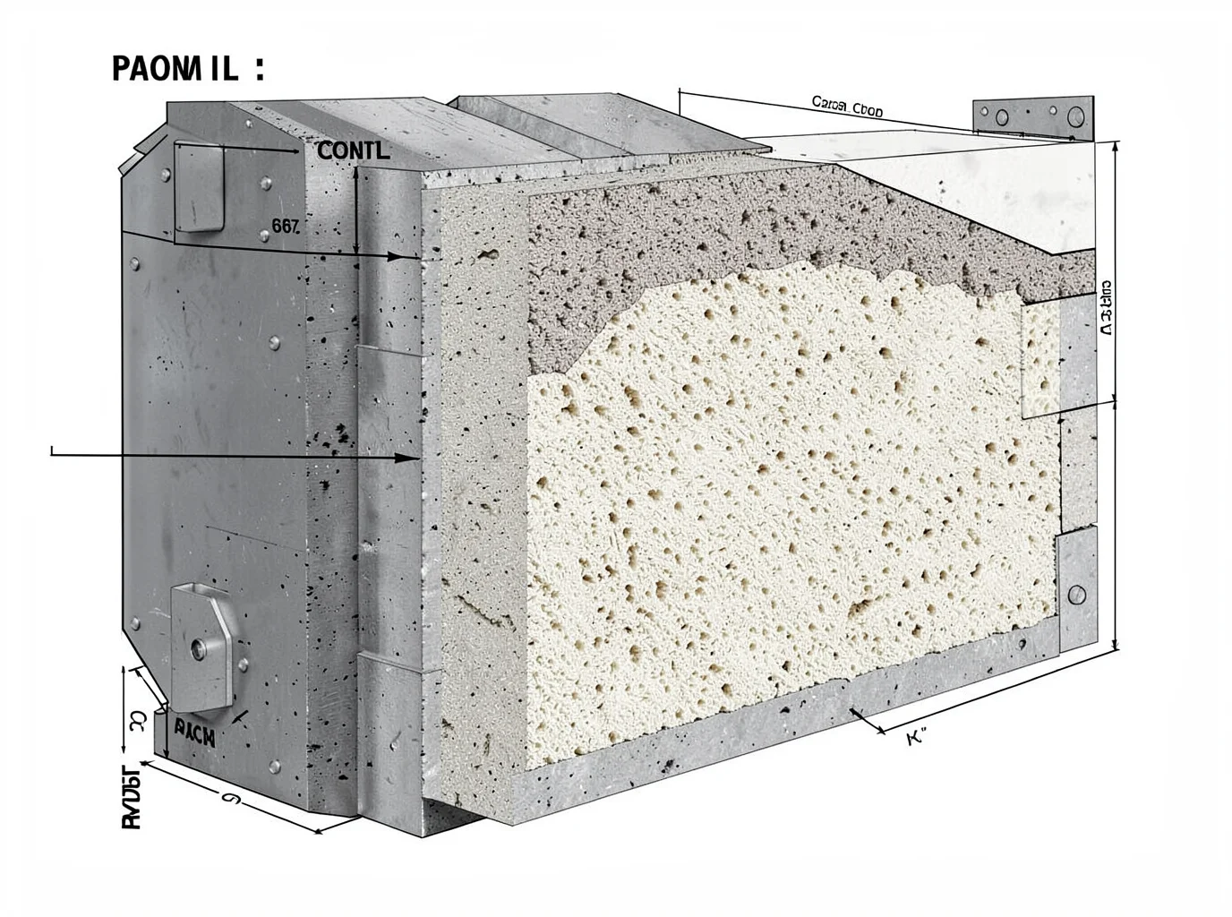
A furnace lining is a stack of zones, each carrying distinct thermal, mechanical, and chemical demands. Matching porosity grade to zone function keeps the furnace running and avoids unscheduled downtime.
Backing Insulation (Cold Face)
This layer never touches molten metal. It exists to cut shell temperature and heat loss, so corrosion resistance is not a concern. Closed-cell or high-porosity silica-based and glass-ceramic foams work best here:
-
85–92 vol% porosity
-
0.08–0.15 W·m⁻¹·K⁻¹
-
50–100 mm thickness
-
Working range: 200–400°C
Closed-pore structures also lower permeability and cut the risk of gas channeling through this cooler zone.
Hot Face Support Layer
Here, mechanical demands limit how porous the refractory can be. Alumina-silica, zirconia, or porous SiC composites balance refractoriness, thermal shock resistance, and erosion resistance against molten metal exposure:
-
60–75 vol% porosity
-
0.3–0.5 W·m⁻¹·K⁻¹
-
0.8–1.2 g/cm³ density
-
50–100 mm thickness, rated for 1500–1700°C
Don’t chase maximum porosity at the hot face. While higher porosity drops thermal conductivity, it also reduces compressive strength and resistance to metal penetration. In the melt-impingement zone, use a denser surface layer and back it with porous ceramic.
Insulating Brick, Burner Block, Lid, and Thermal Shields
Insulating brick on walls, floors, and thermal bridges: 0.1–2 W·m⁻¹·K⁻¹ depending on grade. At ~70% porosity, heat transfer drops 95% compared to dense ceramic. Pay close attention to joints, anchors, and compression allowances, which turn into thermal bridges if overlooked.
Burner block: porous alumina, mullite, or SiC, built “insulating outside, erosion-resistant inside.” Pores cushion thermal expansion, and tested samples survive 100+ heat/cool cycles without cracking, though service life varies with pore size, support strength, and flame velocity.
Furnace lid: lightweight porous ceramic panels paired with fiber modules lower lifting loads and heat loss. Secure them with a rigid anchoring frame to prevent sagging and opening joint gaps.
Thermal shields (doors, peepholes, tap holes, induction coil gaps): closed-pore SiC runs 0.40–0.69 W·m⁻¹·K⁻¹, while closed-pore microsphere material runs 0.10–0.15 W·m⁻¹·K⁻¹. Above 1000°C, add surface reflective layers or choose finer pores, because single-layer high-porosity material loses insulating value fast past that threshold.
Mold and Core Insulation: A Different Set of Rules
Casting molds and cores prioritize dimensional accuracy over thermal insulation. High-performance ceramic cores demand low thermal expansion, minimal gas release, and phase stabilization after 1200–1250°C heat treatment, keeping porosity below 10% with particle sizes around 50–450 µm.
Porous ceramics belong in core backing, local hot-spot control, thin-wall mold insulation, and controlled-permeability zones rather than on the forming face itself. High open porosity on a molding surface absorbs binder and metal, increases surface roughness, and lowers flexural strength. The standard approach pairs a dense working face with a porous backing layer. The dense layer preserves dimensions and surface finish, while the porous backing reduces heat flow and thermal stress.
Match porosity grade to function:
|
Need |
Porous Ceramic Choice |
|---|---|
|
High dimensional precision |
Low-expansion silica, zircon, alumina-mullite |
|
Fast cooling/demolding |
Moderate porosity to avoid overinsulating and dragging out solidification |
|
Gas venting |
Connected pores + dense metal-contact face/filter layer to block melt penetration |
|
Repeated cycling |
Closed or fine-pore structure for durability |
Material Selection Checklist: A Practical Framework for Foundry Procurement
A spec sheet full of impressive numbers means nothing if nobody checked how those numbers were generated. Before issuing a purchase order, run every supplier claim through this checklist.
Demand Full Test Context, Not Just the Number
Require the test method, specimen density, temperature, atmosphere, direction, and uncertainty on every datasheet. A thermal conductivity figure without an associated temperature point is practically useless. Benchmark quotes against known baselines: insulating fireclay brick runs as low as 0.16 W/m·K at 800°C, high-purity alumina sits near 5–6 W/m·K at 1000°C, and recrystallized SiC climbs to 40–50 W/m·K at 1000°C for rapid heat transfer. ASTM C201-24 standardizes comparative testing up to 28.8 W/m·K on a 25 mm specimen.
Set a Temperature Margin
Record normal, peak, and upset temperatures, along with cycle frequency and metal or slag contact duration. Add a 100–150°C safety margin above your measured peak temperature as an initial screening rule. A material’s temperature rating does not guarantee compatibility with your alloy, flux, or wetting conditions, so check those factors on their own.
Normalize Before You Rank Suppliers
Compare apparent and bulk density on the same basis. Require conductivity and strength data at matching points across 200, 400, 600, 800, and 1000°C. Keep air, inert, reducing, and vacuum atmosphere data separate, because oxidation-sensitive SiC and carbon results do not transfer across different atmospheres. Ask for data from at least three specimens, including the mean, minimum, and standard deviation. Send retained samples to an ISO/IEC 17025 lab when qualification stakes are high.
Check Porosity Against Penetration Risk
High porosity improves insulation, but it raises the risk of metal and slag penetration. Low porosity gives better corrosion resistance at the expense of heat retention. Pull water absorption, open porosity, and permeability as separate values instead of accepting a single blended number.
Match Zone to Material
-
Hot-face/impact zones: Dense, low-porosity refractory or SiC-based material. FoundryMax’s SiC ceramic foam filter rates to 1500°C for gray iron, ductile iron, aluminum, and copper. Use this rating strictly as a filtration benchmark rather than a lining qualification.
-
Transition layer: Medium-density alumina or fireclay to smooth out thermal gradients.
-
Back-up insulation: Porous ceramic or fiber-based material. Adding fiber cuts conductivity by 20–60% compared to dense refractory, but it requires erosion protection.
Incoming-lot chemistry matters just as much. FoundryMax kaolin benchmarks at SiO₂ 46–48%, Al₂O₃ 37–40%, Fe₂O₃ ≤0.40%, D50 4–8 µm, and LOI 13–15%. Use these parameters for lot control, and continue running mechanical and physical tests on finished products.
Conclusion
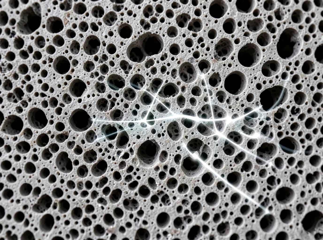
Low thermal conductivity in porous ceramics comes down to physics you can engineer. Trapped air pockets disrupt phonon pathways, pore architecture dictates whether heat sneaks through or scatters into dead ends, and that performance shifts once your furnace hits operating temperature. A room-temperature spec sheet from your supplier tells only half the story.
Every lining decision is a trade-off between insulation and mechanical durability, and getting that balance wrong shows up later as blown energy budgets or premature refractory failure. Engineers who understand pore structure, connectivity, and thermal resistance at a microstructural level make better procurement calls.
Before your next material spec review, pull the checklist from this guide and run your current supplier’s data through it. If the numbers don’t hold up at actual operating temperatures, you have your answer.
If you need a second opinion on your refractory selection, FoundryMax’s technical team reviews specs daily. Reach out before you sign the next purchase order.