Choosing the wrong filter doesn’t just reduce yield — it can wreck an entire pour. Yet across foundries worldwide, filter selection still gets treated as an afterthought. A box to check. Not a decision that shapes metal cleanliness, flow consistency, and scrap rates.
Here’s the reality: aluminum, iron, and steel each need a different filtration approach. Pouring temperature, inclusion chemistry, and flow dynamics vary too much between metals. No single filter material covers all three.
This guide breaks it down clearly:
-
Which filter types perform best for each metal
-
What the data shows about pore size and material selection
-
How to build a decision framework based on your process — not just your supplier’s catalog
What Are Casting Filters and Why Does Metal Type Change Everything
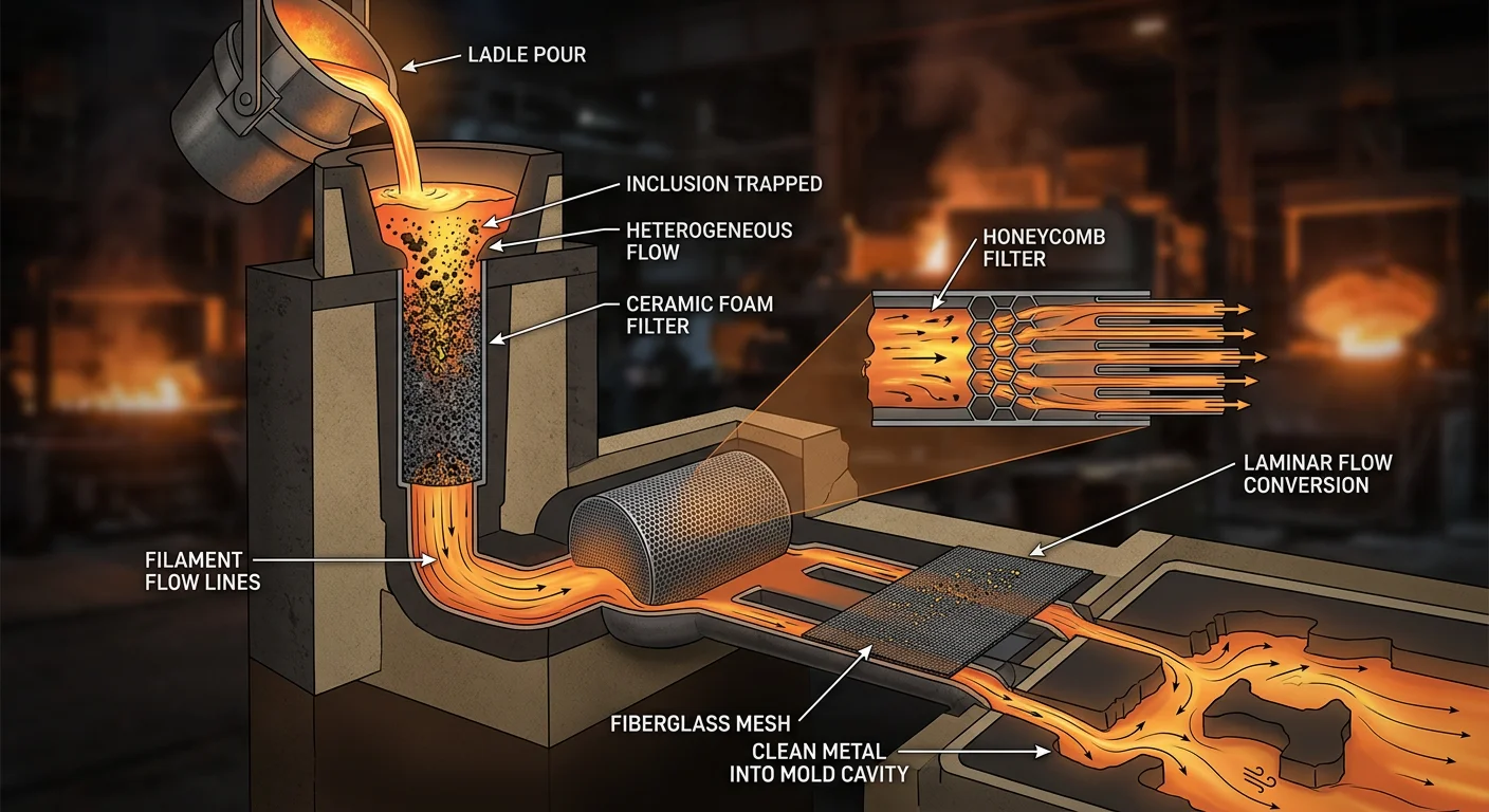
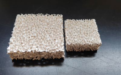
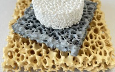
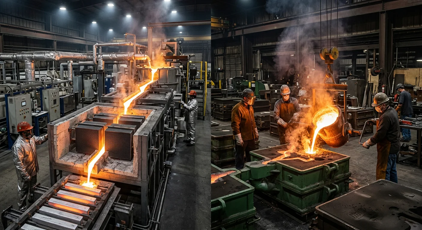
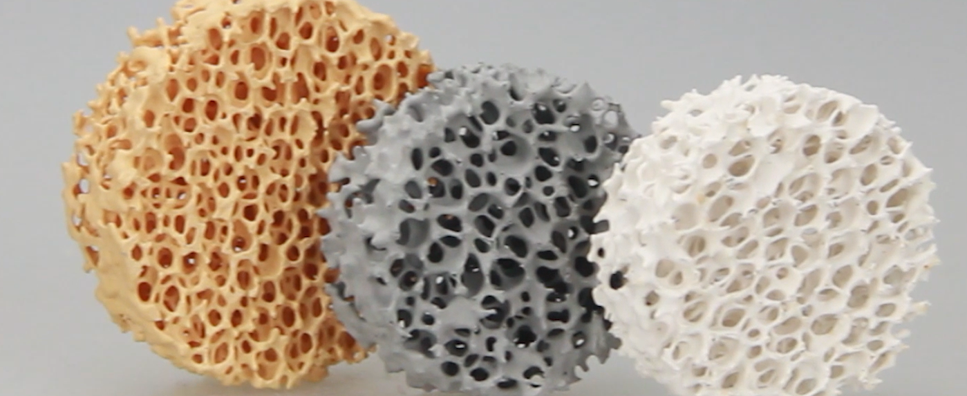
casting filters are porous elements — ceramic foam, Honeycomb ceramic, or Fiberglass mesh — placed in the gating system between the ladle and the mold cavity. They do two things: trap non-metallic inclusions before they reach the casting, and turn chaotic turbulent flow into smooth, steady fill.
Both jobs matter. Inclusions are the obvious target — alumina films, slag particles, refractory debris, dross. But turbulence does just as much damage. Uncontrolled metal speed erodes sand molds, pulls in air, and creates fresh oxide layers mid-pour. A filter tackles both issues at once.
The numbers back this up:
-
Aluminum alloys: ceramic foam filters cut non-metallic inclusions larger than 20–30 µm by 50–80%, based on pore density and gating geometry
-
Steel castings: foam filters pull out around 40% of small inclusions in green-sand molds
-
Scrap reduction: well-matched filtration delivers 5–20% lower scrap rates across critical casting applications
Why Metal Type Determines Filter Choice
Three factors drive the split: pouring temperature, inclusion chemistry, and chemical reactivity of the melt.
Aluminum pours at 680–760 °C. E-glass mesh handles that range fine — its softening point sits around 900 °C. Cast iron runs at 1,300–1,450 °C. That same mesh fails at those temperatures. Iron needs high-silica fiberglass or SiC-based ceramics rated to 1,450 °C, with a softening point near 1,700 °C.
Steel goes even higher — up to 1,700 °C. At that level, zirconia or zirconia-mullite filters are the only options. Other materials crack or break down under those conditions.
Inclusion chemistry adds another layer to the problem. Aluminum melts carry Al₂O₃ films and spinels. Iron carries FeO, silicates, and carbides — these have a direct effect on graphite morphology. Steel carries hard, fine alumina-spinel complexes. Those demand fine-pore, high-strength filters that hold up under thermal shock without fracturing.
No single filter material works across all three metals. The temperature ranges don’t overlap. The chemical environments pull in opposite directions. That’s not a product limitation — it’s just physics.
Filters for Aluminum Casting: Types, Performance Data, and Best-Fit Applications
Aluminum foundries have three practical filter options — and the performance gap between them is real.
Glass fiber mesh, Ceramic foam, and Ceramic honeycomb each sit in a different tier. Your alloy, your cleanliness target, and your current scrap rate will point you to the right one.
Glass Fiber Mesh: The Low-Cost Baseline
Mesh filters are cheap, disposable, and useful — up to a point.
Standard specs: alkali-free glass fiber, ~300 g/m² density, 0.8 mm openings, 0.18–0.35 mm thick. The operating range tops out at 700–800°C, with a softening point near 900°C. That covers standard aluminum casting temperatures without issue.
Mesh works well for Sand casting and permanent mold operations running non-critical Al-Si alloys. General automotive housings fit here too. So do industrial parts where oxide skins and larger dross are the main concern — not fine-micron cleanliness.
It falls short fast. Fatigue resistance, fracture toughness, or sub-80 µm inclusion control on the spec sheet? Mesh hits its ceiling. You’ll need something better.
Ceramic Foam Filters: The Performance Workhorse
Scrap rates still high after switching from mesh? Or are structural mechanical properties on the line? That’s the signal to move to ceramic foam.
Two materials lead the market — Al₂O₃ and SiC — and they serve different needs.
Al₂O₃ foam handles up to 1,200°C with moderate thermal shock resistance. Best fit: high-purity primary aluminum and alloys where zero silicon pickup is a hard requirement.
SiC foam runs to 1,500°C. It handles thermal shock far better. It also wets faster with molten aluminum, which means quicker priming and better inclusion contact from the first seconds of pour. For multi-shift, high-volume lines running 700+ pours per week, SiC is the more durable, lower-maintenance pick.
Filtration efficiency by pore density (Alumina foam):
|
PPI |
Smallest Captured Inclusion |
Filtration Rate |
|---|---|---|
|
20 |
~80 µm |
~78% |
|
30 |
~40 µm |
~85% |
|
40 |
~20 µm |
~88% |
|
50 |
~10 µm |
~92% |
|
60 |
~5 µm |
~95% |
PPI selection by application:
– 10–20 PPI — primary aluminum, large castings, high flow required
– 20–30 PPI — general alloy castings, standard foundry cleanliness
– 30–40 PPI — structural automotive: wheels, suspension arms, chassis components
– 40–60 PPI — aerospace, critical automotive, electronics, thin-wall precision parts
Flow capacity by filter size (aluminum alloys):
– 7″ filter: 22–56 kg/min
– 9″ filter: 25–80 kg/min
– 12″ filter: 50–156 kg/min
Match filter diameter to pour weight. Don’t guess. A size mismatch either starves the mold or lets metal bypass the filter altogether.
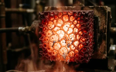
Ceramic Honeycomb and In-Line Plate Filters: High-Volume Precision
Move from batch molds to continuous or DC casting and the filtration setup changes completely.
Honeycomb plate filters mount in refractory cassettes inside launders or filter boxes, positioned upstream of the tundish. They’re built for lines producing aerospace plate, extrusion billet, can stock, and conductor alloys. Standard sizes run from 178×178×50 mm up to 584×584×50 mm, rated to ~1,390°C.
The performance numbers at this tier are hard to ignore:
– ~25–30% improvement in molten aluminum mobility vs. unoptimized gating
– Up to 85% reduction in casting rejection rate with correct sizing
– 10–20% mechanical strength gain from lower inclusion content
Laminar flow drives most of those results. Straight-channel honeycomb geometry cuts out splash entry, lowers entrained gas, and stops the cold shuts and surface laps that cause problems on high-speed continuous lines. Some setups connect directly with in-line degassing units or direct-pour systems like KALPUR, giving full control over gating and feeding.
This tier isn’t for the general job shop. It’s for operations where inclusion count, repeatability, and downstream mechanical certification drive every decision.
Filters for Iron Casting: SiC Foam, Flow Control, and Gating Consistency
Iron foundries don’t struggle with cleanliness the way aluminum foundries do. The real problem is consistency.
Metal velocity, turbulence, operator variation, ladle tilt speed — all of it builds up inside the runner system before the first drop of iron reaches the cavity. A filter doesn’t just strain slag out of the melt. In iron casting, it acts like a hydraulic fuse. It standardizes flow no matter what’s happening upstream.
That’s why SiC ceramic foam is the top choice for gray and Ductile Iron filtration.
Why SiC — Not Alumina, Not Glass Fiber
The chemistry is simple. Iron pours at 1,350–1,500°C. SiC holds up to 1,450–1,560°C. It delivers compression strength of ≥1.2 MPa, open-cell porosity above 80%, and thermal shock resistance that alumina foam can’t match at iron temperatures. It’s also stable against Fe–C melts. No breakdown. No contamination. No reaction products entering the casting.
Glass fiber strainers still appear in low-demand jobs: small grey iron runs, ladle-lip screening on cupola furnaces, cases where stopping large slag chunks is the only goal. But they offer no real hydraulic control. They don’t laminarize flow. They don’t stabilize fill times. The moment thin-wall filling reliability or repeatable mold cycle times enter the picture, foundries switch to SiC foam.
Pore Density by Application
|
PPI Range |
Best-Fit Application |
|---|---|
|
10–15 PPI |
Large grey/ductile iron, high throughput, coarse inclusions |
|
20–30 PPI |
General automotive ductile iron — housings, carriers, 6–30 mm wall |
|
30–40 PPI |
Thin-wall iron (3–6 mm), high-cleanliness requirements |
Finer PPI captures inclusions more tightly — but it also raises pressure drop. At 30–40 PPI for thin sections, you need either more metal head or a larger filter face area. Otherwise fill times drift out of spec.
Placement and Gating Consistency
Where you place the filter matters as much as which filter you choose.
SiC foam mounts vertically, horizontally, or at an angle depending on runner geometry. Three positions dominate in practice:
-
Beneath the sprue — vertical mounting in a print under a tapered sprue; absorbs first-impact turbulence before it spreads
-
In the main runner — horizontal placement between sprue and ingates; standard for medium-to-large grey and ductile iron in green sand
-
At the ingate — smaller filters placed just before thin-section ingates; more common in bonded sand molds, and critical for thin brake components and turbine housings
For DISAMATIC and other vertically parted automatic lines, the setup is different. One filter. Fixed position. Fixed size. Same spec across an entire casting group. The goal is to make the filter — not the operator, not ladle tilt angle, not small head changes — the main variable controlling fill time. Target variation: ±5–10% across the mold cycle.
That’s the hydraulic fuse concept working as intended. At a standard iron head of 400–800 mm, sic filter permeability controls flow rate. Ladle-to-ladle variation of ±100–200 mm in metal height has almost no effect downstream. Flow stays predictable. Pour times stay consistent.
Typical face velocity through the filter: 0.3–0.6 m/s. Go above that range and turbulence creeps back in. Drop below it and misrun risk rises on thin sections.
What Iron Foundries Gain From SiC Filtration
Here’s what the outcome profile looks like for SiC-filtered iron:
-
Slag and inclusion removal: slag, magnesium reaction products, inoculant residues, and sand grains — all captured before the cavity
-
Reduced core wash and sand inclusions: lower jet velocities at the filter exit mean less runner and core erosion
-
Fewer cold shuts and misruns: a laminar flow front across thin sections means less entrained air
-
Scrap reduction: internal foundry data points to 20–50% reductions in inclusion-related defects after SiC filtration is introduced
-
Simplified gating: the filter handles turbulence control, so complex swirl runners and elaborate skim features are no longer needed — fewer components, more direct gating
One point on data: most major suppliers treat detailed pressure-drop and flow-rate curves for specific iron alloys at temperature as proprietary. Public specs cover porosity, PPI range, and operating temperature. The real application-specific design work happens through vendor tools, in-house trials, and targeted fill-time testing. Iron foundries don’t benchmark against aluminum filter curves. The density difference alone — 7.0 g/cm³ vs 2.4 g/cm³ — makes any direct comparison useless. The process logic is different. The filter decision framework has to be different too.
Filters for Steel Casting: Zirconia Foam, High-Temperature Inclusion Control, and Priming Challenges
Steel is unforgiving. Pour it through the wrong filter and you don’t get a second chance — the metal freezes, the filter cracks, or inclusions slip straight through into the casting.
At 1,600–1,700°C, most filter materials don’t survive. Alumina foam tops out around 1,200°C in real service. Glass fiber isn’t even an option. For steel, one material works: zirconia (ZrO₂) foam.
Why Zirconia — And Nothing Else — Handles Steel
The numbers tell the story. Certified ZrO₂ filters operate up to 1,750–1,760°C. Alumina foam fails at 1,200°C. That’s not a small gap — it’s a completely different category.
ZrO₂ filters also deliver better thermal shock resistance and higher hot strength than alumina under real pour conditions. Long-sequence steel pours, high-superheat ladles, interrupted flow mid-fill — alumina softens or erodes under those stresses. ZrO₂ holds.
Commercial specs back up the performance:
-
Foundrymax FM-03: max working temperature ~1,760°C; covers stainless, carbon steel, cast iron, and superalloys
-
Stanford Advanced Materials ZC2328: ≥94% ZrO₂, working temperature ≤1,750°C, 10–60 PPI range
The application map by steel grade:
|
Steel Type |
Typical Casting Temperature |
Filter Requirement |
|---|---|---|
|
Carbon and low-alloy steel |
1,550–1,650°C |
ZrO₂ or ZrO₂-mullite |
|
Stainless and high-alloy (Cr-Ni, tool steels) |
>1,600–1,700°C |
Full ZrO₂ |
|
Manganese steels (Hadfield) |
1,350–1,450°C |
ZrO₂ — hot strength critical for Mn-rich slag |
|
Ni/Co-base superalloys, aerospace steels |
>1,600°C, vacuum cast |
ZrO₂ foam standard |
Inclusion Chemistry in Steel: Why It’s Harder Than Iron or Aluminum
Steel inclusions aren’t uniform. They fall into three groups. Each one needs something a bit different from the filter.
Deoxidation products — Al₂O₃, SiO₂, MnO·SiO₂, Ca-aluminates, TiOₓ — form during killing practice before the pour starts. Reoxidation products — FeO, MnO, mixed oxides, fresh alumina — form during the pour itself. Dissolved elements react with atmospheric oxygen or slag as metal flows. Refractory debris — alumina, silica, MgO particles from tundish linings and nozzle wear — enter the stream through physical contact.
The hardest case is Al-killed steel. Dissolved aluminum reacts hard with FeO, MnO, and SiO₂ in slag and refractories. The reaction pushes inclusions toward hard, angular, Al₂O₃-rich stringers. These stay solid at steel temperatures. They’re abrasive in service and damage both machinability and fatigue life.
To capture those inclusions, you need fine-pore ZrO₂ or ZrO₂-mullite foam at 20–30 PPI. Coarse-pore filtration aimed at large slag droplets won’t do it. The target is small, hard, alumina-rich particles — and ZrO₂ surfaces pull them in. Alumina-rich inclusions bond to ZrO₂ at steel temperatures, which raises capture efficiency. The tradeoff: pore blocking risk goes up in high-alumina-load heats. The fix is increasing frontal filter area, not just raising PPI.
Si-killed or low-Al steels produce softer, glassier MnO–SiO₂ inclusions. These are easier to capture. High-grade alumina or ZrO₂-mullite handles the job at 1,500–1,600°C — full ZrO₂ isn’t always needed.
ZrO₂ foam works best in the 10–300 µm inclusion size range. Coarse refractory chips and slag droplets get trapped by inertial impaction at the filter entrance. ZrO₂’s structural strength stops the channeling or breakthrough that would let those particles through.
The Priming Problem: Where Steel Filtration Gets Complicated
Priming is where steel filtration gets truly difficult — and where filter selection beyond material grade starts to matter.
Priming means filling the foam filter with molten metal until stable through-flow is established. Every second the filter is priming, it’s also absorbing heat. ZrO₂ has high thermal mass — high density, high heat capacity. At low superheat, incoming steel loses temperature faster than it primes. The metal starts to solidify in the leading cells of the filter. That’s chilling by filter — and it cascades fast.
The consequences:
-
Long priming times — delayed fill, inconsistent metal front, turbulence creep
-
Incomplete filling — thin sections that misrun before the filter is fully primed
-
Increased scrap — cold shuts, misruns, and extra gating metal all cut yield
Priming time gets worse as:
– Superheat drops (from 80–100°C ΔT down to 20–40°C ΔT)
– Filter thickness increases
– Steel grade has a wide solidification range or poor fluidity (high-Mn or high-alloy grades are hit hardest)
The practical fix is low-thermal-mass ZrO₂ filter variants — designs with reduced ceramic cross-section, thinner foam walls, and lower bulk density. Same ZrO₂ chemistry, far less thermal mass. The filter reaches steel temperature faster. Metal breaks through sooner. The chill zone at the leading face shrinks.
The difference is measurable. Low-thermal-mass ZrO₂ filters allow pouring temperatures 20–40°C lower while still achieving full priming and fill. That matters for grain size control in near-net-shape carbon steel. It’s also critical for Hadfield manganese steel — narrow feeding windows and poor fluidity mean any priming delay turns into a defect.
Practical rules with low superheat:
-
ΔT ≥ 60–80°C: standard ZrO₂ foam works fine
-
ΔT ≤ 40–50°C: switch to a low-thermal-mass ZrO₂ variant
-
Heavy sections needing fast priming: 10–20 PPI, larger frontal area, pair with a ceramic well to stabilize flow
-
Cut filter thickness where possible — moving from 50 mm to 35–40 mm reduces thermal absorption without losing capture performance
Material Hierarchy and Selection Logic
Not every steel pour needs full ZrO₂. There’s a cost-performance hierarchy worth knowing:
High-grade alumina / alumina-mullite foam — practical ceiling of ~1,450–1,500°C in steel service. Useful for short-contact-time pours, low-superheat scenarios, and Si-killed or low-Al grades where slag is less aggressive. Lowest cost.
Zirconia-mullite foam — the middle option. Better thermal shock resistance and chemical stability than alumina, lower unit cost than full ZrO₂. Covers medium-alloy steels at 1,500–1,650°C. A good fit when alumina pickup must be minimized but full ZrO₂ isn’t justified.
Full ZrO₂ foam — required above 1,650–1,700°C, for high-alloy and superalloy casting, multiple ladle sequences, or any application with severe thermal cycling. Highest cost. Best hot strength and longest service life.
The cost objection to ZrO₂ is real — unit prices run 2–4× alumina foam. So is the counter-argument:
-
Inclusion-related scrap reduced by 20–50% in documented cases
-
Weld and grind rework cut by 20–40%
-
Machining tool life goes up by removing hard alumina stringers from the casting
-
Yield increases of 1–3 percentage points with correctly sized filters paired with low-superheat practice
At those margins, filter cost becomes noise. The scrap rate and finishing labor are the real numbers.
Steel Filter Implementation: Decision Checklist
-
Define deoxidation practice — Al-killed, Si-killed, Ca-treated. This sets inclusion chemistry and minimum filter grade.
-
Select filter material by temperature and inclusion type:
-
Al-killed, T_pour ≥ 1,600°C → ZrO₂ or ZrO₂-mullite
-
Si-killed, T_pour 1,500–1,600°C → ZrO₂-mullite or high-grade alumina
-
-
Evaluate superheat (ΔT):
-
ΔT ≥ 60–80°C → standard ZrO₂
-
ΔT ≤ 40–50°C → low-thermal-mass ZrO₂ variant
-
-
Choose PPI and frontal area:
-
Heavy sections → 10–20 PPI, larger face
-
Thin-wall or precision castings → 20–30 PPI
-
-
Position in gating system — use submerged filter prints, placed as far from the metal free surface as practical. Keep 50–150 mm of head height above the filter to maintain metallostatic priming pressure.
-
Track outcomes — inclusion ratings, misrun frequency, weld/grind labor, tool life, and yield, before and after any filter or superheat change.
Steel filtration isn’t complicated once the variables are clear. Temperature drives material selection. Superheat drives filter design. Inclusion chemistry drives pore density. Get those three right and the ZrO₂ filter does its job: stop inclusions, stabilize flow, and protect the casting from the moment metal enters the Gating System to the moment it solidifies.
Side-by-Side Comparison: Filter Material Selection by Metal Type
Three metals. Four filter materials. One decision that determines whether your castings pass or fail.
The table below matches each filter material to the metal it belongs with — not in theory, but in real production.
|
Filter Material |
Best-Fit Metal |
Max Service Temp |
Inclusion Types Captured |
PPI Range |
Relative Cost |
|---|---|---|---|---|---|
|
Alumina foam (Al₂O₃) |
Aluminum alloys, nonferrous |
~1,200–1,600°C |
Oxides, dross, coarse inclusions |
10–60 PPI |
Low–medium |
|
SiC foam |
Cast iron, ductile iron |
~1,400–1,600°C |
Slag, oxides, sand, mixed inclusions |
10–30 PPI |
Medium |
|
Zirconia foam (ZrO₂) |
Steel, superalloys |
1,600–1,750°C+ |
Fine oxides, refractory debris |
10–30 PPI |
High–very high |
|
Honeycomb ceramic |
Steel, iron, aluminum |
~1,000–1,600°C |
Coarse slag, dross, larger inclusions |
Channel-based |
Low–medium |
Glass fiber mesh is missing from this table for a reason. It softens and loses structural strength before it gets close to molten aluminum temperatures. It belongs in dust filtration. Not in a foundry gating system.
Where Cross-Application Mistakes Happen
The wrong matches cause more damage than the right ones prevent.
Alumina in steel service is the most common error. Alumina foam performs well for aluminum. Put it into a steel pour and the aggressive chemistry erodes the foam surface faster than it can filter. Inclusions slip through. The filter clogs in uneven patches. Service life drops fast.
Zirconia on an aluminum line is the opposite problem — not failure, just waste. The refractory margin ZrO₂ provides above 1,650°C means nothing at 720°C. You pay the cost premium and get nothing back.
SiC pushed into high-superheat steel falls between those two failure modes. SiC handles iron well. In oxidizing, high-temperature steel streams, surface oxidation breaks it down. The thermal and chemical load goes beyond what SiC was built to handle.
The Priority Order for Filter Selection
Procurement decisions can get messy. Use this hierarchy to cut through:
-
Temperature and chemical compatibility — non-negotiable; get this wrong and nothing else matters
-
Inclusion size capture — matched to PPI and target defect threshold
-
Pressure drop — affects fill time and misrun risk
-
Cost — last in line, not first
The cost ranking across materials runs: glass fiber → alumina foam ≈ honeycomb → SiC foam → zirconia foam. That progression tracks closely with operating temperature and chemical aggression. You pay for refractory performance because the metal demands it.
Performance Priorities Differ by Metal: What You’re Optimizing For
Filter selection looks like a material science problem. It’s an optimization problem — and the target shifts depending on which metal you’re pouring.
Each metal has a different hierarchy of concerns. Match your filter to the wrong priority and you’ll get marginal gains at best, defective castings at worst.
Aluminum: Surface finish and porosity come first
For aluminum, the top priority is surface finish. Porosity control comes second. Yield comes third. In that order.
Surface targets vary by application. General automotive structural castings run Ra 3.2–6.3 µm after shotblast. Decorative electronics and EV housings require Ra 0.8–1.6 µm post-machining. To hit those targets, you need to keep small inclusions out of the melt before they transfer through to the surface. That’s why 30–50 PPI ceramic foam is standard for premium Al castings. Not because finer is always better — but because the inclusion size distribution must stay below 50–100 µm for high-cycle fatigue and cosmetic acceptance.
Porosity follows the same logic. Moving from no filter to 20–30 PPI foam in Al sand casting cuts oxide inclusion counts by 50–70% and reduces porosity in heavy sections by 30–50%. The tradeoff is pressure drop. Very fine filters (40–50 PPI) can reduce yield by 3–10 percentage points versus 20 PPI. So PPI selection always comes down to a cost-of-scrap versus gating-head calculation.
Iron: Consistency outranks cleanliness
Iron foundries optimize for something aluminum foundries don’t often mention: repeatable fill time. Tolerances of ±5–10% on pour time and ±10–15°C on temperature are the real KPIs — not inclusion ppm.
That’s why iron filter placement logic inverts aluminum practice. In aluminum, filters sit near the ingate to protect the cavity surface. In iron, filters sit at the sprue base or early in the runner, acting as the hydraulic choke. The filter controls fill rate. Everything else follows from that.
Steel: Inclusion control at a different standard
Steel puts non-metallic inclusion control above everything else — including yield. Total oxygen targets of 15–30 ppm for high-spec cast steels, with inclusion ratings to ASTM E45 A/B/C/D ≤ 1.5–2.0, are not cosmetic requirements. These are fatigue life and fracture toughness requirements.
The downstream cost makes the economics clear. Reducing total oxygen from 80 ppm to 40 ppm increases carbide tool life by 20–50% in machining operations. Rework and heat-treatment cycles on steel castings are expensive. So foundries often accept lower metal yield — more risers, more conservative gating — to improve soundness and machinability. The tradeoff pays off.
Pore Size (PPI) and Filter Structure: How to Match Specification to Process Requirement
PPI looks simple on paper. But stand in front of a scrap bin after a failed pour, and that number takes on a different weight.
Pores per linear inch — that’s all it measures. Behind that single number, though, sits a chain of physical consequences. It starts at inclusion capture rate and ends at misrun frequency. Get it right and the filter does its job without a fuss. Get it wrong and no amount of gating redesign saves you.
What PPI Controls
The real physics lives in the cell-to-throat relationship.
At 10 PPI, each cell is about 2.5 mm across. The pore throat — the narrowest passage metal travels through — measures 0.75–1.25 mm. Scale up to 50 PPI and that throat shrinks to 0.15–0.25 mm. That’s not a small refinement. That’s a completely different filtration regime.
Everything shifts with it:
-
Sieving cutoff: particles larger than the throat diameter get captured by the physical barrier. Smaller ones depend on surface adhesion and how twisted the flow path is.
-
Pressure drop: finer PPI means smaller throats, higher resistance, and less metal passing through per unit time.
-
Throughput capacity: a 10 PPI filter in clean aluminum carries over 3,000 kg before choking. A 50–60 PPI filter handles 200–400 kg before hitting the same threshold.
That throughput drop isn’t a reason to avoid fine filters. It’s a reason to size them right.
Foam vs. Honeycomb: Two Different Jobs
Ceramic foam and honeycomb ceramic work in fundamentally different ways.
Foam is a tangled 3D network. It has high internal surface area — 300–600 m²/m³ — and captures inclusions deep along its struts, not just at the surface. The flow path twists and turns. Inclusions of different sizes hit different surfaces at different angles. The filter also tightens itself over time. As larger pores block, smaller particles that slipped through earlier start getting caught. Efficiency goes up. Pressure drop goes up with it.
Honeycomb runs parallel channels — square or hexagonal cells, laminar flow, low and steady pressure drop. Its internal surface area per unit frontal area is lower than foam. It gives up some depth capture, but it makes up for that with consistent hydraulic behavior. Fill times stay predictable. That matters on high-volume permanent mold and continuous casting lines where flow rate is the variable you’re controlling.
Where each structure fits:
-
High-spec aluminum sand or investment castings → 30–50 PPI foam, for broad inclusion size distribution and depth capture
-
High-volume aluminum permanent mold or HPDC → honeycomb or 10–20 PPI foam, to preserve throughput
-
Steel ingate filtration → 10–30 PPI foam for deep capture; honeycomb where head pressure is high and gating is simple
-
Heavy-section iron at high pour rates → honeycomb or 10–15 PPI foam in sprue or runner
-
Thin-wall ductile iron gear housings → 20–30 PPI foam in runner or ingate, sometimes combined with honeycomb upstream
Matching PPI to Process: The Four-Step Logic
Skip the catalog. Work through the process.
Step 1 — Define alloy and charge cleanliness. Rotary furnace aluminum or cupola iron with visible dross? Start at 10–20 PPI. Degassed aluminum or ladle-treated ductile iron? Move to 20–30 PPI. Calcium-treated steel or aerospace aluminum? You’re in 30–50 PPI territory.
Step 2 — Map quality target to inclusion size. Non-critical iron castings tolerate inclusions above 200 µm — 10–20 PPI coversthat. Automotive aluminum structural parts have a defect threshold of 50–150 µm — that points to 30–40 PPI. Aerospace aluminum or stainless steel targeting below 50–80 µm needs 50 PPI, or a staged setup: a 20 PPI pre-filter first, then a 50 PPI final filter.
Step 3 — Check flow and head. Flow velocity through the filter above 15–20 cm/s at your required pour time? Drop to lower PPI or increase filter face area. Available head under 100–150 mm — low Pouring Basin, compact gating — stay below 50 PPI on high-volume castings. The math: required filter area (cm²) = flow rate (kg/min) ÷ specific filtration rate. At 30 PPI in aluminum, that rate runs 4–8 kg/min·cm². At 50 PPI, it drops to 2–4 kg/min·cm².
Step 4 — Account for inclusion load. High dross burden blocks a 50 PPI filter in less than half the metal volume a 30 PPI filter handles under the same conditions. Staged filtration solves this. Put a coarse 10 PPI filter upstream to catch bulk inclusions. Then use a fine 30 PPI filter near the ingate for final cleanup. This setup extends service life on dirty melts without giving up cleanliness at the cavity.
Placement Compounds PPI Selection
Filter position changes what PPI can actually deliver.
Upstream positions — pouring cup, sprue — face the heaviest inclusion load and the most turbulent entry flow. Coarse filtration, 10–15 PPI, makes sense here. It catches bulk slag and dross before pressure drop builds. Push PPI too fine at this position and you risk clogging early.
Mid-runner placement sees less initial load. Inclusions have already started to separate. Medium PPI — 20–30 — works well here. Flow arrives at the filter face in a more stable state.
Near the ingate, inclusion load is lowest. Flow velocity is lower too. This is where 30–50 PPI does its best work — fine capture, low clogging risk, and close enough to the cavity that captured inclusions stay where they are.
One caution: a filter that becomes the system choke at the ingate changes the fill pattern. The metal front slows downstream. In thin-wall sections, that raises cold shut risk. Size the filter to control turbulence — not to cut flow below what directional solidification needs.
How to Select the Right Casting Filter: A Decision Framework Across All Three Metals
Four decisions. Made in sequence. That’s the whole framework.
Most filter selection errors trace back to skipping one of those steps — or running them in the wrong order. The framework below fixes that.
Step 1: Temperature First — It Eliminates Most Options Fast
Pouring temperature is your first filter. Not a metaphor. A hard rule: a material that can’t survive contact with your melt is off the list. End of discussion.
-
≤800°C (aluminum, magnesium) → glass fiber mesh or alumina foam
-
800–1,400°C (copper alloys, some iron) → mullite or SiC foam
-
1,400–1,600°C (gray/ductile iron) → SiC foam; alumina-mullite for borderline cases
-
≥1,600°C (steel, superalloys) → zirconia foam, no exceptions
Step 2: Inclusion Type → PPI and Structure
Temperature narrows your material shortlist. After that, inclusion chemistry and criticality set your pore density:
-
Coarse slag, bulk dross → 10–20 PPI or 1–3 mm mesh openings
-
Fine oxide films, sand fines → 30–50 PPI foam (20–30 PPI for steel, to avoid priming failure)
-
Aerospace or ultra-clean targets → 40–60 PPI plus upstream degassing; often dual-stage
Step 3: Process Format and Placement
Filter format follows your casting process — not the other way around.
Sand molds take square foam in the runner. Place it close to the ingate. You need at least 2–4× filter thickness of metal head above it to guarantee priming. Permanent mold aluminum lines use mesh cut-to-shape at the inlet. For wheel and structural applications, ceramic foam in a filter bowl is the standard choice. Steel gating systems need ≥100 mm of head above the filter. Drop below that, and priming stalls before the cavity fills.
One rule holds across all three metals: no bypass. A filter with a loose fit is no filter at all.
Step 4: Performance Priority → Final Grade and Cost Level
This is where economics enter — last, not first.
Yield and cost are your top concerns? Use 10 PPI SiC foam in iron runners. It cuts inclusion-related scrap by 30–60%. That’s your baseline. Cleanliness is critical — aerospace aluminum, hydraulic steel? Go to 30–50 PPI. Add ladle refining upstream. The filter becomes the final barrier, not the primary one. Consistency drives the call on high-volume automotive lines? Move to a coarser PPI with a larger face area. A 70×70 mm 20 PPI filter outlasts a 50×50 mm 30 PPI filter on dirty heats. Cleanliness stays equivalent.
The cost upgrade rule is simple: one scrapped casting that costs more than 20–50× the filter price means the upgrade pays for itself.
Conclusion
Aluminum, iron, and steel behave in different ways inside the mold. Each metal needs its own filtration approach — not a shared one.
The right filter is not a small detail. It’s the line between a clean, defect-free casting and a scrapped pour that costs you time, material, and margin.
The path forward is straightforward:
-
Match your filter material to your metal’s heat level and chemical behavior
-
Align PPI spec to your actual flow needs
-
Stop treating filtration as an add-on to gating design
Now put it to work. Audit your current filter choices against the data in this article.
Running SiC on your aluminum line? There’s a better match. Relying on alumina for steel at 1600°C+? You’re leaving performance on the table.
Aluminum, iron, and steel casting filters are not interchangeable. Foundries that treat them as the same thing pay for it — with every single heat.