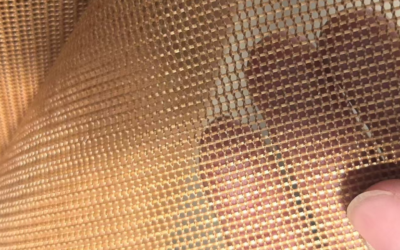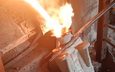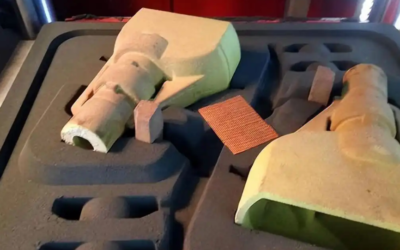
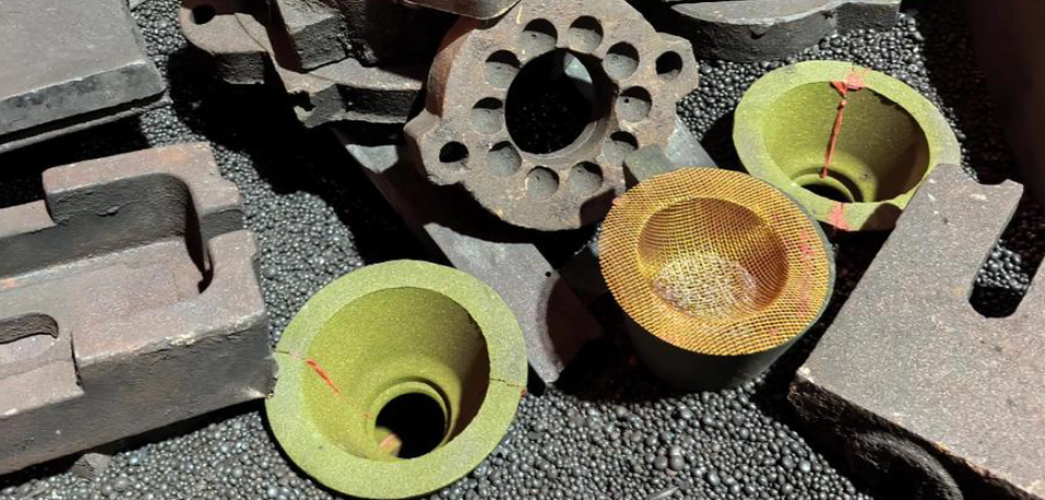
When a filter cracks mid-pour, molten metal bypasses filtration, carrying slag and inclusions straight into your gating system and scrapping the casting before it even solidifies. If you’ve pulled a ruptured glass fiber mesh filter cloth out of your sprue and wondered whether to blame a bad batch, a pouring temperature mismatch, or your gating design, the answer rarely comes down to one variable. These failures typically stem from thermal shock, flow velocity, improper seating, pre-existing damage, or the wrong mesh for your alloy. This guide walks through each root cause alongside real breakage patterns, so you can diagnose what happened on your floor and fix it before it costs you another heat.
Thermal Shock and Temperature Incompatibility
Heat moves through a filter unevenly, which is how cracking starts. The metal-contact side heats immediately while the back face lags behind, setting up a steep temperature gradient across the thickness. That gradient causes differential expansion and tensile stress, leading to cracks, fragments, or clogged pores. A cold filter can even freeze the first slug of metal entering it, choking flow before the pour gets underway.
Aluminum is unforgiving, typically arriving at 720–760°C. Dropping a room-temperature ceramic filter straight into that stream invites severe thermal shock. The risk begins well before direct contact, too. Heating a filter from room temperature past 400°C in under 10 minutes creates thermal-shock damage before molten metal ever touches it.
A safer preheat ramp:
– 0–10 minutes: 100–200°C
– 10–20 minutes: 200–500°C
– Final 10–20 minutes: 700–800°C
– Total controlled preheat: at least 30 minutes before aluminum contact
Standard glass-fiber or low-temperature filter constructions should not face temperatures above 800°C unless your supplier specifies a high-temperature ceramic formulation. Treat the 20-minute exposure figure as a process-control benchmark rather than a fixed limit. The actual failure point depends on binder chemistry, fiber composition, porosity, and the velocity of molten metal hitting the filter.
Excessive Metal-Flow Impact and High Pouring Velocity

Drop height causes the damage here. Pour height and filter velocity follow $v=\sqrt{2gh}$, so every 10 cm added to ladle height drives up both flow speed and dynamic pressure. That stream hits the center of the filter first, where impact pressure scales with $p\approx\frac{1}{2}\rho v^2$. The center pores quickly clog with metal, inclusions, and oxide film, spiking local back-pressure. This triggers a textbook failure sequence where the center loads up, the supported edges hold firm, and the middle tears out.
In Ceramic foam Filters, failure comes from bending stress, shear, and thermal shock acting together. The center deflects under impact while the supported edge resists, generating tensile stress across the back face. Once a crack propagates, the filter either shatters or opens a bypass channel straight into the casting.
Keep direct-pour drop height under 300 mm. If you cannot avoid direct impingement, step up to thicker filters or higher-strength mesh specs. High velocity also shifts filters out of position, splashes unfiltered metal over the top edge, and lets raw metal bypass straight into the mold cavity. For aluminum work, maintain a stable 30–50 mm metal level above the filter. If that level drops below 20 mm, air pulls into the stream and ruins the filtration.
Insufficient Support and Poor Installation Fit
A filter rarely fails on its own. Most cracks start at the seat. If the filter print in your Gating System isn’t level, continuous, and free of debris, the filter sits unevenly from the start, well before metal ever touches it.
Common seating defects that cause breakage:
– Uneven seat angle: keep print tilt under 5°. Anything steeper concentrates the load onto one edge.
– Point-contact support: filters need continuous contact across the entire bearing edge. Resting on a few high spots leaves gaps that let the filter flex and crack under metal pressure.
– Oversized or undersized fit: forcing a filter into a tight print cracks it on insertion, while a loose filter shifts during the pour and opens a bypass gap.
– Debris or casting flash: any raised spot on the print acts as a fulcrum, snapping the filter the instant molten metal hits it.
Check seat flatness with a straightedge before every setup. It takes thirty seconds and saves a heat.
Mechanical Damage and Pre-Existing Cracks
Most broken filters were already damaged before they hit the sprue, even if you couldn’t see it. Shipping vibration, a dropped crate, or stacked pallets leave hidden micro-cracks, chipped edges, corner defects, and slight deformation in glass fiber mesh filter cloth. None of it shows at room temperature. All of it becomes a stress concentration point the moment molten metal arrives. Pre-existing damage propagates through four stages: shipping, handling, manufacturing, and service. Cracks never start at random; they always begin at geometric discontinuities or peak-stress zones.
What this looks like on the floor:
– A chipped edge cuts the load-bearing cross-section, so the filter fails well below rated strength.
– A pre-cracked filter sheds ceramic fragments into the casting under thermal shock, causing inclusions.
– Bright metal crack lines on the filter surface, localized erosion, and metal frozen against the box wall instead of passing through pores show bypass through a hairline fracture that existed before the pour.
Inadequate Sealing and Bypass Issues
A gap you can barely see is enough to ruin a pour. A 1 mm clearance around a filter’s edge lets molten metal skip the mesh, carrying unfiltered inclusions straight into the casting. The filter itself often looks undamaged after the pour, yet the casting shows the same defect levels you would expect if no filter had been used.
What bypass looks like on the floor:
– Continuous or partial gaps between the filter and the filter box, gate pocket, or refractory cavity
– Metal channeling along the filter’s outer walls instead of passing through the pores
– Undersized filters or mismatched box dimensions creating a path of least resistance
– Erosion along filter box edges, refractory fibers, and side walls where bypass flow runs faster than metal moving through the mesh
One supplier reported that a thin bypass channel in the filter box cuts theoretical filtration efficiency by about 30%, and a visual inspection will not catch it. Extended pouring times and turbulence make this worse. Over time, heat and sustained flow widen mesh pores or wash away filter material, pushing inclusion levels in later-poured castings higher than earlier castings from the same heat.
Why Dimensional Tolerance Drives Bypass Risk
Sizing mismatches cause most bypass problems. Ceramic foam filter tolerances typically run at +0.5/-1.5 mm for dimensions under 99 mm, and +0.5/-2.5 mm for larger sizes. Standard industry guidance targets a filter-to-box fit within ±1-2 mm, though your target depends on supplier tolerance, seal compression rate, and pouring temperature. Some aluminum filter plates carry tolerances as wide as ±3 mm with a thickness of 50±2 mm. Because suppliers do not follow a uniform standard, ordering based on nominal dimensions alone creates problems on the floor.
What oversized or undersized filters do:
– Undersized filter: Widens the perimeter gap and opens a continuous bypass channel, destroying filtration efficiency even when the mesh stays intact.
– Oversized filter or tight cavity: Crushes edges, cracks corners, warps the filter, or leaves sections unsupported, generating ceramic inclusions when metal strikes the mesh.
– Poor cavity flatness: Uneven corner heights or debris on the seat seal one side while leaving the other open, causing uneven erosion and unbalanced mechanical load across the filter.
Sealing Material and Installation Practice
Proper sealing does not take brute force. You need a continuous wrap around the filter perimeter using compatible ceramic fiber paper, fiber wool, expanding ceramic fiber pads, or refractory sealing paste matched to your alloy’s chemistry and pouring temperature. The wrap must seal the corners tightly without overlapping seams that could form new channels. In high-temperature or extended pours, expanding fiber pads work best because they swell to close micro-gaps as the assembly heats up.
Before every pour:
– Clear dust, loose refractory, debris, and flash from the filter box.
– Measure filter length, width, thickness, and chamfer, and verify there are no cracks, through-holes, closed pores, or chipped edges.
– Press sealing material firmly against the filter perimeter, keeping it clear of the active filtration area.
– Place the filter level, centered, and fully supported. Never force or tap it into place to close a gap.
– Check for shifting, warping, or tilt after mold assembly, and confirm that no visible gaps show along the edges.
– Inspect the seal on every mold before pouring; rebuild it immediately if the refractory flakes, the box chips, or the pad shifts out of position.
Avoid over-constraining the filter when trying to eliminate bypass. The goal is closing the gap without locking a brittle ceramic mesh down rigid. Apply light, even compression on all four sides rather than pinning down a single corner. Leave controlled room for thermal expansion with compressible or heat-expanding fiber seals instead of wedging rigid refractory blocks against the filter body. Tapered inlet designs, elastic fiber pads, or gasket-style seats work well because the tooling holds the filter in place while the fiber pad handles the gap.
Cracked corners, crushed edges, or visible warping after assembly point to over-constraint, an uneven cavity, or excessive interference fit rather than a defective filter.
Field Controls Worth Setting Up
Track filter length, width, thickness, chamfer, and edge condition for every batch. Check multiple measurement points on larger filters instead of checking only two edges. Inspect the filter box internal length, width, depth, flatness, corner heights, and seal groove continuity as part of your standard setup. Set a maximum allowable perimeter gap as your release criterion. If you lack direct supplier data, start with a conservative threshold: treat any through-gap over 1 mm as an immediate stop-point, then calibrate using trial-pour sectioning and inclusion checks.
When you suspect bypass in a finished casting, inspect the spent filter edges for erosion patterns, check whether the sealing pad washed out, and examine the box corners for damage. Note whether sand or slag defects cluster at the start or end of the pour. This distribution will confirm if the issue stems from a seal failure instead of defective filter media. Choosing a filter system engineered for consistent fit, like FoundryMax‘s glass fiber mesh filter cloth, removes most of this guesswork from the process.
Incorrect Filter Selection for Alloy and Process Parameters
Match the filter to the alloy before worrying about mesh size or PPI, yet foundries frequently skip this step. Sizing glass-fiber mesh filter cloth on melting point alone, or grouping aluminum and iron under a single spec, sets up failure before the pour even starts.
Alloy temperature windows: – Aluminum and Al-Si alloys: Filtration runs at 700–800°C, where standard glass-fiber mesh holds up. Push past 800°C or extend contact time beyond ~20 minutes, and the mesh softens or collapses. – Gray and Ductile Iron: Pouring temperatures hit 1300–1450°C, which destroys glass fiber. Use SiC Foam ceramic rated for continuous service at 1500–1560°C. – Carbon and low-alloy steel: Pours at 1550–1620°C require ZrO₂ ceramic rated to 1700–1760°C. Al₂O₃ or glass fiber lacks the thermal margin and will erode or deform. – Stainless steel: Pours run 1580–1650°C and demand ZrO₂ grade, with chemical compatibility and contact time verified beforehand.
Keep at least a 50°C buffer between the filter’s rated temperature and the pour temperature.
Mesh and PPI selection beyond alloy type: – Glass-fiber mesh sizes range from 0.8×0.8 mm up to 2.5×2.5 mm, with 1.5 mm serving as a sensible starting point without cleanliness data. – ceramic foam PPI: 10–20 for high flow, 20–30 for general castings, and 30–40 for thin-wall or high-cleanliness work. – Thickness runs 0.18–0.35 mm for glass fiber and 30–100 mm for ceramic foam.
Diagnose in order: alloy and temperature grade first, filtration area and flow rate second, mesh or PPI last. Dropping to a finer mesh without fixing a temperature mismatch trades inclusion defects for misruns and cold shuts.
Excessive Filtration Load and Clogging-Induced Rupture
Pores clog from the inlet face inward, and the pressure behind that blockage is what tears the filter apart. Oxide films, slag, and refractory fragments plate onto the entry surface first. They form a “filter cake” that chokes off open area with every second of pour time. As that opening narrows, upstream pressure climbs while downstream flow drops off, delaying mold fill. Once that pressure differential exceeds the ceramic matrix’s flexural strength, the filter cracks, punches through, or shatters completely.
PPI and retention tradeoffs:
– 20 PPI retains ~80 μm inclusions
– 30 PPI retains ~40 μm
– 40 PPI retains ~20 μm
– 50 PPI retains ~10 μm
– 60 PPI retains ~5 μm
Finer mesh catches smaller inclusions, but it clogs faster under heavy slag loading. Your highest risk comes when fine PPI, undersized filtration area, high pour rate, dirty metal, and low pouring temperature all hit at once.
Sizing the filter correctly: Calculate average flow as $Q_m = M/t_f$, then size the area using $A_f \geq Q_m / q_{allow}$, pulling allowable flux from supplier data rather than geometry alone. Engineering practice targets a filtration area 3–5x the downstream choke area. A 229×229×50 mm ceramic foam filter typically rates 25–80 kg/min; a 305×305×50 mm unit runs 50–156 kg/min. Raising casting weight 50% without extending fill time demands roughly 50% more filter area; swapping to a finer mesh will only choke the pour.
Flow velocity benchmark: keep metal velocity through the filter around 0.3–0.6 m/s for gravity Sand casting. Exceeding that range calls for more filter area or a slower pour rate.
Cold-metal clogging feedback loop:
Low-superheat metal freezes against cold pore walls on contact. Smaller pores, thicker filters, and slower flow all speed this up. Once part of the structure freezes shut, the remaining channels must carry the extra flow. That surges local pressure and triggers more freezing, driving a cycle that ends in rupture. Preheating filters at least 200°C above ambient and holding pour temperature 50–80°C above liquidus for steel breaks this cycle before it starts.
Moisture Contamination and Improper Storage
Water hiding inside a mesh filter stays invisible until the pour starts. Over weeks in storage, glass fiber and Ceramic foam filters absorb ambient moisture, which weakens bond structures and loosens ceramic particles. Nothing shows at room temperature. The failure happens the moment that trapped water meets 700–760°C aluminum and flashes into steam. If pores or coatings restrict the steam’s escape, internal pressure cracks the filter, blows edges off, or shatters it outright. Common signs include breaks at mesh cross-points, enlarged pore openings that let inclusions through, and blistering or sudden rupture on contact with molten metal.
Storage benchmarks worth enforcing: – Relative humidity below 50% RH; 30–40% RH for high-value or long-term stock – Preheat Mesh filters to at least 400°C before use – Keep original sealed packaging intact until installation – Store on covered, dry racks away from floors, wash areas, furnaces, and condensation surfaces – Never stack weight on filters, and prevent freeze/thaw cycles on damp batches
|
Storage Condition |
Risk |
Production Result |
|---|---|---|
|
<50% RH, sealed |
Stable |
Consistent filtration |
|
50–70% RH, weeks+ |
Bond degradation |
Cracking, blistering on contact |
|
>70% RH or condensation |
Severe moisture uptake |
Mesh fracture, fragment contamination |
|
Frozen/thawed damp stock |
Trapped moisture expansion |
Sudden breakage during preheat or pour |
Under dry, covered conditions, ceramic Foam filters have a 2-year shelf life. FoundryMax’s SiC and Glass fiber mesh filter cloth hold up just as well when kept dry and away from oil or chemicals. Inspect any batch exposed to high humidity before line use. Isolate filters that show cracks, chips, or discoloration, and dry them to supplier specifications before preheating. Never load cold filters into molten metal.
Diagnostic Guide: Matching Breakage Patterns to Root Causes
A fragment in your sprue tells you what went wrong. Where the crack starts and how it spreads points to the cause long before you run a metallurgical test. Use the table below as a first-pass field diagnostic.
|
Breakage Pattern |
Likely Root Cause |
Field Evidence |
Verify First |
|---|---|---|---|
|
Crack before first metal contact (during preheat or seating) |
Preheat ramp too fast; pre-existing shipping damage |
Fresh, brittle fracture; little deformation; clusters within one batch |
Preheat log, supplier cert, batch inspection records |
|
Center rupture, edges intact |
Excessive drop height, flow velocity, or clogging back-pressure |
Crack radiates outward from the middle; supported edges unaffected |
Pour height, metal flow rate, PPI rating, filtration area sizing |
|
Corner or edge crack |
Seating defect, oversized/undersized fit, debris on the print |
Crushing or chipping concentrated at one edge; uneven contact marks |
Seat flatness, filter-to-box tolerance, print cleanliness |
|
Erosion along the perimeter, filter body otherwise sound |
Sealing gap or bypass channel |
Channeling marks on outer wall; metal frozen against box instead of mesh |
Seal pad condition, measured gap, cavity flatness |
|
Buildup then rupture, mold underfills first |
Filter cake clogging, PPI/area mismatch |
Debris plated on inlet face; upstream pressure rose before failure |
PPI selection, flow velocity (target 0.3–0.6 m/s), filtration area |
|
Sudden shatter, fragments scattered, no obvious prior damage |
Trapped moisture flashing to steam |
Breaks at mesh cross-points; blistering on contact |
Storage humidity records, preheat temperature log |
Three steps before you touch the ladle again:
-
Isolate and preserve. Stop the pour, photograph the failed filter in place, and record crack direction, length, and discoloration before removing anything.
-
Measure against a baseline. Compare wall thickness, mesh pore size, and fit tolerance against an unfailed filter from the same batch and against a known-good reference piece.
-
Change one variable at a time. Adjust the preheat ramp, seal pad, or pour height one by one, then re-pour and inspect. Stacking fixes hides what worked.
FoundryMax’s technical team helps foundries isolate whether an issue comes from material defects, improper fit, or process overload, pressure-testing the current setup before switching filter specs blind.
Prevention Checklist and Best Practices for Foundry Operations
Most filter failures trace back to a skipped checklist step. Manage every pour across five checkpoints: specification, storage, preheat, installation, and pouring control.
Before installation:
– Verify alloy compatibility, PPI, dimensions, and flow capacity against your approved SKU.
– Reject any filter with cracks, chipped edges, blocked pores, or strut damage—hairline defects fail under thermal shock.
– Confirm ladles, runners, and filter chambers are free of sand, oil, and moisture.
– Log the supplier, batch, preheat temp, pour temp, and casting outcome for every mold.
Storage: Keep filters in their original packaging in a dry, climate-controlled room. Use FIFO rotation, quarantine anything dropped or wet, and bake out filters exposed to humidity before use. Never reuse ceramic Foam Filters; trapped inclusions and built-up thermal stress raise the risk of failure on a second pour.
Preheat and installation: Follow supplier heat ramps (150–300°C for ceramic, 200–300°C for iron and steel). Seat filters with full perimeter support and avoid point loads.
Replace the filter immediately if it takes an impact, shows pore blockage, cools mid-pour, or the pressure drop rises 10–15 psi above baseline.
Track defects for two weeks; one foundry cut scrap from 4.19% to 1.90% this way. FoundryMax builds filters to hold up against each checkpoint on this list.
Product Selection Guide: Choosing the Right Filter Media for Your Alloy
Base your choice between mesh and ceramic foam on what your casting needs to survive.
Fiberglass mesh works by surface straining. It is the practical choice for routine aluminum, iron, copper, and small-scale steel parts where unit price matters more than depth filtration. High-volume orders run $0.05–$0.20 per piece, while high-silica iron filters reach up to $0.98. Mesh openings span 0.8×0.8 mm to 2.5×2.5 mm.
Ceramic foam traps inclusions throughout a tortuous 3D path. That internal depth justifies the higher purchase price on structural aluminum, high-purity alloys, and safety-critical parts.
|
Alloy |
Media |
PPI/Opening |
|---|---|---|
|
Aluminum, standard |
High-silica mesh |
0.8–2.5 mm |
|
Aluminum, structural/premium |
Alumina foam |
10–30 PPI |
|
Gray/ductile iron |
SiC foam or mesh |
10–20 PPI |
|
Carbon steel |
Zirconia foam |
1.0–2.7 kg/cm² load |
|
Stainless/high-temp |
Zirconia foam |
1.0–4.0 kg/cm² load |
Max-rated temperatures: Al₂O₃ 1,250°C, SiC 1,560°C, ZrO₂ 1,760°C.
Look beyond unit price. Factor bypass inclusions, blockage, and scrap into your cost per conforming casting—that is where cheap mesh often loses out to properly-specced foam.
Conclusion

Fiberglass mesh filter breakage rarely happens by accident. It is almost always a traceable chain reaction between thermal shock, flow velocity, installation fit, and material compatibility with your specific alloy. Foundries that solve this problem treat gating system filter placement and pouring temperature control as a single engineering decision.
If you are fighting recurring casting defects from filter failure, do not rely on swapping brands and hoping for improvement. Pull a failed filter, match the crack pattern against the diagnostic guide above, and fix the root cause—whether that is storage humidity, mesh size mismatch, or an unsupported gating cavity.
FoundryMax engineers can help you match filter media to your alloy, flow rate, and pour profile. A filter that survives your process is worth far more than a cheap one.