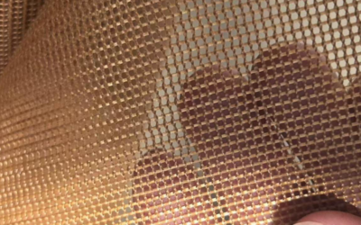
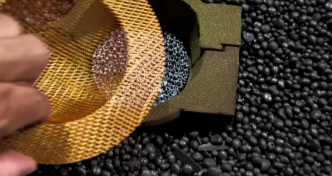
A single mismatched spec on your fiberglass mesh Filter—an opening size 20 microns off, a coating that can’t hold up to your pouring temperature—can turn a smooth casting run into a scrap-rate headache. Most foundry buyers know Mesh Filters matter, but far fewer suppliers explain what’s adjustable versus what’s fixed by manufacturing constraints. That gap is where costly assumptions creep in.
This guide breaks down every parameter you can specify, including mesh filter opening size, filter thickness specification, glass fiber type for casting filter, resin coated Fiberglass mesh options, and Carbonized mesh filter treatments, along with how each choice ties back to your alloy, pour rate, and flow requirements. You’ll also get a practical look at dimensional tolerance expectations, batch consistency benchmarks, and what a legitimate sample approval process should look like before you commit to volume orders.
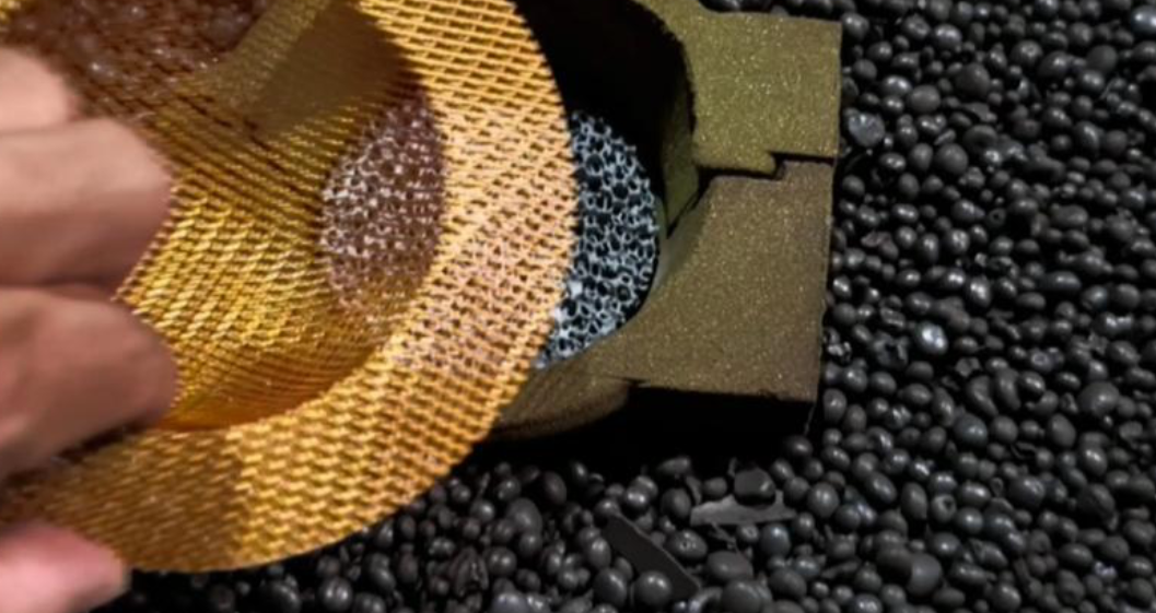
Material Grade & Fiber Composition: Choosing the Right Base for Your Casting Process
Not every fiberglass mesh filter is built from the same fiber. The SiO2 content in the base material decides how much heat it can take, what alloys you can use it with, and where your cost lands. Get this wrong, and you’re either overpaying for capability you don’t need or underspecifying for a metal that will melt straight through your filter.
Standard Alkali-Free E-Glass (58%–65% SiO2)
This is your workhorse for aluminum casting filter applications. Alkali-free E-glass fiberglass fabric won’t alter your aluminum’s chemistry during pour. That matters for slag removal and oxide inclusion capture. Working temperature typically sits at 700–800°C, with roughly 10 minutes of sustained working time before degradation. It’s a cost-effective, general-purpose choice for high-volume aluminum production. If you’re running standard alloy castings without exotic temperature demands, this is your baseline material grade for casting filter specs.
High-Silica Fiber (≥96% SiO2)
For molten iron, molten steel, and copper filtration, you need a different base entirely. high-silica fiberglass, coated with refractory material, handles 1000–1200°C working ranges. Some formulations extend to 1450°C or beyond. It costs more than standard E-glass but is cheaper than Ceramic foam Filters while holding structural integrity under extreme heat.
Quick selection logic:
– 700–800°C, aluminum → Standard E-glass
– 1000–1200°C+, iron/steel/copper → High-silica (≥96% SiO2)
Mesh Opening Size: Matching Hole Dimensions to Flow Rate Requirements
Pick the wrong opening size and you’re stuck choosing between two bad outcomes: a clogged filter that stalls your pour, or a loose mesh that lets inclusions straight through. There’s no universal “right” number—only the right number for your casting.
Standard mesh filter opening size options for aluminum castings run 0.8×0.8, 1.0×1.0, 1.2×1.2, 1.5×1.5, 2.0×2.0, and 2.5×2.5 mm. In mesh count terms, that’s roughly 2.5mm≈8 mesh, 2.0mm≈10 mesh, 1.5mm≈12 mesh, and 1.0mm≈14 mesh.
The core tradeoff: smaller openings capture more inclusions but create higher pressure drop, faster clogging, and slower throughput. Larger openings flow faster and resist clogging but let more debris pass. Never pick based on hole size alone—factor in pour rate, inclusion size, metal temperature, and effective open area of the filter surface.
Three Practical Selection Tiers
-
1.0×1.0 mm — Thin-wall precision parts, decorative castings, high surface-finish requirements. Accepts higher pressure drop for better inclusion control.
-
1.5×1.5 mm — General-purpose castings, automotive wheels, standard production runs. The safest default starting point for most foundries.
-
2.0×2.0 mm — Heavy industrial castings, high pour-rate processes, parts prone to cold shut. Best when upstream melt is already clean.
Quick decision path: If trial runs show clogging, move up one tier. If inclusion levels or surface defects rise, move down one tier. Also confirm filter area exceeds your runner cross-section—only part of the mesh surface is actually open.
Thickness Specification: Balancing Filtration Efficiency and Structural Strength
Thickness gets overlooked more than any other spec on this list. Buyers fixate on mesh opening size and forget that filter thickness specification determines whether the mesh survives the pour without collapsing under flow pressure.
Standard aluminum casting filters run 0.08–0.35 mm, with 0.18 mm as the go-to standard thickness. This range works for lower-pressure applications, fine-particle capture, and general-purpose filtration where you need throughput without sacrificing support. Push toward 0.35 mm and you gain structural strength for higher-flow, repeated-flush conditions with more mechanical stress.
High-performance and high-silica glass fiber type for casting filter applications sit in a different bracket entirely. Standard high-silica versions run 0.35–0.55 mm, while reinforced high-silica grades hit 0.65–0.85 mm. Some product lines extend to 0.35–1.10 mm for heavy-temperature, high-strength requirements.
For steel and iron filtration specifically, high-silica fiberglass rated to 1600°C typically specifies 0.65–0.85 mm thickness—thick enough to resist thermal shock and erosion from high-temperature molten metal filtration mesh contact.
Thickness Must Pair With Mesh Opening, Not Stand Alone
Never spec thickness in isolation. Two coordination rules matter:
-
Fine mesh + thin section: Tighter openings (higher mesh count) need enough thickness to avoid brittle failure—an 80 mesh count pairs naturally with roughly 0.18 mm.
-
Coarse mesh + thicker section: Larger openings for high-throughput, low-clog performance need added thickness to compensate for reduced material density at the surface.
Thicker isn’t automatically better—it raises pressure drop and clog risk. Thinner isn’t automatically better either—it shortens service life and weakens resistance to repeated flushing. Match thickness to your alloy’s temperature, your target particle size, and your pour pressure, not to a single “safe” number.
Weight/Area Density (GSM): How This Parameter Affects Filter Performance
GSM rarely gets asked about upfront, but it drives everything from pressure drop to service life. Lighter media in the 150–350 g/m² range trades strength for airflow. One catalog example shows 150 g/m² running a clean pressure drop around 25 Pa, while 350 g/m² climbs to 75 Pa at 1.5 m/s. That’s the core tradeoff: lower density flows faster, higher density holds more debris and lasts longer under load.
For heavy-duty, high-temperature filtration—closer to what molten metal filtration mesh demands—density typically jumps to 500–580 g/m². Heavier media in this band supports more dust-holding capacity, often cited at 350–550 g/m² before hitting a 150 Pa final pressure drop threshold, and pairs with higher tensile strength for mechanical durability under thermal stress.
Selection logic: lower GSM for high-flow, low-resistance runs; higher GSM when you need structural robustness, extended dust loading, and consistent batch-to-batch performance under repeated thermal cycling.
Coating & Surface Treatment Options: Resin, Carbonized, and Refractory Variants
Gas evolution is where coating choice quietly makes or breaks a casting run. The surface treatment on your fiberglass mesh filter determines how much smoke, odor, and gas release you get during pouring—and that ties directly to porosity defects downstream.
Resin-Coated Fiberglass Mesh
The standard option. Organic resin burns off at molten-aluminum temperature, producing smoke and a gas evolution rate around ≤45 cm³/g. That’s acceptable for general aluminum filtration where minor gas risk isn’t a dealbreaker. It’s the cost-effective pick for high-volume, cost-sensitive production—not for precision parts.
Carbonized Mesh Filter
Carbonization solves the smoke problem. This treatment runs smokeless, odorless, and flameless during filtration, cutting gas output to ≤30 cm³/g. Lower gas release means fewer blowholes and porosity defects—critical for Aluminum Alloy pistons and other quality-sensitive castings where appearance and internal integrity both matter.
Refractory Resin / Zirconia-Coated Variants
For severe thermal conditions, refractory or zirconia coatings extend high-temperature carbonized mesh filter performance up to 1640°C. This is the highest-cost tier—zirconia ceramic foam filters alone run $0.80–5.00 per piece at MOQ 500. Reserve this coating for extreme-duty foundry environments where temperature resistance justifies the premium.
Quick logic: resin for cost, carbonized for precision, refractory/zirconia for severe heat.
Weave Pattern Selection: Leno, Plain, and Mock-Leno Structures
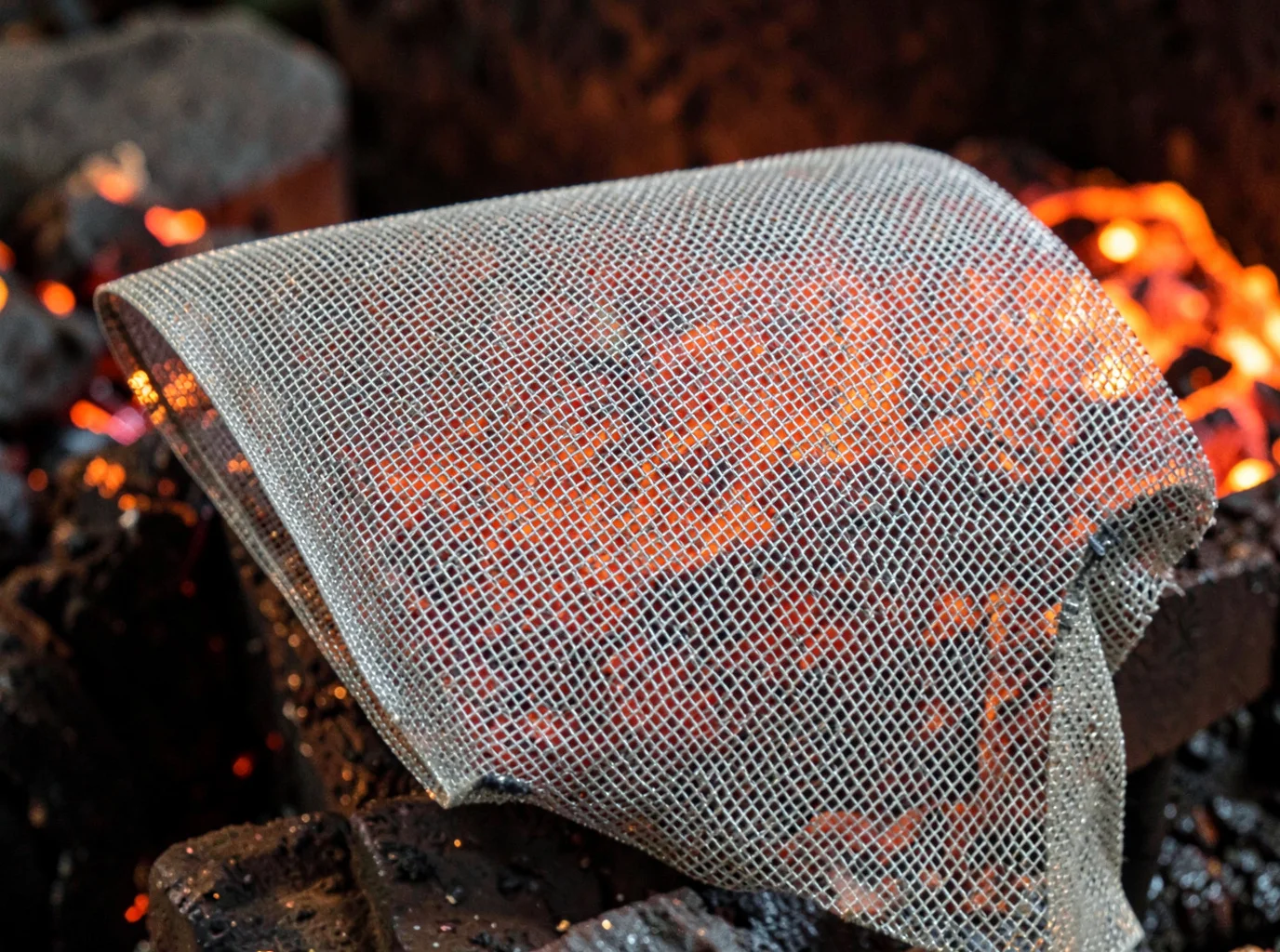
Weave pattern rarely makes the spec sheet, yet it decides whether your mesh holds its shape under flow pressure or starts sliding open mid-pour.
Plain weave interlaces warp and weft one-over-one-under. That’s the most balanced structure available. You get high resistance to yarn displacement, uniform pore geometry, and strong particle retention. It’s your default for standard filtration where dimensional stability matters more than open area.
Leno weave locks two or more warp yarns around the weft in a twisted “lock-stitch.” This resists slippage and deformation even at large, open mesh sizes. That’s exactly why it shows up as backing or support cloth in open-structure fabrics, reinforcing layers that would otherwise shift under thermal and mechanical stress.
Mock-leno is a plain-weave variant where select warp yarns skip the standard interlace at set intervals, opening up the structure. You get better airflow and thickness than plain weave, though fewer true lock points mean lower stability than genuine leno.
A documented aluminum melt filtration case pairs WA 370 (plain weave) with WA 580 (mock leno weave), selected by contaminant size and required mesh coarseness: plain for uniform base filtration, mock-leno for thicker, higher-throughput layers.
Custom Dimensions & Supply Formats: From Cut Sheets to Jumbo Rolls
Foundries don’t all pour the same way, so filters shouldn’t ship the same way either. Format choice affects your line speed, labor cost, and storage footprint just as much as mesh opening or thickness.
Three supply formats cover most production needs. Jumbo rolls work best for continuous, high-throughput automated converting, with fewer SKUs but more material tied up per roll. Slit rolls match downstream equipment width, typically 20 mm to 1,650 mm, and paper/cardboard cutting lines run 300–1,600 mm. Precision-cut sheets or discs reduce in-house cutting labor and waste, ideal for low-mix runs or complex shapes, though unit price rises if the supplier handles conversion.
930 mm is a common standard roll width, efficient for slitting into multiple lanes or roll-to-sheet conversion. Go custom width when your die layout or laminate needs tighter material utilization than a fixed parent roll allows.
Operating Temperature & Performance Limits: Selecting for Your Pouring Conditions
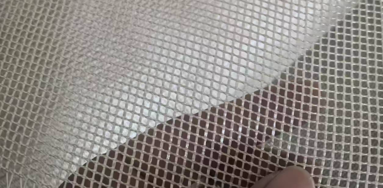
Temperature specs get treated as a single number when they’re actually a countdown timer. Standard fiberglass mesh filters run safely at 700–850°C long-term, with a softening point around 900°C. The working rule: keep your actual pour temperature at least 100°C below softening point. Push to 850°C and you’re down to a 50°C margin—workable, but only for short cycles or setups with extra heat dissipation.
High-silica fiberglass shifts the ceiling to 1450°C working temperature, softening near 1700°C. But this isn’t continuous-duty across the whole range. Duration drops fast as heat climbs:
|
Temperature Range |
Max Continuous Exposure |
|---|---|
|
1400–1450°C |
<10 minutes |
|
1450–1560°C |
<4 minutes |
|
1560–1620°C |
<15 seconds |
Selection logic: at 1400–1450°C, design your pour cycle around that 10-minute window. Above 1450°C, stop thinking in minutes—you’re now in seconds-level contact territory. Match your alloy’s pouring temperature to duration limits, not just a peak-temperature spec sheet number.
Strength & Gas Evolution Standards
Porosity isn’t just an X-ray problem. It cuts into tensile strength and elongation by shrinking the metal’s effective load-bearing cross-section and creating notch effects that propagate cracks. That’s why strength data and gas evolution numbers belong on the same supplier scorecard.
Tensile strength benchmarks for foundry qualification cluster around 550–600 MPa at room temperature. EN-GJS-600-3 requires a minimum tensile strength of 600 N/mm². Comparable cast iron and steel grades set floors between 420–600 MPa. For high-strength load-bearing parts, set the cutoff at Rm ≥600 MPa paired with gas evolution ≤30 cm³/g. General production runs can work with Rm ≥550 MPa and gas evolution ≤45 cm³/g as the acceptable ceiling.
Porosity forms when core or mold gas pressure exceeds the metal’s static pressure during solidification, trapping gas rather than letting it escape. Higher release rates mean higher porosity risk.
Fields Worth Demanding on Every Supplier Review
-
Tensile strength (Rm, N/mm²) and 0.2% yield strength (Rp0.2)
-
Elongation (A, %)
-
Gas evolution rate (cm³/g), including peak core-gas rate
-
Batch porosity rate, X-ray/CT grading, scrap rate
Ask for per-batch tensile reports alongside sample data before locking in dimensional tolerance filter specs for volume orders.
Dimensional Tolerance & Batch Consistency: What Foundries Should Verify with Suppliers
A supplier who can’t produce Cpk data on request isn’t ready for volume orders. That’s the line separating vendors who talk quality from those who prove it.
Before signing off on any dimensional tolerance filter spec, pull three documents: process capability data (Cp/Cpk, with Cpk ≥1.33 as the industry floor, ≥1.67 for safety-critical parts), an initial process study covering 30+ consecutive production units with control charts, and MSA/GR&R results confirming the measurement system itself is reliable.
For batch consistency foundry supplies, ask directly:
-
What’s the sampling ratio per batch, and is there continuous in-batch tracking on critical dimensions?
-
Can you show 12+ months of SPC/PPAP history, not just one clean batch?
-
Is lot traceability documented down to raw material furnace number?
Demand third-party reports showing consecutive-batch results, not a single sample. One-off certificates don’t prove repeatability.
Specification Matching Guide: Recommended Configurations by Application
Numbers on a spec sheet mean nothing until you match them to what’s actually coming down your runner. Here’s how the industry breaks it down by casting type.
Precision thin-wall aluminum and art castings need high-flowability media with fine particle distribution. Public reference samples show AFS 220 grain fineness paired with 32–45% flowability, gas permeability under 16–20, and compressive strength in the 1200–1380 g/cm² range. Higher-flow variants (SM/SM45 grade) exist specifically for thin-wall fill scenarios. This is your target tier when wall sections run thin and fill time is tight.
Heavy, high-flow-rate castings need a different balance: moderate fineness with stronger permeability and structural strength. The industry-standard range sits at AFS 50–60/65, with particle distribution spanning 3–5 consecutive screen sizes and total resin content at 0.8–1.5%. For large parts with extended fill times, permeability-to-strength balance matters more than raw flowability.
High-temperature steel and iron castings demand high-purity silica—SiO2 >97%—with tighter grain distribution control (3–5 screens) and low impurity/clay content kept under 0.2%. Compare that to aluminum and non-ferrous work, where SiO2 >90% is the standard purity floor.
|
Application |
Recommended Spec |
Key Metrics |
|---|---|---|
|
Precision thin-wall aluminum |
High-flow resin sand / fine grain |
40–45% flowability; AFS 220 |
|
Heavy high-flow castings |
AFS 50–60/65 quartz + low-mid resin |
3–5 screen distribution; 0.8–1.5% resin |
|
High-temp steel/iron |
High-purity silica |
SiO2 >97%; clay <0.2% |
OEM Customization Process: From Inquiry to Mass Production Approval
Skip a detail at the RFQ stage, and you’ll pay for it three weeks later during sample review. Cover this checklist upfront: product type, target volume, lead time, branding/LOGO method, packaging type, shipping destination, plus material, dimensions, weight, color, and compliance requirements.
For foundry-specific orders, add casting parameters into the RFQ: alloy type, pouring temperature, flow/fill rate, gating system layout (sprue, runner, ingate), thin-wall zones, and shrinkage/feeding requirements. These affect quotability and manufacturability—don’t leave them for a follow-up email.
Write pass/fail criteria into the RFQ itself: dimensional tolerance, surface defects, color deviation, logo placement, drop/shipping test standards.
Sample Approval Timeline
Sampling goes through sample, revision, final sample, then golden sample. Typical cycles:
|
Stage |
Duration |
|---|---|
|
First sample |
5–7 days |
|
Second revision |
3–5 days |
|
Final sample |
2–3 days |
|
Total (complex projects) |
2–3 rounds, 7–14 days |
Packaging runs parallel: stock labeling (7–10 days), custom color boxes (10–15 days), bottle recoloring (15–20 days), new tooling (25–35 days).
Log every sample’s version number, photos, revision notes, and sign-off date. Then confirm whether mass production must match the golden sample 100%—this is what prevents batch drift later.
Supplier Evaluation Checklist: Signals of Strong Customization Capability
Plenty of suppliers claim “customization.” Few actually deliver. Score each candidate against these six weighted categories before you sign a purchase order:
|
Category |
Weight |
What to Verify |
|---|---|---|
|
Customization range |
25 pts |
Mesh density, opening size, thickness, shape, custom dimensions |
|
Material/layer structure |
20 pts |
Fiber composition adjustment, interleaf media, layering options |
|
Performance evidence |
20 pts |
Micron rating, filtration efficiency, pressure drop, gas evolution data |
|
Manufacturing stability |
15 pts |
Batch consistency, MOQ, lead time, monthly capacity |
|
Engineering responsiveness |
10 pts |
Ability to modify based on drawings, samples, or performance targets |
|
Quality documentation |
10 pts |
Traceability, change-notification process, inspection reports |
Look for interleaf layering with a stated function per layer. Look for custom shapes beyond square or round, like fan-shape or trapezoidal profiles. And demand gas evolution data that repeats across three or more consecutive batches, not a single test sheet.
Conclusion
Fiberglass mesh filter customization means engineering a component that matches your alloy, your pouring temperature, and your flow requirements down to the last millimeter. Get the mesh opening size wrong, or skip verifying dimensional tolerance and batch consistency, and you pay for it later in scrap rates and rework rather than saving money on procurement.
The foundries that get this right treat filter specification as a technical conversation. They ask for sample approval before committing to volume, push suppliers on carbonized mesh filter performance data rather than just price sheets, and verify consistency batch to batch instead of only on the first order.
If you’re evaluating suppliers right now, use the checklist in this guide as your baseline. Send us your alloy type, pouring conditions, and flow targets, and we’ll recommend a configuration and get samples in your hands. That turns switching suppliers from a risk into an upgrade.