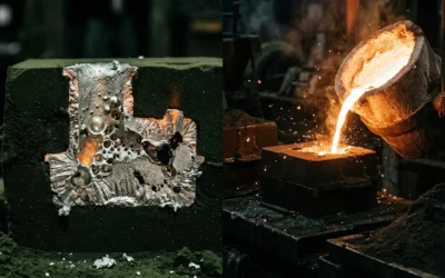
What Are Oxide Inclusions and Why They Damage Metal Quality
Oxide inclusions are non-metallic particles trapped inside your metal. They come in more varieties than most operators expect.
Common compositions include Al₂O₃, SiO₂, MnO, Cr₂O₃, and TiOₓ, plus compound forms like MnO·Al₂O₃·SiO₂ and FeO·Al₂O₃. In steel, they show up as isolated particles or complex clusters. In aluminum, the problem is different — and worse. They form bifilms: folded oxide membranes that trap air between two oxide layers. This creates a weak internal interface. No visual inspection will catch it.
How They Break Your Metal
The damage follows four patterns:
-
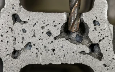
Stress concentration — inclusions break up the metal’s internal structure and create crack starting points
-
Microvoids and microcracks — small cavities form around particles and reduce the metal’s load-bearing capacity
-
Fatigue failure — fracture risk rises fast, with high-strength steel hit the hardest
-
Pitting corrosion — oxide particles act as starting points for corrosion attack
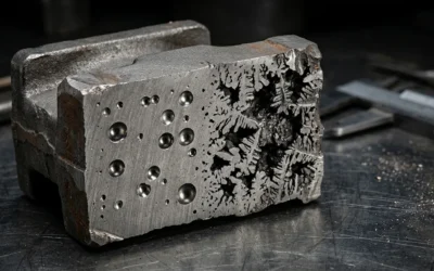
Size drives severity. Inclusions >50 µm fall into the macro-inclusion category — the most damaging type. They come from slag entrainment or secondary oxidation. For bearing steel, the critical size threshold drops to 15 µm. A few large inclusions cause far greater property loss than many small ones combined. That’s not a minor difference — it’s a significant gap.
In stainless steel welds, inclusions >1 µm are enough to trigger microcrack growth and raise pitting risk under stress. The threshold is low, and the consequences are real.
Step 1 — Assess Melt Cleanliness Before Treatment
Don’t touch the melt with a single gram of flux or a purge gas nozzle until you know what you’re dealing with. Guessing wastes time. Treating clean metal as dirty burns reagents. Treating dirty metal as clean destroys your castings.
The tools below tell you where you stand — so every downstream decision rests on data, not instinct.
For Aluminum Melts
Reduced Pressure Test (RPT) / K-mold is your fast, low-cost first pass. Pour a sample at your normal casting temperature — 680–740 °C — into a preheated K-mold (200–300 °C). Draw vacuum to 80–100 mbar for 3–5 minutes. Then calculate your Density Index:
DI = (ρ_atm – ρ_vac) / ρ_atm × 100%
Here’s the working rule: – DI < 3–5% → acceptable for most structural aluminum castings – DI 5–7% → hydrogen is elevated; strengthen rotor degassing or add flux – DI > 7% → act now — check furnace lid seals, increase refining agent dosage, extend degassing cycle
RPT won’t give you inclusion types or ppm values. It’s a directional signal, not a microscope.
RPT results look abnormal? Move to PoDFA (Porous Disc Filtration Analysis). Filter 200–400 g of melt through a 10–20 µm ceramic disc. Section and polish the disc under 50–200× optical magnification. You get quantified inclusion area fractions broken down by type: oxide films, carbides, fluorides, salt residues.
Practical benchmarks from automotive casting operations:
– Total inclusion area ≤ 0.10–0.20% → process is clean
– > 0.30–0.50% → upgrade filtration (30 ppi → 50 ppi) or add a refining step
One real-world example: a die casting facility added inline rotor degassing plus refining agent. PoDFA results showed total inclusion area drop from 0.40% → 0.12%. Oxide film area fell from 0.30% → 0.06%. That data locked in the new process parameters for good.
For continuous furnace monitoring, ultrasonic testing fills the gap. At melt temperature (680–730 °C), an immersed probe measures acoustic attenuation — α in dB/cm. Higher attenuation means more inclusions. Most facilities map their attenuation readings against PoDFA benchmarks and build three operating bands:
-
Zone A (low α) → proceed to casting
-
Zone B (mid α) → watch it closely
-
Zone C (high α) → trigger immediate refining before proceeding
For Steel Melts
Steel assessment runs on two parallel tracks: T-SLIME sampling for liquid steel at the ladle or tundish stage, and ASTM E45 rating for solidified product verification.
T-SLIME pulls a representative sample from the melt. It solidifies under controlled conditions, then runs 2D or 3D automated inclusion mapping. Pass/fail criteria for high-cleanliness grades look like this:
-
Maximum inclusion size < 30 µm
-
Average size < 10 µm
-
Count below your facility’s internal threshold per mm²
Any parameter exceeds limits? Run secondary refining or calcium treatment before casting proceeds.
ASTM E45 works on solid specimens — rolled or forged sections with a 160–500 mm² cross-section area, evaluated at 100×. It scores four inclusion types: A (sulfides), B (alumina), C (silicates), D (globular oxides). For bearing steel, the baseline control gate requires A-thin ≤ 1.0, B-thin ≤ 1.0.
The rule across both metals is the same: measure first, treat second. The assessment data from Step 1 becomes your baseline. It’s the before-and-after comparison that tells you whether your degassing, flux, and filtration steps did their job.
Step 2 — Fluxing and Slag Refining to Capture Surface Oxides
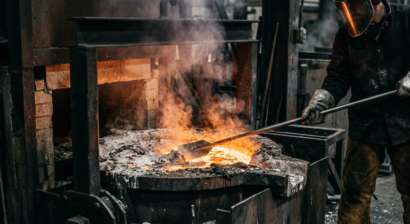
Flux does two jobs. It stops new oxides from forming. And it pulls the ones already there to the surface so you can remove them.
These are different jobs. They need different products.
Aluminum: Cover Flux vs. Cleaning Flux
Cover flux is your first layer of defense. Spread it right after charging or tapping. It forms a solid salt melt layer — NaCl–KCl based, sometimes with CaF₂ or Na₃AlF₆ added for better wetting — that blocks O₂ and H₂O from reaching the metal surface. No contact, no fresh Al₂O₃.
Dosage: 0.1–0.3% by mass. Heavy contamination or high scrap ratios? Push it to 0.5%. For Mg-bearing alloys, add more coverage and drop the temperature to 690–720 °C to hold back MgO generation.
Cleaning flux (drossing flux) works in a different way. It grabs fine oxide particles and bifilm fragments, pulls them together, and floats them up into the salt slag layer above. Same NaCl–KCl base, but loaded with NaF or CaF₂ to improve adhesion to Al₂O₃.
The sequence that works:
-
Heat to 730–750 °C
-
Add 0.1–0.2% cover flux — wait until it melts through
-
Add 0.1–0.3% cleaning flux, stir with a rotor or inert gas bubbling for 5–15 min — keep surface ripple at 1–2 cm, no splashing
-
Stop stirring. Hold 3–8 min — give inclusions time to float to the top
-
Skim the salt slag layer at a 10–20° low angle, slow and steady, working from the furnace wall inward
Stir too hard and you pull back what you just cleared out. Most operators don’t see that failure coming until it’s already happened.
Steel: Slag Chemistry and Inclusion Migration
For steel, the tool is basic slag refining. The slag doesn’t just sit on top — it dissolves oxide inclusions that rise up from the melt.
Three variables control whether this works:
-
Basicity (R ≥ 2.5): Defined as CaO/SiO₂. High basicity pushes acidic inclusions like Al₂O₃ and MnO·SiO₂ into the slag phase — the transfer reaction carries a negative ΔG°, so the chemistry is on your side. Typical ladle refining slag: 45–55% CaO, 15–20% SiO₂, 15–25% Al₂O₃, 5–10% MgO.
-
FeO control (< 1–4%): Excess FeO re-oxidizes dissolved Al and Si. That creates secondary inclusions inside the steel — exactly what you’re trying to avoid. LF/VD refining targets < 1–2% FeO. High-cleanliness grades run a two-slag approach: the first slag handles dephosphorization at higher FeO, the second drops to 1–3% FeO for inclusion absorption.
-
Argon bottom-blowing (~0.02–0.1 Nm³/min·t): Small inclusions don’t rise fast enough on their own. Argon stirring drives collision, coalescence, and upward movement. Slag viscosity matters too — hold it at 0.3–1 Pa·s so inclusions enter the slag and stay there.
Over-stir and you drag slag back into the melt. The rule is the same in steel as in aluminum: controlled agitation, not aggressive mixing.
Step 3 — Degassing and Argon Stirring to Float Inclusions
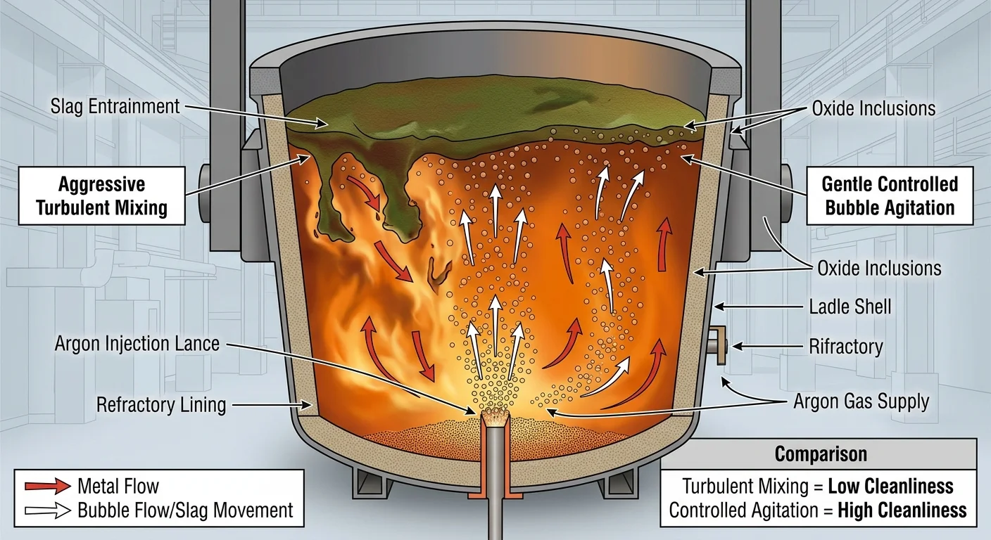
Gas does the heavy lifting here. After fluxing clears the surface, you still have inclusions suspended deep inside the melt. Fine bubbles rising through liquid metal are very effective at pulling those out.
The mechanism is simple. Bubbles attach to inclusion particles on the way up. They carry those particles to the surface and hand them off to the slag layer above. The gas movement also creates enough turbulence to drive collisions. Small particles bump into each other, merge, and grow large enough to float on their own.
Aluminum: Rotary Degassing (SNIF / RID)
Industrial data puts the numbers in perspective. After argon purging through a rotary injector, aluminum melts show:
-
Hydrogen removal: 15–40%
-
Oxygen removal: 30–50%
-
Total electrolytic inclusions reduced by ~50%, with larger particles seeing the steepest drop
Flow rate is the key control variable. Most operators get this wrong. Numerical simulations show a clear split:
-
25 L/min — gas flow deflects toward the furnace wall and creates dead zones where inclusions stagnate
-
50 L/min — inclusions move toward the metal surface and into the slag layer with much better consistency
Steel: Ladle Bottom-Blowing Argon
Soft stirring beats aggressive stirring — by a wide margin. Vacuum degassing followed by soft stirring cuts total inclusions >10 µm by an average of 65%. Switch to hard stirring, and those same inclusions jump by 400%.
The reason is straightforward. Strong agitation pulls particles back up that already floated to the surface. You undo all the progress.
Three failure modes to avoid:
-
Open eye on the ladle surface — exposes steel to atmospheric reoxidation
-
Slag entrainment — drags refining slag back into the melt
-
Re-suspension — breaks up coalesced clusters into fine particles that are harder to remove later
A 1,000 lb ladle trial with plug-based bottom-blowing proved this point. Bottom argon injection without careful flow control reduced cleanliness. It disrupted the protective slag layer and introduced elevated TiO₂ and MnS inclusions.
The safe flow window that avoids these failure modes: < 0.15 m³/min (5 scfm). Stay in that range, and bubbles stay gentle enough to lift inclusions upward without tearing the slag layer apart.
The underlying rule: more gas is not more clean. Use enough movement to promote collision and flotation — then back off and let inclusions rise.
Step 4 — Sedimentation and Holding Time Optimization
Physics does the work here — but only if you give it enough time.
After degassing and argon stirring, your melt still isn’t clean. Inclusions remain suspended through the bulk. What clears them next is a density gap. Aluminum melt at 700 °C sits at 2.3–2.4 g/cm³. Al₂O₃ inclusions run 3.6–4.0 g/cm³. That gap drives separation — heavier oxide clusters sink, lighter slag phases rise.
Aluminum: How Long to Hold and at What Temperature
The Stokes equation gives you the numbers:
-
20 µm inclusions float or settle at 0.04–0.4 mm/s
-
50 µm inclusions move 6× faster — hitting 0.2–2 mm/s
For a typical holding depth of 0.3–0.5 m, full separation takes 5–30 minutes in theory. Real operations apply a 3–5× safety buffer. That pushes actual holding times to 15–120 minutes.
The sweet spot most aluminum operations land on: 20–30 minutes at 600–630 °C.
Here’s the removal data at 600–620 °C:
|
Hold Time |
10–30 µm inclusions |
>30 µm inclusions |
|---|---|---|
|
10 min |
40–50% removed |
— |
|
20 min |
60–70% removed |
— |
|
30 min |
~80–85% removed |
~90% removed |
|
>60 min |
Marginal gains (<5–10%) |
Diminishing returns |
Past 60 minutes, the removal curve flattens out. You’re burning metal and losing cycle time for almost no cleanliness gain.
Keep surface velocity at <0.05 m/s — target 0.01–0.03 m/s for best results. Design your holding vessel with an L:W ratio of 4–6:1. This promotes laminar, layered flow. Set depth at 0.3–0.8 m. One detail that often gets missed: only 60–80% of your nominal residence time is actually working. Inlet turbulence and outlet recirculation consume the rest.
Steel: Tundish Design and Residence Time Targets
Steel is harder to clean through sedimentation. At 1550–1600 °C, steel viscosity runs 6–7 mPa·s — far higher than aluminum. Even with a larger density gap (Δρ ≈ 3.0–3.4 g/cm³ for Al₂O₃ vs. steel), a 30–50 µm inclusion still needs 2–6 hours to float across a full tundish depth of 0.7–1.0 m on its own. That’s not practical for continuous casting.
So tundish geometry carries the load instead:
-
Standard continuous casting: target residence time τ ≈ 6–10 minutes
-
Low-inclusion quality grades: push to τ ≈ 10–20 minutes
-
Bearing steel and ultra-clean grades: design for >20–30 minutes, using dual dam-and-weir layouts
Dam-and-weir layouts push steel through an S-shaped or Z-shaped path. CFD and water model studies back this up with clear numbers: inclusions >70 µm see flotation removal climb from 40–50% up to 70–80%+. At the same time, short-circuit flow drops from >30% down to <10–15%.
Keep surface velocity capped at <0.15 m/s. Go past that limit, and you pull slag back into the melt — erasing everything the refining sequence just accomplished.
Step 5 — Ceramic Foam Filtration as the Last Physical Barrier
Everything upstream — the fluxing, the degassing, the 30-minute hold — reduces your inclusion load. It doesn’t eliminate it. Fine particles still enter the mold. None of the previous steps caught them. ceramic foam filtration stops those particles.
A ceramic foam filter (CFF) is a three-dimensional pore network. Metal passes through at 10 mm/s. Inclusions don’t make it. The filter catches them through three overlapping mechanisms: physical blocking at the pore openings, deep-bed interception inside the structure, and adsorption onto ceramic surfaces. At the start of a cast, open pores do the screening. A deposit layer builds on the inlet face over time. The filter then shifts into deep-bed mode — finer capture, higher pressure drop, shorter remaining life.
Aluminum: Choosing the Right PPI
PPI selection is a cleanliness-versus-flow tradeoff. Too coarse and fine oxides slip through. Too fine and you’re fighting pressure drop and clogging for the entire cast.
|
PPI |
Effective Cut-Off |
Typical Application |
|---|---|---|
|
10 |
>200–300 µm |
Large ingots, low-Mg alloys |
|
20 |
>100–150 µm |
DC ingot, rolling slab |
|
30 |
>50–80 µm |
Aerospace plate, foil stock |
|
40–50 |
20–50 µm |
Small, high-cleanliness castings |
Filter thickness runs 50–75 mm on standard plates. Metal velocity through the CFF needs to stay between 5–15 mm/s. Drop below that range and priming becomes unreliable. Go above it and pressure drop spikes — clogging speeds up fast.
Installation matters as much as specification. Place the filter box just upstream of the casting mold. Keep it submerged and sealed with ceramic fiber gaskets. Zero bypass leakage. Pre-heat the launders and box before metal arrives. Let the initial metal front wet and heat the filter at a slow, controlled pace. Thermal shock cracks filters. Cracked filters let inclusions pass straight through.
Clogging signals to watch:
– Metal level rising above the filter at constant casting rate
– Irregular meniscus or unstable flow into the mold
– Heavy deposition visible on the inlet face after casting
One filter per heat is standard practice for DC ingots and slabs. Throughput capacity runs 20–60 tons per filter, depending on PPI and incoming melt cleanliness.
Steel: Tundish Filters and Long Nozzle Design
In continuous casting, the tundish CFF or porous plug sits at the outlet region, just before the submerged entry nozzle (SEN). It targets Al₂O₃, calcium aluminate, and spinel inclusions in the 20–200 µm range.
The SEN handles a separate job. It keeps steel submerged from tundish to mold. This cuts off air aspiration and re-oxidation at the most exposed transfer point.
Clogging recognition in steel systems is indirect:
– Tundish level rising at constant casting speed
– Stopper rod opening increasing to maintain flow rate
– Mold level fluctuations without change in set parameters
Tundish outlet filters run one per sequence — 100–200 ladle tons before replacement. Clogging indicators show up earlier sometimes. Don’t push it. A clogged nozzle breakout costs far more than an unplanned filter change.
Replacing filters in either system? Keep argon shrouding active over exposed metal surfaces. Splashing during filter changeover triggers secondary oxidation. That undoes everything the refining sequence built.
Step 6 — Advanced Methods: Electromagnetic Separation and Vacuum Treatment
Filters and flux handle the bulk of it. But some inclusions — the ones below 50 µm — slip through every physical barrier you’ve already set up. That’s where electromagnetic separation and vacuum treatment come in.
Electromagnetic Separation for Aluminum: Targeting What Filters Miss
Run an alternating magnetic field through molten aluminum and something unexpected happens. It doesn’t grab the inclusions. It moves the metal around them. The induced eddy currents generate Lorentz forces. Those forces create shear flows and secondary circulation patterns. Non-conductive oxide particles — Al₂O₃, nitrides, carbides — get pushed toward low-turbulence zones near the channel walls or the free surface. From there, you can remove them.
The frequency you pick determines which particle sizes you target:
-
50 Hz to a few hundred Hz — effective against inclusions >20–30 µm
-
1–5 kHz — stronger eddy current shear, needed for particles <20 µm
Key operating parameters for industrial-scale electromagnetic filter channels:
-
Magnetic flux density: 0.05–0.3 T near the channel lining
-
Coil current: 2–10 kA (rms), 10–40 turns, power draw 100–500 kW
-
Channel dimensions: length 1–3 m, cross-section 100×100 mm to 300×300 mm, liquid depth 50–150 mm
-
Metal flow velocity: 0.05–0.3 m/s
-
Residence time: 20–120 seconds — long enough for fine inclusions to complete one or two lateral drift-and-accumulation cycles
-
Operating temperature: 680–760 °C, with Al₂O₃ or high-alumina refractory lining
Removal efficiency data, for particles <50 µm:
|
Inclusion Size |
Conditions |
Removal Rate |
|---|---|---|
|
>30 µm |
0.1–0.2 T, 50–60 Hz |
70–90% |
|
10–20 µm |
Combined with inline filtration |
40–60% |
|
5–15 µm |
High-frequency 1–3 kHz system |
Count reduced 30–50%; >15 µm reduced 60–80% |
In high-frequency experimental systems, the residual inclusion area fraction drops from 0.02–0.03% down to 0.005–0.01%. For 6xxx/7xxx alloy extrusion billet, pair electromagnetic separation with ceramic foam filtration and you cut inclusion-related fatigue fracture rates by 50–70% in the early failure stage.
The cost isn’t small — $300,000 to $1.5 million USD per line, depending on power, water-cooled coil complexity, and automation. European and Japanese aluminum producers running >100,000 t/year often recover that cost within 1–3 years. They do it through scrap rate reductions of 20–50% and yield improvements of 1–3 percentage points on high-end sheet and extrusion products.
Vacuum Treatment for Steel: VD, VOD, and RH
Steel’s advanced inclusion removal works on a different principle. Drop the pressure low enough and dissolved gases escape. As they rise, they pull inclusions with them.
Rising CO, H₂, and N₂ bubbles give fine oxide particles something to stick to. Inclusions cluster onto those bubbles as they ascend. They merge into larger composite particles — after RH treatment, average inclusion size shifts from 3–5 µm up to 10–20 µm. Larger particles float faster. That’s the whole mechanism.
What each system delivers:
-
VD (Vacuum Degassing): Working pressure 0.67–2.7 kPa, with deep degassing processes reaching 0.13–0.4 kPa. Dissolved oxygen drops from 40–80 ppm down to 5–20 ppm. Nitrogen falls from 60–80 ppm to 20–40 ppm. Hydrogen drops from 3–5 ppm to 1–2 ppm. Cycle time: 30–60 min/heat. Investment: $8–20 million USD for a 100–200 t furnace.
-
VOD (Vacuum Oxygen Decarburization): Adds an oxygen lance to VD. Use it for high-Cr stainless and ultra-low-carbon grades — carbon can drop from 0.03–0.05% down to 0.003–0.005%. Equipment and refractory costs run about 20–40% higher than standard VD.
-
RH (Recirculating Vacuum Degassing): Circulation flow rates of 20–60 t/min on 100–300 t furnaces. Total treatment time: 15–30 minutes. Investment lands at $15–35 million USD per unit. RH-OB variants add oxygen injection alongside secondary slag practice — so inclusion modification and degassing happen in a single step.
Operating costs run $3–10 USD per ton of steel. High-end stainless and automotive sheet grades sit at the upper end of that range.
Documented outcomes across vacuum-treated heats:
– Continuous casting breakout rates down 30–70%
– Low-temperature impact toughness and fatigue life up 10–30%
– Hydrogen-induced cracking and gas-related scrap rates down >50%
The tradeoff is clear. Electromagnetic separation and vacuum treatment both cost serious capital. Neither is justified for commodity grades. But for bearing steel, aerospace aluminum, or any application where a single inclusion-related failure costs more than the equipment itself — these methods aren’t advanced options. They’re the baseline.
Step 7 — Low-Turbulence Casting Practice to Prevent Reoxidation
Every step before this one cleaned your metal. Step 7 is about not ruining it.
Turbulence during casting forms fresh oxides fast. Surface films fold inward. Bifilms and reoxidation inclusions get pulled into metal that was clean just seconds ago. All the degassing, fluxing, and filtration you ran upstream gets undone — right at the pour.
The fix isn’t complicated. It’s disciplined.
Control the Flow, Not Just the Chemistry
Lower your pouring height. Free-fall impact breaks the liquid surface and folds oxide film straight into the melt. Keep the metal stream short and continuous.
Increase and smooth your runner cross-sections. Sharp bends, sudden contractions, and step transitions create local high-velocity jets. Those jets pull in air. Widen the path and round every corner.
Use bottom-gated or tilt-pour filling. Metal should rise along the mold wall — steady, controlled, climbing. Not dropping, splashing, or churning. The target is smooth flow, not tumble.
For steel continuous casting, the protective shrouding chain must stay complete from ladle to mold: long nozzle → sealed connections → tundish covering flux. Any gap in that chain exposes the steel stream to air. Secondary oxidation starts again — fast.
Dry Everything Before Metal Arrives
Moisture in molds, cores, or launder systems turns to vapor on contact with liquid metal. That vapor creates local turbulence, hydrogen porosity, and combined oxide-gas defects — all in one event.
Pre-heat molds, runners, and ladles fully. Check for condensation after cooling. Reassemble before humidity gets back in.
The working principle is the same for aluminum and steel: dry + low drop height + smooth fill = no reoxidation. Treat these as one control system, not three separate checklist items.
Oxide Inclusion Removal: Aluminum vs. Steel Side-by-Side Comparison
Same problem. Completely different solutions. That’s the short version of how aluminum and steel handle oxide inclusions.
The longer version covers oxide types, temperature windows, and process logic. These two metals take very different paths.
What You’re Fighting Is Different
In steel, the main threat is Al₂O₃ — sharp-edged, cluster-prone, and formed the moment you add aluminum as a deoxidizer. You can’t stop it from forming. So the strategy focuses on modifying and removing it after the fact. Calcium treatment reshapes rigid Al₂O₃ clusters into spherical, low-melting-point CaO–Al₂O₃ globules. Those float out. The ones that don’t get absorbed by a high-basicity slag.
In aluminum, the enemy is the oxide film — thin, folded sheets of Al₂O₃ and MgO·Al₂O₃ spinel. These films often run 0.1 to several mm long. They don’t cluster. They drape. Their density sits close to the melt, so they don’t rise to the surface on their own. The strategy here is prevention first, then physical removal.
Steel’s core logic: generate → modify → float.
Aluminum’s core logic: prevent → agitate → filter.
Temperature Windows Tell the Story
|
Parameter |
Aluminum |
Steel |
|---|---|---|
|
Refining temperature |
690–740 °C |
1,580–1,630 °C (LF) |
|
Casting temperature |
650–730 °C |
1,530–1,580 °C (tundish) |
|
Primary removal method |
Rotary degassing + CFF |
Argon stirring + slag + Ca treatment |
The temperature gap is massive. Aluminum refines at under 750 °C. Steel runs at over twice that. This gap shapes everything — the equipment, the chemistry, and the cost.
Cost Gap Is Real
A mid-scale aluminum line with rotary degassing and ceramic foam filtration costs $30,000–$100,000 in capital. Operating costs land at $5–15/ton.
A steel ladle furnace alone runs $10–30 million. Add RH vacuum degassing and you’re looking at $20–50 million per unit. Running costs hit $7–18/ton before calcium wire.
That cost gap reflects the temperature, the chemistry, and the consequences of getting it wrong. Higher stakes demand heavier investment — and steel leaves very little room for error.
Prevention Best Practices: Stop Inclusions Before They Form
The cheapest inclusion to remove is the one that never enters your melt.
Every removal step in this guide costs time, reagents, and equipment wear. Prevention costs almost nothing by comparison. It just requires discipline at the front end of your process.
Start with your raw materials. Clean scrap is not a preference. It’s a cleanliness variable with real, measurable consequences. One alloy wheel plant proved this: clean scrap ratios climbed from 60% to 90%. Ceramic-type inclusion defect rates dropped from 1.2 defects/ton to 0.3 defects/ton. Scrap rates fell from 2.5% to 0.6%. That’s one input change producing a fourfold defect reduction.
The incoming material standard that drives this result:
– Surface oil contamination ≤ 0.1 wt%
– Non-metallic surface coverage < 3–5%
– Every 1% reduction in non-metallic surface coverage cuts large inclusions (>100 µm) by 8–12%
Refractory condition matters just as much. Worn linings shed particles into your melt. Erosion depth at 60–70% of design thickness means it’s time to stop and repair. Facilities that hold to this threshold bring abnormal inclusion events down to 20–30% of their previous frequency.
Preheat everything — and do it the right way. Skip the low-temperature hold stage during aluminum furnace warm-up, and refractory spalling more than doubles. That pushes inclusion counts per mm² up by 50–80% in the first melt cycle alone.
Conclusion
Oxide inclusions don’t announce themselves. They hide inside your melt, waiting to ruin every pour, every casting, every finished part.
But now you have the full playbook. Check cleanliness first. Flux hard and with intent. Stir with purpose. Filter before casting. Cast with discipline. No matter if you’re working molten aluminum or steel, the rule stays the same: attack inclusions at every stage, not just one.
The cleanest metal doesn’t come from luck. The top foundries run all seven steps without cutting corners. They treat inclusion control as a full system — not a one-time fix.
So here’s your next move: audit your current process against this framework. Find the step you’re skipping or doing poorly. That gap is where your scrap rate comes from.
Clean metal starts with a clear, intentional process. You now know how to remove oxide inclusions from molten aluminum and steel. Go build a melt practice that does justice to the alloys you’re working with.