
Every casting defect tells the same frustrating story — scrapped parts, rework costs, and a production line that never delivers the quality your customers demand. The root cause? Contaminated metal flow. The fix is simpler than most foundry engineers expect.
Ceramic filters have become one of the most reliable solutions against the top 8 Casting defects that drain profitability across industries. That includes non-metallic inclusions, porosity, pressure leakage, and punishing scrap rates.
This guide breaks down how Ceramic filtration solves each problem at the source. You’ll also find out what to look for when picking the right filter for your specific application.
Eight defects. One filtering solution that cuts scrap, rework, and mechanical scatter across all of them.
Here’s how ceramic filters address each problem — with real numbers:
|
# |
Casting Defect |
Primary Mechanism |
Key Benchmark |
|---|---|---|---|
|
1 |
Non-metallic inclusions |
Sieving + deep bed filtration |
Scrap reduced from >3–5% → <1–2% |
|
2 |
Reoxidation / oxide films |
Promotes laminar flow |
Defect frequency down 30–60% |
|
3 |
Slag & dross |
Direct interception in gating |
Filter sized at 2–3× expected inclusion mass |
|
4 |
Cold shuts & misruns |
Stabilizes metal front velocity |
Runner cross-section reduced 10–30% |
|
5 |
Gas porosity |
Reduces air entrainment |
Porosity frequency down 25–50% in aluminum |
|
6 |
Macro shrinkage |
Keeps feeding paths open |
1–3 point yield improvement with riser redesign |
|
7 |
Surface scabs & roughness |
Captures shell/sand fragments |
Rework reduced 30–70% in investment casting |
|
8 |
Mechanical property scatter |
Fewer bifilms and crack initiators |
Fatigue life up 20–50%; tensile scatter down 10–30% |
Each section below covers how the mechanics work, what results you can expect, and which filter options make the biggest impact.
What Makes Ceramic Filters Effective at Eliminating Casting Defects
A ceramic filter handles several jobs at once. That’s why no single alternative produces the same result.
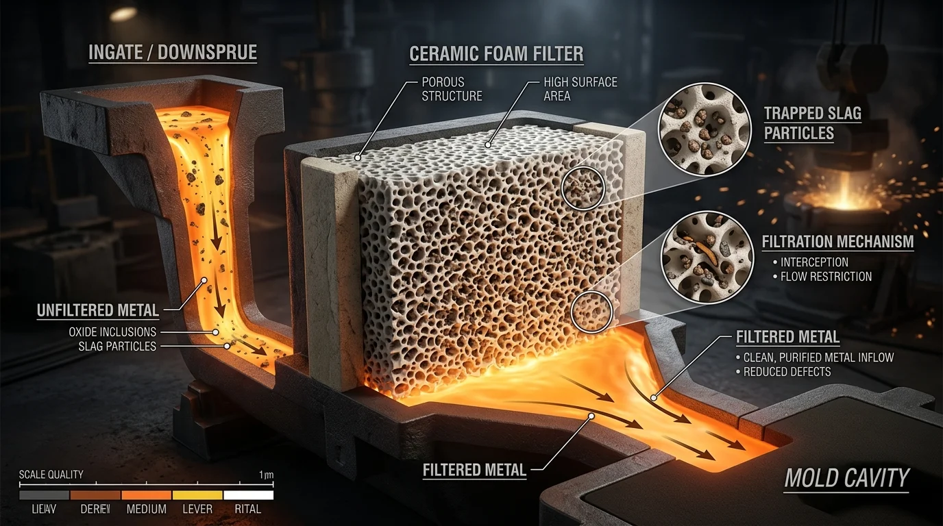
Molten metal can’t travel in a straight line through a ceramic foam filter‘s 3D pore network. Every pore forces a direction change. Every wall creates a collision point. That repeated contact between metal and ceramic surface traps inclusions — not just the large ones, but fine oxide films and reoxidation products that pass straight through less refined methods.
Four distinct layers work together inside the filter:
-
Screening — Coarse pores catch large slag pieces and sand lumps before they reach the cavity
-
Deep-bed filtration — Smaller internal throats trap fine non-metallic inclusions deeper inside the filter body
-
Flow rectification — The porous structure breaks up turbulent jets and converts chaotic metal movement into near-laminar flow, cutting air entrainment and bifilm formation at the source
-
Residence time — Metal slows inside the filter long enough for buoyancy to push some inclusions back upstream, reducing the total inclusion load entering the mold
Flow rectification is worth a closer look. Gas porosity, oxide films, and mechanical property scatter all trace back to turbulence. A ceramic filter doesn’t just clean the metal — it changes how the metal behaves before it fills the cavity.
Material Chemistry Determines Whether Filtration Helps or Hurts
Filter selection isn’t just about pore size. Use the wrong ceramic chemistry and the filter itself becomes a defect source.
|
Filter Material |
Target Alloy |
Why It Matters |
|---|---|---|
|
Alumina (Al₂O₃) |
Aluminum & low-temp non-ferrous |
Resists molten Al attack up to ~1,000–1,100°C without dissolving |
|
Silicon carbide (SiC) |
Cast iron, bronze, brass |
Higher thermal shock resistance prevents filter cracking at iron pouring temps |
|
Zirconia (ZrO₂) |
Steel & high-temp superalloys |
Handles 1,550–1,700°C without erosion; critical where ceramic chips in steel are catastrophic |
|
Magnesia (MgO) |
Magnesium alloys |
Chemical compatibility with reactive Mg prevents secondary reactions |
A zirconia filter eroding in an aluminum melt injects ceramic particles into the casting. So does an alumina filter cracking during steel pouring. Matching chemistry to application is not optional.
PPI Rating Controls the Inclusion-Flow Tradeoff
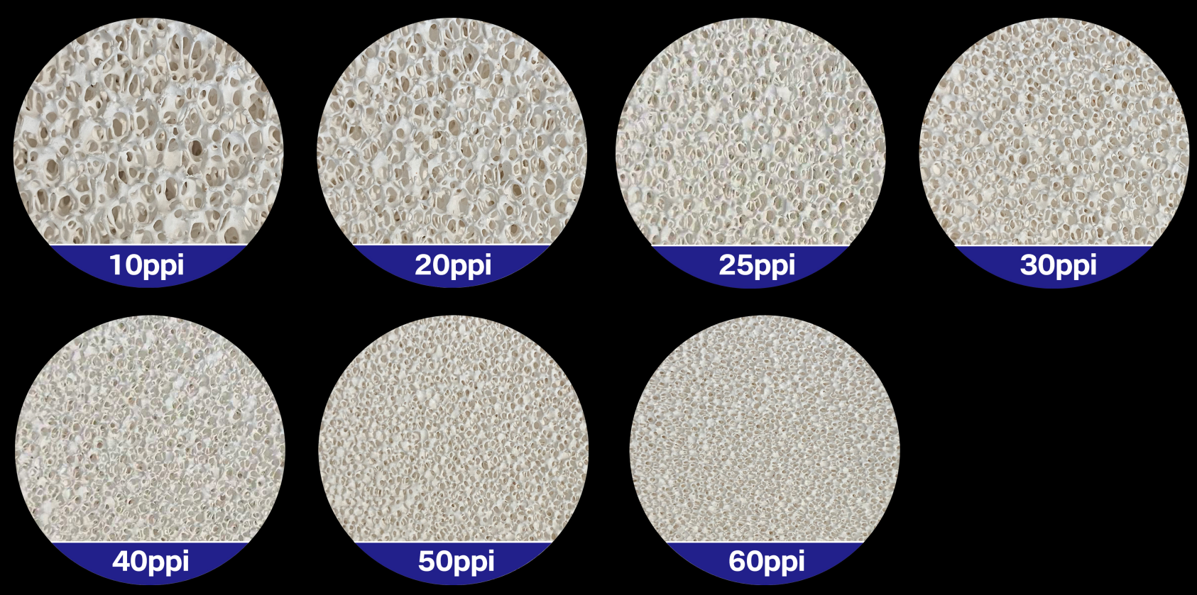
PPI — pores per inch — is the main dial between filtration fineness and flow resistance:
-
10–20 PPI: High-flow option for large iron and steel castings. Catches coarse slag and sand, but finer inclusions pass through. Best choice when misruns are the bigger risk.
-
20–30 PPI: The general-purpose range for most non-ferrous and iron castings. Good oxide and sand inclusion reduction without excessive pressure drop.
-
40–50 PPI: For aerospace-grade aluminum or critical structural parts where micro-inclusions and bifilms control fatigue life. You get superior fine oxide capture — but gating must be redesigned to handle the higher pressure drop, or misruns follow.
Size the filter area at 2–4× the choke area of the gating system. Too small and metal velocity through the filter rises, risking erosion and turbulent re-entrainment. A larger area means lower velocity, more laminar flow, and better capture — this matters most at higher PPI ratings.
Where You Place the Filter Changes What It Can Accomplish
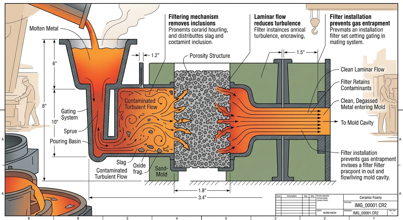
Location is the variable most engineers underestimate. Place the filter downstream of major turbulence sources — after sprues and sharp runner turns — and as close to the mold cavity as practical. Filtration upstream of a turbulent gating section re-contaminates the metal before it fills. You lose most of the benefit.
Pair filter placement with non-pressurized gating to keep metal velocity low throughout. A ceramic filter can’t undo oxide films and air entrapment that form inside the cavity after filtration. Correct placement combined with solid gating design locks in the cleanliness the filter creates.
Conventional Foam vs. Engineered 3D-Printed Filters
Here’s a performance gap that doesn’t get enough attention: conventional Ceramic foam Filters can allow up to 40% of inclusions to pass through, depending on design. That’s not a rare failure — that’s the documented ceiling for some standard foam products.
Engineered 3D-printed ceramic filters close that gap by a wide margin. Their internal geometry is controlled by design, not left to chance during foam manufacturing. You get:
-
Consistent, repeatable flow rates from filter to filter — this removes the mold-fill variability that scatters defects across multi-cavity tools
-
Non-porous structural walls that don’t shed ceramic fragments — so you avoid the secondary inclusion risk that undermines some foam filters
-
Tuned stagnation zones and sharp turns that trap inclusions without the random geometry that lets inclusions find low-resistance paths through conventional foam
In one documented case, a 15 kg steel casting switched to filtered gating. Weld repair was eliminated. Inclusions and surface defects dropped to the point where post-cast remediation was no longer needed. That’s what correctly specified ceramic filtration can deliver.
Defect #1: Non-Metallic Inclusions (Slag, Sand, Oxide Films)
Non-metallic inclusions are the most common casting defect — and the most damaging. Slag stringers, sand grains, and oxide films hide inside a finished part. You won’t see them until machining exposes the surface, or worse, until the part fails in service.
Three sources cause most cases:
-
Slag carry-over from ladle to mold brings in CaO–SiO₂–Al₂O₃–MgO particles ranging from 0.5 to 10 mm. No filtration or slag-stopping measures? Entrainment reaches 0.5–2.0 kg per ton of steel.
-
Reoxidation during pouring turns dissolved Al, Si, and Ca into solid Al₂O₃ and calcium-aluminate particles. These form irregular clusters from 1 µm up to several hundred µm. They build up near turbulent zones and top surfaces.
-
Sand erosion pulls silica grains off mold walls and gating surfaces. It leaves patch defects several millimeters thick in areas where metal velocity peaked.
How Ceramic Filters Intercept Each Source
Ceramic foam filters work through three overlapping methods:
-
Sieving catches particles above 30–50 µm.
-
Inertial impaction pushes smaller particles into pore walls as the metal changes direction.
-
Adsorptive capture holds oxide films against ceramic ligament surfaces through chemical affinity and surface roughness — even thin, wrinkled skins that would pass through coarser traps.
Flow velocity through the filter matters as much as pore geometry. Keep metal velocity at 0.3–0.5 m/s and capture efficiency rises fast. Go above that range and turbulence pulls back what the filter already caught.
The results are well-documented. Foseco case data from Ductile Iron foundries show non-metallic inclusion-related scrap falling 50–75% after combining Ceramic foam filters with improved gating. In steel, full inclusion control — calm ladle practice, tundish flow management, and filtration — cuts inclusions ≥20–30 µm by 80–95% between ladle and final product.
Those numbers carry real mechanical weight. Non-metallic inclusions are the top identified cause of fatigue failure in crankshafts, gears, and roller shafts. In bearing steels, reducing oxide inclusion content to total oxygen ≤25–30 ppm extends rolling contact fatigue life by 30×. Exogenous inclusions — the large slag and sand types — do the most damage. Their stiffness and thermal expansion differ from the surrounding metal matrix. That mismatch concentrates stress at the particle boundary, turning each inclusion into a reliable crack starting point under repeated load.
The filter doesn’t just clean the metal. It takes away the conditions that lead to early failure.
Defect #2: Porosity (Gas Porosity & Shrinkage Porosity)
Porosity comes in two forms — and they’re not the same problem.
Gas porosity shows up as smooth, rounded voids. Hydrogen bubbles in aluminum. Blowholes near cores. Pinholes spread across the entire cross-section. You won’t see them until a machinist cuts through the surface. A pressure test can also expose the leak path that was hiding inside.
Shrinkage porosity looks different under the microscope. It’s irregular, interdendritic, and concentrated in the last zones to solidify. The cause is a feeding failure — not a gas problem. Thick sections, hot spots, and undersized risers all create the right conditions. No amount of filtration fixes a shrinkage void. That void formed because the metal ran out before the part finished contracting.
That distinction is critical. Ceramic filters target gas porosity. Shrinkage porosity is a different fight entirely.
How Ceramic Filters Break the Gas Porosity Chain
Gas porosity doesn’t start with gas alone. It starts with oxide films and non-metallic inclusions — and those are what ceramic filters remove.
Here’s the mechanism: turbulent metal flow generates oxide films and bifilms. Those films become preferred nucleation sites for dissolved hydrogen during solidification. More inclusions mean more bubble nucleation points and more coalescence. The end result is a connected porosity network that kills pressure integrity and fatigue life.
Ceramic filters cut that chain at two points:
-
Inclusion capture — Oxide films, slag, and sand fragments get trapped inside the filter body before they reach the mold cavity. Fewer inclusions means fewer nucleation sites for gas bubbles.
-
Flow calming — The pressure drop across the filter reduces metal velocity and Reynolds number. Turbulent jets become near-laminar flow. Less turbulence means fewer new oxide films form during filling.
The combined result: lower bubble number density, smaller isolated pores, and a measurable drop in total gas porosity fraction.
What the Numbers Show
In aluminum castings, the benchmark hydrogen threshold for minimizing visible gas porosity is ≤0.15–0.20 mL/100 g Al. Uncontrolled melts run at 0.25–0.30 mL/100 g. Combine ceramic filtration with rotary or vacuum degassing and the radiographic gas porosity area fraction drops 30–70% against unfiltered, undegassed baselines. Yield strength and fatigue life follow — expect a 10–20% improvement once gas and inclusion porosity come under control.
In ductile and grey iron, the picture is similar. Inclusions in unfiltered iron act as nuclei for both gas bubbles and microshrinkage clusters. Foundry plant data shows overall porosity-related scrap rates dropping from 8–10% down to below 3–4% after combining ceramic filtration with optimized inoculation and clean melt practice.
Shrinkage Porosity: Where Filters Step Back
Ceramic filters play a limited role here. More laminar filling does improve feeding uniformity at the margins. But shrinkage porosity is governed by riser design, section modulus, and solidification pattern — not inclusion content. Thermal simulation tools like the Niyama criterion identify the hot spots. Internal chills relocate last-to-freeze zones. Riser geometry determines whether liquid metal can reach those zones in time.
The priority for porosity control is clear: install the filter to handle gas and inclusion-driven porosity; redesign the feeding system to handle shrinkage. Treating both as the same problem with the same fix is where remediation plans fall apart.
Filter Specification for Porosity Control
Keep metal velocity through the filter below 0.5–0.7 m/s to maintain laminar conditions. For aluminum sand castings, 10–30 PPI covers most applications. Parts with higher cleanliness demands — aerospace structural components, pressure-tight housings — need finer pore ratings. Plan for gating redesign to compensate for the added pressure drop.
Pair filtration with low-gas-evolution core materials, proper venting near core assemblies, and preheated, dry tooling. Core gas blowholes — large, smooth cavities that form next to cores as organic binders degrade — won’t be stopped by filtration alone. Venting gives trapped gas an escape route. Filtration removes the inclusions that would have anchored those bubbles in place.
Defect #3: Turbulence-Induced Cold Shuts and Misruns
Two metal streams meet inside the mold. Both carry oxide skins on their surfaces. They touch — and don’t fuse. That’s a cold shut: a crack-like gap that cuts through part or all of the cross-section. You won’t see it until machining exposes it — or the part fails.
This defect doesn’t start at the meeting point. It starts upstream, in the turbulence.
How Turbulence Creates the Conditions for Cold Shuts and Misruns
Chaotic metal flow does two destructive things at once. It folds oxide films into the stream — building up bifilms that coat the advancing metal front. It also breaks the flow into jets and sprays, which sharply increases surface area and speeds up heat loss.
That fragmented, already-cooling metal then hits a thin section. From there, one of two things happens:
-
Cold shut — two oxide-covered fronts meet at too low a temperature to fuse, leaving a lap line or discontinuity through the part
-
Misrun — the metal front drops below liquidus before reaching the far end, freezing short of a full fill
The triggers are predictable. Sharp cross-section changes spike local Reynolds numbers. High sprue fall heights generate waterfall-effect splash at the base. Runner corners with poor transitions break the surface front into semi-solid slugs before they ever reach thin walls.
The margins are tight. In aluminum sand castings, fill velocities below 0.3–0.4 m/s at thin gates — combined with high mold heat extraction — push the front toward early freezing. Steel and cast iron poured at 30–50 °C below the recommended temperature show a clear rise in both defect types. In zinc die casting, cold flow defects track closely with flow-length-to-thickness ratios above 80–100:1.
What Ceramic Filters Fix Here
Ceramic Foam Filters tackle this problem as flow regulators — not just inclusion traps.
Pushing molten metal through a 10–30 PPI cell structure breaks large eddies and turns turbulent inflow into smooth, plug-like flow downstream. Velocity spikes at ingates drop. Air entrainment drops. The metal front reaches the mold cavity as a coherent, continuous stream — exactly what you need to prevent oxide-lap cold shuts and thin-section misruns.
The back-pressure effect adds another layer of control. A well-sized filter in aluminum Sand casting produces 2–10 kPa of pressure drop across 20–50 mm of filter thickness. That back-pressure cuts upstream flow fluctuations and smooths the advancing front.
Sprue-Base vs. In-Runner Placement
Filter placement determines how much of the system gets the benefit of flow straightening.
Sprue-base filters turn free-fall sprue flow into distributed, near-laminar flow before it enters the runners. The entire downstream Gating System benefits. This is the go-to setup for aluminum and iron sand castings where thin extremities are the main misrun risk — as long as filter face area is sized to keep metal velocity at or below 0.4–0.6 m/s. Size the filter too small and fill time goes up by 10–20%, which can itself trigger misruns in borderline thin sections.
In-runner filters target a specific cavity or branch. Total pressure drop stays lower, and global fill time stays in range. That’s useful when cycle time is tight or only one region shows cold shut problems. The tradeoff: upstream turbulence stays unaddressed. Oxide and gas from the sprue travel downstream and build up against the filter face.
For multi-cavity die and permanent mold tools, in-runner filters are often the practical choice. The target is to keep cavity fill within 0.05–0.4 seconds for zinc and aluminum Die casting — fast enough to prevent cold flow, controlled enough to support laminar fronts.
Sizing and Process Parameters That Seal the Fix
Picking a filter without aligning the rest of the process leaves results on the table. Three variables control the outcome:
-
Filter face area — Calculate volumetric flow rate from your target fill time, then set the area so velocity through the filter stays below the laminar threshold. For aluminum, 10–20 PPI covers most sand casting applications.
-
Pouring temperature — Stay toward the higher end of the recommended range for thin sections or long flow paths. Turbulence-driven cooling makes the problem worse — and low superheat can’t make up the difference.
-
Gating geometry — Tapered sprues, radiused runner transitions, and filleted corners remove the sharp cross-section changes that spike local Re before the metal even reaches the filter.
In simulation, flag any junction where two fronts are predicted to meet at less than liquidus + 10–15 °C. Those spots are cold shut sites waiting to happen — and any oxide film present will make sure they do.
Defect #4: Surface Finish Defects (Pitting, Blemishes, Rough Surfaces)
A casting can pass dimensional inspection and survive pressure testing. Yet it still gets rejected — because the surface looks wrong.
Pits, blemishes, and rough patches fall into three inspection categories: pits and indentations, rough texture, and visible blemishes (scratches, embedded particles, grind marks). Each one traces back to the same root problem. Micro-inclusions, oxide films, and slag fragments reach the mold cavity. They embed into the surface layer and create defects that show up at final inspection.
Ceramic filters stop that contamination before it enters. Cleaner metal means fewer embedded particles and fewer localized voids. You get a surface that starts the finishing process much closer to spec.
What “Closer to Spec” Means
Surface roughness targets are straightforward:
-
Ra/Rz ≤ 0.5/5 µm — starting point before polishing
-
Ra/Rz ≈ 0.1/1 µm — for a visible reflective finish
-
Ra/Rz < 0.005/0.04 µm — for high-gloss output
Every pit that ceramic filtration prevents removes one regrind cycle from your process. Fewer regrind cycles cut shot-blast time. You run fewer re-polish passes. The part clears ISO 8501-3 P2 or P3 preparation grades without any remediation cost added on top.
Defect #5: Pressure Leakage in Critical Cast Components
Pressure leakage doesn’t announce itself during casting. It hides — silent inside the part — until a machinist cuts through a sealing face. Or a pressure test at 6 bar air exposes the connected micro-porosity network that was always there.
The failure mechanism is clear. Oxide films and bifilms line up inside the casting. Gas porosity clusters nearby. Machining opens the subsurface gaps. Closed defects become open channels — and fluid finds them the moment pressure builds.
CT imaging of rejected hydraulic housings shows the same result every time: pore networks 0.05–0.5 mm in diameter, connected across 3–20 mm of sealing material. A small volume of connected micro-porosity in the sealing region is enough to fail a 5–10 bar air test. This happens even when parts meet tensile strength requirements.
Where Ceramic Filters Change the Outcome
The oxide/inclusion index is the key signal. At PoDFA readings above 25–30 mm²/kg, leak-test scrap on hydraulic valve bodies and pump housings runs 5–10%. Drop that index below 10 mm²/kg through ceramic foam filtration and clean melt practice, and leak rejection falls to under 1–3%.
Pressure-test yield for automotive pump housings follows the same pattern. Add 10–30 PPI Ceramic foam filters plus rotary degassing, and pass rates climb from 85–92% to above 97–99%. Multiple industry case studies back this up.
Pair filtration with flatness tolerances of ≤0.03–0.05 mm on sealing faces. This tackles both main leak paths at once — internal porosity networks and gasket-surface gaps.
Defect #6: Hard Spots and Poor Machinability
A carbide insert rated for 150 parts dies at 40. Spindle power spikes mid-pass. The finished bore is out of tolerance — and no one saw it coming.
That’s what a hard spot does to a machining cell.
The physics hit hard. Oxide and slag inclusions — Al₂O₃, MnO–SiO₂ clusters — carry Vickers hardness of 1,000–2,000 HV. The surrounding steel matrix sits at just 150–350 HV. A carbide end mill crossing that boundary sees cutting forces spike 30–60% in an instant. Surface roughness jumps from Ra 0.8–1.0 µm to 2.5–4.0 µm in a single pass. Tool life drops from 20–30 minutes of cut time to under 10 minutes.
What Ceramic Filtration Changes
Ceramic foam filters cut non-metallic inclusion area fraction by 30–80%. Steel foundry data backs this up. Filtered castings fell from ~2.5–3.0% inclusion area down to 0.5–1.0%. Large clusters (>100 µm) shrank by >70%.
Hardness uniformity improves as a direct result. Unfiltered sections scatter across 200–260 HBW (±30 HBW). After filtration, that tightens to 210–235 HBW (±12 HBW). Fewer than 5% of mapped points fall beyond ±10 HBW from the mean — compared to 20%+ without filtration.
The cost difference is real. At 10,000+ parts per year:
-
Unfiltered: tooling runs $0.12–0.18/part. Hard-spot scrap and chatter add another $0.20–0.34/part in total penalty.
-
Filtered: total hard-spot penalty drops to $0.05–0.10/part. That’s a saving of $0.15–0.25 per part — about 5–8% of pure machining cost.
Foundries tracking this change report customer complaints citing “hard spots / tool breakage” falling 50–80% within 6–12 months of switching to ceramic filtration.
Defect #7: Gating System-Related Defects (Dross Traps, Runner Erosion Debris)
The gating system was supposed to solve the problem. Instead, it became the problem.
Long runners with multiple dross traps, sharp 90° turns, and sudden cross-section changes — each added step creates a new failure point. Metal velocity spikes at inner corners, hitting >1.0–1.5 m/s in steel casting simulations. Sand erodes under the sprue. Refractory fragments break loose. Dross settles in trap pockets — then gets pulled back into flow as metal accelerates past the dam. The outcome shows up on radiography as 3–8% slag and inclusion defects across steel and iron lines using conventional complex gating.
One Filter Replaces the Entire Trap Architecture
Place a ceramic filter at the runner–ingate junction and the equation shifts. It catches what the traps were chasing — oxide films, slag, erosion debris — without the stagnation-and-scour cycle that makes conventional dross pockets work against themselves.
The layout comparison is straightforward:
Conventional: pouring basin → sprue → sprue well → long primary runner with 2–3 traps/dams → secondary runners → multiple ingates
Filtered: Pouring Basin → sprue → short runner → ceramic filter → ingate(s)
That’s not just cleaner on paper. Runner cross-sections shrink 10–30%. Runner length drops 25–50%. The gating-to-casting weight ratio falls from 0.6–0.8:1 down to 0.3–0.5:1 for medium steel and iron castings. You get less metal tied up in the gating system and more going into the part itself.
What the Yield Numbers Say
A medium steel casting case shows the shift clearly:
-
Complex gating: 100 kg poured, 60 kg net casting — 60% yield. Runners and slag traps consumed 25–30% of the mold parting plane.
-
Simplified with ceramic filter: 84–88 kg poured, same 60 kg casting — yield 68–71%. Runner and trap footprint cut by 40–50%.
Across foundry data, gating simplification with ceramic filtration delivers 5–15 percentage points of absolute yield improvement. Post-casting finishing time drops 10–30% — fewer runners to cut, fewer trap lugs to grind. Inclusion-related scrap falls from the 3–8% baseline to under 1–2%, taking gating-system debris off the top defect list for good.
Keep runner velocity at ≤0.5–0.7 m/s on straight sections and ≤0.4–0.5 m/s at turns. Replace sharp corners with fillets radiused at least one hydraulic diameter. Put the filter where every gram of metal must pass through it before reaching the cavity. The traps become unnecessary — because the filter already does the job.
Defect #8: High Scrap Rates from Contaminated Castings
A 2–3% scrap rate sounds manageable — until you do the math on 50,000 castings a year.
Contaminated castings don’t fail in one dramatic way. They fail across four sources, with no obvious warning:
-
Oxide films in the melt
-
Sand pulled off mold walls
-
Gas absorbed during handling
-
Contamination introduced by the pour itself
Each source hits the same bottom line — scrapped parts, idle equipment, and unplanned tooling replacement.
The ROI case for ceramic filtration is straightforward. At 1,000 castings poured, every 1 percentage point of scrap eliminated equals 10 fewer rejected parts. Take that number and apply the total cost per casting. The filter pays for itself faster than most process changes on the floor.
Ceramic filters cut into the contamination chain at its highest-leverage point — before metal enters the cavity. Fewer inclusions reach the mold. That means fewer pinholes, cold shuts, and hot tears triggering rejection later in the process.
The rest comes down to process discipline. You need four things locked in:
-
Clean feedstock
-
Controlled pour temperature
-
Optimized venting
-
Defect-code tracking to pinpoint whether oxide, sand, or gas is driving your specific scrap number
Get those right, and the filter does the rest.
How to Choose the Right Ceramic Filter for Your Casting Application
The wrong filter doesn’t just fail — it makes things worse. Ceramic fragments end up in a steel casting. A Zirconia filter cracks at pour temperature. Metal bypasses an undersized filter and flows straight through. These aren’t rare situations. This is what happens when filter selection gets treated as an afterthought.
Four variables control the decision: alloy chemistry, pouring temperature, PPI rating, and filter area. Get all four right and the filter does its job. Miss one and you’ve spent money without improving quality.
Match Filter Material to Your Alloy First
Start with chemistry. Everything else comes after. This is non-negotiable:
|
Alloy |
Filter Material |
Temperature Range |
|---|---|---|
|
Aluminum & Al alloys |
Alumina (Al₂O₃) foam |
Up to ~1,000°C |
|
Cast iron, brass, bronze |
Silicon carbide (SiC) foam |
~1,000–1,500°C |
|
Steel & superalloys |
Zirconia (ZrO₂) or stabilized zirconia |
~1,550–1,700°C |
|
Magnesium alloys |
Magnesia (MgO) foam |
~650–750°C |
Quick reference: alumina ≤1,000°C → SiC up to 1,500°C → zirconia up to 1,700°C → magnesia for Mg.
A zirconia filter in an aluminum mold is wasted money. An alumina filter in a steel pour is a contamination problem waiting to happen.
Dial In PPI for Your Quality Target
-
10–20 PPI — High flow, coarse filtration. Use this for large iron or steel pours where throughput matters more than fine oxide capture.
-
20–30 PPI — The workhorse range. This covers standard aluminum and copper-alloy sand castings, including automotive cylinder heads. You get solid inclusion removal without risking misruns.
-
40–50 PPI — Best for aerospace aluminum, investment castings with controlled solidification direction, and any part where bifilms drive fatigue failure. You get the finest filtration available. But gating must be redesigned to handle the pressure drop. Skip that step and you’ll cause the exact misruns you’re trying to avoid.
Size the Filter Area Right
Set filter area at 2–4× the choke area of your gating system.
Too small, and metal velocity through the filter rises fast. That brings erosion, turbulent re-entrainment, and early clogging. At higher PPI ratings, go with the upper end of that range. Larger is safer than smaller — almost without exception.
Four Installation Mistakes That Kill Performance
-
Bypass flow — Metal routes around a filter that isn’t seated properly. Machine a precise print with 1–2 mm clearance. Seal the edge with a refractory fiber gasket. Inspect after molding.
-
Undersized filter — You get excessive fill time, cold shuts, and premature clogging. Calculate metal flow rate from casting volume and target fill time before you specify the filter size.
-
Thermal shock cracking — A cold filter hit by hot metal fractures and sheds fragments into the pour. Preheat the filter zone — this matters most for zirconia at steel temperatures. Design the gating so the filter floods fast and stays submerged throughout the pour.
-
Wrong placement — A filter placed too far upstream lets re-oxidation rebuild the oxide load before metal reaches the cavity. Place the filter as close to the casting cavity as practical. Position it downstream of runners and sharp turns. Never place it straight under sprue impact.
The Selection Sequence
-
Identify alloy type and pouring temperature → select filter material
-
Define quality target and casting criticality → select PPI
-
Calculate required flow area → size at 2–4× choke area
-
Design non-pressurized gating with the narrowest section ahead of the filter
-
Plan preheating for high-temperature alloys
-
On first trials, log fill times, head height, and defect rates — then adjust
Run this sequence before the first pour, not after the first rejection.
Conclusion
Every casting defect on this list shares one root cause: contaminated, turbulent metal flow. That covers everything from stubborn non-metallic inclusions to pressure leaks that fail in the field. Ceramic filters don’t just catch debris. They change how metal behaves inside your mold — at a structural level.
The results are clear: cleaner microstructures, fewer scrap cycles, better machinability, and components that hold up under pressure.
Rework costs adding up? Explaining rejection rates to your quality team? More inspection won’t fix it. Cleaner metal from the start will.
The top 8 casting defects solved by using ceramic filters aren’t inevitable. They’re preventable. And prevention starts at the gating system.
Ready to cut scrap and upgrade your casting quality? Pick the right ceramic filter specification for your alloy, pour temperature, and flow rate. Then let the filtration handle the rest.