
Every foundry engineer has been there — a batch of castings comes out with inclusions, Shrinkage defects, or surface roughness that shouldn’t exist. The filter gets the blame. But is it the filter’s fault?
Most of the time, the real culprits are simpler to spot: wrong PPI selection, poor placement in the gating system, not enough preheating, or a material mismatch with the alloy.
The questions foundries ask us most about Ceramic foam Filters point to the same gaps — not in the technology, but in how it’s applied. This FAQ skips the fluff and gives you practical, specific answers that move the needle on casting quality.
These twelve questions come up again and again — from iron shops, aluminum lines, and steel foundries. They’re not rare edge cases. They’re the basics that decide whether you get clean castings or a full scrap bin.
What Is a Ceramic Foam Filter and How Does It Work?
A ceramic foam filter is not a screen. That distinction matters more than most people think.
It’s a 3D open-cell ceramic network — a skeletal lattice of interconnected struts with 70–95% void space (some reticulated foams reach 97–98%). That structure sets it apart from a honeycomb or mesh filter. It’s also why it outperforms them on fine inclusions.
The mechanism is depth filtration, not surface sieving. Molten metal enters the inlet face and hits a tortuous path. Direction changes repeat constantly. The metal stays in contact with ceramic walls the entire way through. There’s no shortcut — it has to travel the full labyrinth. Inclusions get trapped in three ways:
- Mechanical sieving catches particles larger than the pore openings at the face
- Physical adhesion pulls smaller particles onto ceramic strut walls inside the filter body
- Cake filtration kicks in as trapped particles build up and start catching more
The payoff is measurable. Foundries using Ceramic foam filtration report 40% lower casting rejection rates and 15%+ improvement in mechanical-property consistency. Cleaner melt entering the mold means fewer inclusion defects, better surface finish, and more predictable mechanical results across a full production run.
Which Filter Material Should You Choose for Your Alloy?
Temperature decides everything. Before you think about pore size, placement, or supplier — answer one question first: how hot is your melt?
That single number narrows your material choice faster than anything else.
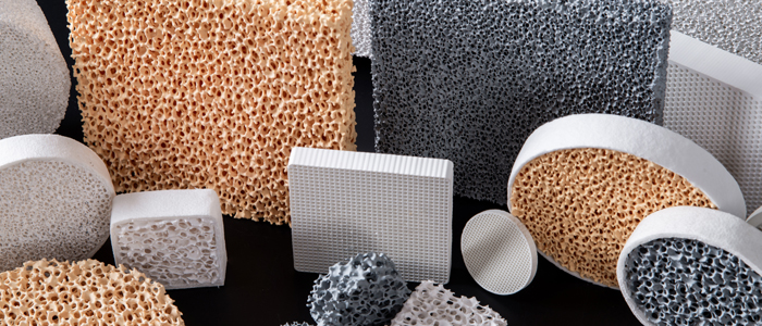
Three materials are in play: alumina (Al₂O₃), silicon carbide (SiC), and zirconia (ZrO₂). Each one owns a temperature zone. Overlap them at your own risk.
The Quick Temperature Map
| Filter Material | Typical Alloys | Pouring Temperature | Practical Upper Limit |
|---|---|---|---|
| Alumina (Al₂O₃) | High-purity aluminum | 660–780°C | ~900°C |
| SiC | Cast iron, copper alloys, general aluminum | 700–1,500°C | ~1,500–1,600°C |
| Zirconia (ZrO₂) | Steel, stainless, nickel superalloys | 1,450–1,650°C | ~1,700–2,000°C |
Where Each Material Wins
Alumina has one job: filtering high-purity aluminum where silicon contamination is not allowed. It bonds well with aluminum melt and does not release Si into the metal. For standard casting alloys, though, it falls short. Both thermal shock resistance and mechanical strength are weaker than SiC.
SiC is the workhorse. Most aluminum casting operations, cast iron shops, and copper alloy foundries use SiC as the go-to choice. It handles thermal shock better than alumina. It survives high-velocity pour conditions with fewer breaks. It holds up across multi-shift production without issues. One honest caveat: SiC filters can add trace silicon to the melt. For standard casting aluminum alloys — target Si content 6–12 wt% — the increase stays below 0.05 wt%. That level does not affect mechanical properties. For high-purity aluminum, that changes the math entirely.
Zirconia is the only option above 1,500°C. Steel, stainless steel, nickel-based superalloys — nothing else holds up at those temperatures. Stabilized ZrO₂ fights creep and softening under long, high-heat exposure. It also releases very little material into iron and nickel melts. Precision aerospace castings rely on that exact combination of stability and purity.
The Silicon Contamination Decision Point
Running high-purity aluminum or electrolytic aluminum with near-zero silicon tolerance? Choose high-purity Al₂O₃. Look for Al₂O₃ content ≥95–99 wt%, with individual impurities (SiO₂, Fe₂O₃, Na₂O) each held below 0.1–0.3 wt%.
Running general-purpose casting alloys and need thermal durability and filter strength? Choose SiC. The silicon risk is manageable. The performance advantage is real.
That’s the whole decision. Temperature first. Silicon sensitivity second. Everything else follows.
How Do You Select the Right PPI and Filter Size?
PPI is not a quality dial you turn up until satisfied. It’s an engineering tradeoff. Every point of porosity you add buys filtration efficiency and costs you flow rate.
Get that relationship wrong and you either under-filter your melt or starve your mold.
Start With Alloy and Casting Type
These numbers are specific enough to apply straight away:
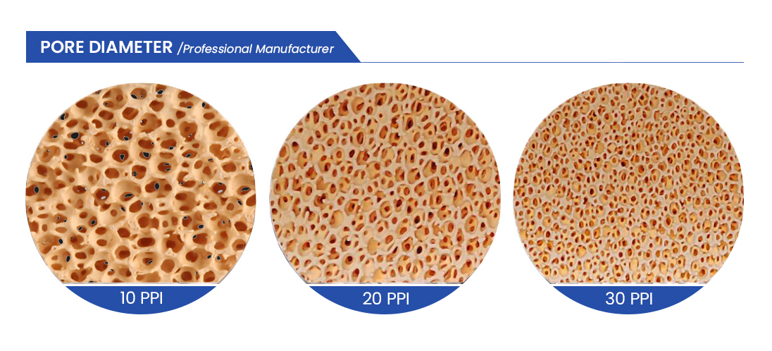
Iron and steel castings: – Steel castings: 6–10 PPI — large pores, maximum flow, captures gross inclusions – Standard Ductile Iron: 10–15 PPI – Gray iron: 20 PPI – High-quality ductile iron: 25 PPI
aluminum castings: – General sand/Gravity casting: 20–40 PPI – Structural parts with fatigue or elongation specs (≥8% elongation): 40 PPI minimum – High-quality extrusion billet and sheet: 50–60 PPI – Aerospace aluminum: 30–60 PPI — exact range depends on the specification
Pressure-rated aluminum components have a fixed minimum floor:
– Working pressure >200 bar: ≥40 PPI, no exceptions
– 50–200 bar: 30–40 PPI
– <50 bar: 20–30 PPI
Calculate Filter Area — Don’t Guess It
Calculate filter area. Don’t eyeball it. The standard formula for aluminum:
Required Area (cm²) = Pour Weight (kg) ÷ [Pour Time (s) × Specific Flow (kg/s·cm²)]
A practical example: 50 kg aluminum, 20-second pour, 30 PPI filter at 720°C with specific flow of 0.015 kg/s·cm²:
- Theoretical area: 50 ÷ (20 × 0.015) = 167 cm²
- Add 40% safety factor for progressive pore blockage: ≈234 cm²
Switch to 50 PPI and specific flow drops to around 0.010–0.012 kg/s·cm². That same pour now needs 30–50% more filter area to hold the same pour timing.
For iron and steel, use the choke-area rule: filter working area = 4–6× the gating choke cross-section. Your ingate choke is 10 cm²? Your filter face needs 40–60 cm².
Higher PPI Demands More Metal Head
Going from 30 to 50 PPI pushes pressure drop up by 30–60% across the same filter area. A gravity system gives you 200–600 mm of available metal head. That margin disappears fast.
Follow this sequence: expand filter area to 4–6× choke first. Then increase PPI. Do it the other way around and you’ll have a flow problem before filtration even kicks in.
Where Should the Filter Go in the Gating System?
Filter placement isn’t a detail you sort out after everything else is running. It’s a foundational decision. Get it wrong, and the filter does its job too late — or not at all.
The core rule is simple: the closer the filter sits to the mold cavity, the better it works. Every extra meter of open runner between the filter and the cavity gives cleaned metal another chance to pick up new oxides and bifilms. Place the filter too far upstream and you filter early — then turbulence gets another shot at undoing that work.
The Priority Hierarchy for Placement
Research across four filter positions points to the same winner: in the runner, right after the downsprue-to-runner transition, positioned toward the first ingate. That’s the practical sweet spot.
Here’s how to work through your specific setup:
- First choice — runner, near the first ingate: Works for most castings. It cuts the re-oxidation distance. It also keeps metal velocity under the 1.5 m/s threshold, which is where turbulence starts causing damage.
- Second choice — base of the downsprue: This works for single-piece castings under 100 kg with short runners and low flow volume. Not ideal, but it gets the job done.
- Skip these entirely: Mid-downsprue placement, dead-end runner positions, and any spot where the metal stream hits the filter face head-on from a vertical drop.
What to Avoid — and Why It Matters
Two placements cause problems again and again:
- Too close to the downsprue — the filter takes the full force of the vertical metal drop. That’s mechanical stress it wasn’t built for, and it breaks down filtration efficiency fast.
- At the runner end — turbulence builds up there. The filter gets hit from bad angles and clogs in patches rather than evenly.
One Filter May Not Be Enough
Pour weight changes what you need:
| Pour Weight | Recommended Setup |
|---|---|
| < 100 kg | Single filter at downsprue base |
| < 200 kg, single cavity, short runner | Single filter, downsprue or runner entry |
| Large castings, multiple ingates, long runners | Two or more filters in the runner near each ingate |
| > 10,000 kg | Ceramic foam filtration not recommended |
The Installation Detail Most Shops Miss
Leave about 1 mm clearance around the filter seat. A tight fit cracks the filter during thermal expansion. That failure is invisible — you won’t spot it until castings come out dirty and you can’t track down why. Also, if a ceramic tube connects below the filter, the open space above and below the filter face needs to be at least 3× the tube diameter.
Short version: put the filter in the runner, close to the cavity, away from direct vertical metal impact. The rest is tuning for your specific setup.
How Are Ceramic Foam Filters Installed and Preheated?
Bad installation kills a good filter. The ceramic is fine — the seat isn’t. That’s the pattern foundries repeat more than they’d like to admit.
Here’s the full sequence, broken into parts you can use on the floor.
Prepare the Seat First
The filter box must be clean and flat before the filter goes in.
- Scrape out all residual metal, slag, and refractory debris. Wire-brush the seating ledge until it looks clean.
- Check for cracks, erosion channels, or cavities deeper than 1–2 mm. Patch them with refractory mortar before anything else. An unsealed crack turns into a bypass channel. Unfiltered metal flows around the filter. Your castings come out looking like you skipped the filter completely.
- Flatness error on the support surface must stay ≤0.5 mm. Go beyond that and you get point-loading. The filter cracks along its support lines — sometimes during preheat, before metal ever reaches it.
Seat the Filter
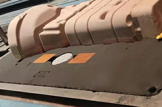
Place a refractory gasket, mud, or fiber seal strip around all four edges before lowering the filter in. The sealed gap must land between 0.5–1 mm — never over 1 mm. A gap that looks small still causes serious bypass flow under real pour pressure.
Seating contact width should be 5–12 mm around the perimeter. Narrower than that and edge crushing becomes a real risk. Wider and thermal mismatch forces start building up.
Press on all four sides with steady, even pressure. You’re confirming full 360° contact with no visible light gaps at the interface. The filter rocks more than 0.5 mm? Stop. Re-machine or re-patch the seat before you continue.
Center the filter. Don’t shift it toward the inlet or outlet face. Off-center placement pushes flow to one corner and loads the filter unevenly.
Preheat — This Step Is Not Optional
A cold filter and 700°C aluminum do not mix. You get thermal shock cracks, steam events, and metal splash. None of those are recoverable mid-pour.
Aluminum castings:
– Preheat the filter and filter box together to 500–600°C
– Ramp rate: ≤10°C/min (around 80–100°C/h in a box furnace)
– Hold at temperature for ≥30 minutes; large filters need up to 60 minutes
The target is straightforward: get the filter temperature within 100–150°C of the incoming melt. That range is what separates a clean first fill from a cracked filter and a scrapped casting.
Use an electric furnace or gas burner with a diffuser. Keep the flame off the filter face — indirect heating only. Keep the filter horizontal and level the whole time.
After preheat, check for condensation or wet spots. Any visible moisture means another 10–15 minutes in the heat before you move forward.
One hard deadline: complete installation within 10 minutes of pulling the filter from preheat. Wait longer and moisture comes back, temperature drops, and the preheat was wasted.
First Pour — Ease Into It
Don’t open full flow right away.
- Aluminum: start at 50% of normal flow for the first 2–3 seconds, then raise the head to 100–150 mm above the filter inlet face. Working head settles at 75–100 mm as flow stabilizes.
- Gray iron: press head ≥200 mm
- Stainless steel: press head ≥300 mm
Keep metal impact height at the filter face ≤150 mm for aluminum alloys. A free-fall jet above that limit creates turbulence, pulls in oxides, and can fracture the top cell layer on first contact.
The Quick-Check Numbers
| Parameter | Target |
|---|---|
| Sealed gap (filter to seat) | 0.5–1 mm, max ≤1 mm |
| Seat flatness error | ≤0.5 mm |
| Seating contact width | 5–12 mm |
| Filter area vs. gating cross-section | ≥4× |
| Aluminum preheat temperature | 500–600°C |
| Preheat ramp rate | ≤10°C/min |
| Preheat hold time | 30–60 min |
| Time from preheat to installation | ≤10 min |
| Initial metal head (Al) | 100–150 mm |
| Impact height on filter face (Al) | ≤150 mm |
The filter does its job when everything around it is set up right. Seat prep, sealing, preheat temperature, hold time, first-pour head — each one is a link in the chain. Break any of them and the filter takes the blame for a problem it didn’t cause.
Can Ceramic Foam Filters Remove Gas Porosity and Dissolved Hydrogen?
Ceramic foam filters do not remove dissolved hydrogen. That’s the short answer. It doesn’t change based on filter grade, pore size, or supplier claims.
Filters remove solid inclusions — oxides, bifilms, slag, dross. Confusing “less porosity” with “less hydrogen” is where most diagnostic errors begin.
What the Data Shows
Controlled trials used 20, 30, and 40 PPI alumina filters in aluminum alloys. The average hydrogen content difference upstream versus downstream was 0.008 ml/100 g Al. That number falls inside instrument uncertainty. Dissolved hydrogen stayed unchanged before and after the filter.
But at a constant 0.15 ml/100 g Al hydrogen level, a 30 PPI filter cut the Porosity Index from 4.8 down to 2.9 — a ~40% drop with the same hydrogen content. Meta-review data backs this up: 25–45% gas porosity reduction is achievable through bifilm removal and flow calming. Not hydrogen removal.
The mechanism is straightforward. Bifilms are the preferred nucleation sites for hydrogen bubbles. Take away the bifilms, and the same hydrogen concentration produces fewer pores. The hydrogen stays in the melt. The trigger is gone.
Where Degassing Fits In
Gas porosity needs a two-step fix:
- Degassing unit (rotary or vacuum): strips dissolved hydrogen from ~0.25–0.30 ml/100 g Al down to the target ≤0.10–0.15 ml/100 g Al
- Ceramic foam filter: placed after degassing, removes remaining inclusions and smooths mold fill
Neither step replaces the other. A process spec that relies on filtration alone to hit hydrogen porosity targets is built on a false assumption.
Practical Diagnostic Logic
Seeing gas porosity and need to find the cause? Work through it this way:
- Measure melt hydrogen before the filter. H > 0.15–0.20 ml/100 g Al means degassing needs attention first — check rotor speed, gas flow, and treatment time.
- Compare porosity with and without the filter at the same hydrogen level. A 25–40% drop tells you bifilms and turbulence were the main problem, not hydrogen concentration.
- Porosity stays high despite the filter? Hydrogen is probably still too high. Check furnace atmosphere and charge moisture for hydrogen pickup sources.
Use filters for inclusion control and flow conditioning. Use degassing for hydrogen. Both tools work together — they don’t do the same job.
How Often Should Filters Be Replaced, and Can They Be Reused?
One pour, one filter. That’s the rule.
Ceramic Foam filters are single-use only. This isn’t a manufacturer upsell — it’s physics. After one pour, the internal strut network fills up with trapped inclusions, oxide films, and solidified metal fragments. These go deep into the cell structure. You can’t clean them out. You can’t burn them off. The path that made the filter work is now blocked and broken.
Try to reuse a ceramic foam filter, and three things go wrong:
- Bypass channels form. Flow piles up around clogged zones. It finds easy paths through weakened strut walls. The filter looks fine. It isn’t filtering.
- Trapped inclusions break loose. Pressure shifts during a second pour can knock trapped particles back into the melt stream. That’s the opposite of filtration.
- The structure breaks down faster. The first pour creates micro-cracks from heat stress. A second heat shock makes them worse. Fracture risk jumps sharply.
The Replacement Signal to Watch
Make the replacement call before the pour, not during it. Check these three things:
- Any visible cracking, chipping, or surface flaking → replace it now
- Prior pour contact of any kind → replace it, no exceptions
- Storage beyond 6 months in humid or dirty conditions → run the light test; replace if light passes through unevenly
One filter, one pour. The cost of a cracked casting always beats the price of a fresh filter.
What Are the Most Common Filtration Failures and How Do You Avoid Them?
Four failure modes cause most ceramic foam filter problems in production. They’re predictable. They’re preventable. And they leave the same fingerprints every time.
Failure 1: PPI Too Fine — Filter Won’t Prime
The melt hits the filter face and stops. Mold fill is incomplete. Back-pressure builds. The casting misfills at the front.
This is a hydraulics problem, not a filter quality problem. A 30 PPI alumina filter needs a minimum 100–150 mm metal head above the inlet face to prime. Drop below that without raising the head, and flow resistance wins.
Two things make it worse:
– Melt temperature below 720°C — viscosity increases, surface tension spikes
– A cold filter — a surface skin forms on first contact and never breaks free
Fix it: Hold head at ≥150 mm for 30 PPI. For finer grades, push to 200–250 mm. Priming failures keep repeating? Drop one PPI grade coarser, or increase filter area to cut resistance. Keep melt temperature in the 720–780°C window.
Failure 2: Filter Media Contamination
Ceramic chips in the casting. Inclusion counts rising after the filter went in. That’s media shedding — and it traces back to the supplier’s kiln, not your process.
Under-fired filters are weak and spall. Over-fired filters are brittle and crack. Both shed particles into the melt.
What to require from suppliers:
– Documented firing curves
– Batch inspection data covering PPI, dimensions, weight, and appearance
– Compressive strength ≥1.5 MPa and temperature resistance ≥1,000°C on statistical samples
Reject anything with visible edge chipping, inconsistent pore structure, or abnormal weight.
Inclusion counts rise after a filter changeover? Suspect media shedding first. Pull the supplier’s firing records and mechanical test data before calling it a process problem.
Failure 3: Turbulence at the Filter — Cracking, Erosion, Bypass
Too much velocity through the filter creates three problems at once:
– Fracture from pressure spikes
– Re-oxidation from splashing downstream
– Bypass flow through gaps opened by cracking
Target flow velocity is 0.5–1.0 m/min. Go past that and you’re outside the filter’s design range. Most gating systems need a filter area between 0.1–0.3 m² — sized to hold velocity within that range.
Past that threshold, replace the filter after 50–80 tons processed. Replace it sooner if pressure differential across the filter exceeds 0.08 MPa.
Layout fixes to apply:
– Avoid vertical drops after the filter
– Use expanding runners
– Seal the filter box with ceramic fiber gaskets
– Design for gradual cross-section changes within two to three hydraulic diameters of the filter face
Failure 4: Premature Saturation and Hidden Bypass
Back-pressure builds mid-pour. Fill rate drops. Melt starts routing around clogged zones through weakened strut channels. The filter is still in the box — it just isn’t filtering anymore.
This happens for three reasons: inclusion load is high, filter area is undersized, or PPI is too fine for a dirty charge.
The upstream fix matters most here: run rotary degassing with argon or nitrogen at 5–15 L/min, rotor speed 350–500 rpm, treatment time 8–12 minutes for a 500 kg ladle. For recycled or contaminated charge, run two-stage filtration — 20–30 PPI coarse first, then 40–50 PPI fine.
Pressure differential approaching 0.08 MPa? Back-pressure rising more than 50–100% above clean baseline during a pour? Increase filter area before the next heat. Not after.
How Should Ceramic Foam Filters Be Stored and Handled?
Ceramic foam filters fail before they ever touch molten metal. The damage happens in the warehouse, on the transport cart, or in someone’s hands — before the pour even starts.
Storage Conditions That Matter
Keep RH below 60%. That’s the hard line. Moisture soaks into the ceramic matrix. On contact with molten aluminum, it turns to steam. Steam events mid-pour are not fixable.
Practical targets:
– Temperature: 4–32°C
– Humidity: ≤60% RH, logged each day
– Floor clearance: 10–15 cm minimum — concrete pulls moisture into packaging
– Light exposure: covered or boxed; UV breaks down the ceramic binder over time
Keep filters away from wash stations, launder areas, and casting floor doors. Steam and splash compromise sealed packaging fast. Faster than most people expect.
Shelf Life and Stock Rotation
Practical shelf life under dry, sealed storage: 2–3 years. Past that point, oven-dry at 200–300°C for 30–60 minutes before preheating. Run FIFO rotation — date every pallet on arrival and assign an internal expiry. Old stock hiding behind new stock is how expired filters end up in the pour. Nobody notices until something goes wrong.
Handling Without Breaking Things
Ceramic foam handles compression well. Everything else — drops, flex, bad grips — can crack it. One wrong grip creates a hairline crack. That crack skips filtration and shows no sign of damage at installation.
The rules are short:
– Carry by the edges. Never grip the filter face or center.
– Never drop, toss, or slide filters across hard surfaces.
– Transport one layer per padded tray. No bare stacking.
– Open packaging at the installation station only — not at the rack, not in transit.
Pre-Installation Inspection
Every filter gets a visual check before it goes in. No exceptions.
- Inspect sealing edges, corners, and both faces for cracks, chips, or broken struts
- Blow off dust with clean dry compressed air — nozzle at least 10 cm from the surface
- Reject anything with visible moisture, staining, or edge damage
- Check the storage record. RH exposure above 60%, or age past three years? Oven-dry at 200–300°C for 30–60 minutes, then preheat to 260–500°C for 15–30 minutes before installation
Most storage failures stay hidden. A filter can look clean on the outside and still hold enough absorbed moisture to trigger a steam event on first contact. Visual checks alone are not enough. That’s why the inspection step and the drying step both exist.
How Do You Build a Systematic Foam Filtration Optimization Process?
Optimization without measurement is just guessing with better equipment.
A real filtration process needs three things working together: a cleanliness target you can measure, a data system that captures what happens every heat, and a verification loop that closes the gap between what you planned and what you got. All three must work together. Miss one, and the process breaks down.
Set a Cleanliness Target First
Define what “clean enough” means for your casting before you touch PPI or filter area. The target shifts by application:
| Part Class | Max Inclusion Size | Area Fraction |
|---|---|---|
| Decorative / non-structural | ≤50 µm | ≤0.05–0.1% |
| General industrial structural | ≤20–30 µm | ≤0.02–0.05% |
| Aerospace critical | ≤10–20 µm | ≤0.01–0.02% |
Match those targets to filter grade:
– 10–20 PPI: coarse slag capture, suitable where ≥50 µm inclusions are acceptable
– 30 PPI: standard aluminum castings, targets 20–30 µm
– 40–60 PPI: aerospace and thin-wall parts, pushes toward 10–20 µm
Record the Right Data Every Heat
Track these fields — no exceptions:
- Filter material, PPI, nominal size, and effective face area
- Metal mass per mold, melt temperature, available head, target fill time
- Pre- and post-filter inclusion metrics: average size, maximum size, area fraction, count per mm²
- Defect rate per batch (%) and dominant defect type
- Mechanical test results — UTS, yield strength, elongation — tied to the specific filter configuration
Run at least 7–10 consecutive heats with the same template before you draw any conclusions. Trends need consistent, comparable data to show up. Fewer heats give you noise, not signal.
Close the Loop With Mechanical Performance
Post-filter inclusion counts tell you what the filter caught. Mechanical test data tells you whether it mattered.
Upgrading from wire mesh to 30 PPI foam is a good starting point. Pair that with a +15°C pour temperature adjustment to offset filter heat absorption. That combination gives you a 3–10% tensile strength improvement and a 10–30% elongation gain. Results vary by alloy and baseline inclusion load, but the direction is reliable.
Defect rates staying high despite filtration? Add a two-stage setup: 20–30 PPI coarse filter first, then 40–50 PPI fine. That sequence works well for contaminated or recycled charge material. A single filter saturates too fast under that kind of load.
The process compounds. Each batch of clean data makes the next adjustment easier to justify — and harder to argue with.
Conclusion
Every question in this FAQ points to the same truth. Ceramic foam filtration isn’t a passive step in your process. It’s an active quality decision — made dozens of times before metal ever touches the mold.
The mistakes are easy to make. Wrong material for your alloy. Filter placed in the wrong spot in your Gating System. Skipped preheat. Filters stored without care. Any one of these costs you the casting before the pour even starts.
Get these basics right, though, and something changes. You start cutting out the inclusion-related defects that drain real money, real time, and real customer trust from your foundry. Not through luck — through repeatable process control.
That’s what ceramic foam filters deliver. No magic. Just the right tool, placed correctly, handled properly, at the right moment in your process.
So start with one thing: find where your filtration is breaking down right now. Audit it. Be specific. This guide gives you the diagnostic framework to work through it — defect by defect, step by step.
Better castings aren’t accidental. They’re built on purpose.