

Pick up a ceramic foam filter and you’ll notice something right away — it looks almost identical to the foam padding inside a shipping box. That’s not a coincidence.
The journey from sponge to filter is one of manufacturing’s most elegant transformations. A polyurethane template burns away, leaving behind a ceramic skeleton in its exact shape. Clean. Precise. Built to last.
So how are Ceramic foam Filters made, and what separates one that holds up under 1,400°C molten metal from one that breaks down at the worst moment?
The answer comes down to seven well-defined steps — from slurry chemistry to sintering temperatures. Each step has its own logic, its own failure points, and its own impact on final performance. Understanding all seven changes how you evaluate filters, how you specify them, and how much confidence you put in the ones going into your casting line.
What Is a Ceramic Foam Filter (And Why the Sponge Matters)
A Ceramic foam filter is a 3D porous ceramic structure — open-celled, interconnected, built to catch unwanted particles in molten metal.
Think of it as a ceramic sponge with a job to do. Total porosity runs 20–95%, and pore size is measured in PPI — pores per inch. Standard Foundry filters range from 10 to 60 PPI. Coarser cells push more metal through faster. Finer cells trap smaller inclusions. That one number controls a huge amount of what happens inside your casting.

Material choice follows the metal you’re pouring: – Alumina (Al₂O₃) — aluminum alloys – silicon carbide (SiC) — cast iron and steel – Zirconia (ZrO₂) — high-alloy steel, rated to 1,600°C
Filtration isn’t simple sieving, either. CFFs work through three distinct mechanisms:
– Size exclusion — larger particles get blocked at pore throats
– Deep-bed adsorption — fine oxides and films stick to internal strut surfaces
– Cake filtration — early-caught inclusions build up a layer that traps even finer particles further down
The result? Industry data shows 30–80% lower inclusion counts compared to unfiltered gating systems. Critical aluminum castings pick up 5–20% tensile strength improvement after switching from mesh screens to CFFs.
Why the Sponge Is the Real Starting Point
The Polyurethane foam isn’t just packaging material. It’s the structural template for everything the ceramic filter becomes.
Its cell size, uniformity, and open-cell layout transfer into the finished ceramic network. Every closed cell matters. Every density shift matters. Every flaw in the original PU foam shows up later — as a dead zone, a channeling path, or a weak strut under heat load.
That’s why the sponge matters before the ceramic ever does.
Step 1 – Selecting and Preparing the Polyurethane Sponge Template
The sponge you choose determines the filter you get. Full stop.
PPI is the first decision — and it drives everything downstream. Lower PPI means larger cells, faster slurry penetration, and less flow resistance. Higher PPI means tighter pore control, slower fill, and finer structure.
The practical breakdown:
– 10 PPI — maximum openness. Best for thick slurries, aluminum castings, and cases where blockage is a bigger risk than pore precision
– 20 PPI — the workhorse setting. Balanced flow and filtration, most common across iron and copper applications
– 30 PPI — fine control territory. Slower penetration, tighter replication. Choose this when pore definition matters more than speed
Metal type narrows the choice further. Aluminum works with 10–20 PPI. Iron and steel need 20–30 PPI. Copper falls somewhere in between.
Preparation Before Impregnation
Three things must happen before a drop of slurry touches the foam.
Cut with precision. Trim to your final target dimensions with tight tolerances. Sloppy edges distort the geometry of the finished filter. There’s no fixing that later.
Clean the surface. Dust and debris break uniform wetting. One contaminated cell turns into a dead zone.
Test the rebound. Compress the sponge, release it, and watch what happens. It stays flattened? Reject it. Low resilience leads to uneven impregnation and inconsistent pore transfer. Those two problems grow worse at every step that follows.
Producing foam in-house? Keep your mixing speed at 2,000–6,000 rpm and your isocyanate index between 90–110. Drift outside those ranges and cell stability breaks down — before the ceramic process even starts.
Step 2 – Formulating the Ceramic Slurry (The Core of Performance)
The slurry is where material science earns its keep.
All that work in Step 1 — the pore count, the foam geometry, the careful preparation — means nothing if the ceramic slurry is off. Get this wrong and you’re not making filters. You’re making expensive gravel.
The slurry is a mix of ceramic powder suspended in water, combined with binders, sintering aids, and dispersants. But the ratios drive everything. Total solid content runs 60–75 wt% for impregnation-grade slurries. Drop below that and the coating won’t hold. Go above it and the pores start to close.
Ceramic Powder: Match the Metal
The main solid in your slurry follows the same material logic from Step 1 — but now you’re locking it into chemistry:
-
Alumina (Al₂O₃) — makes up 80–95 wt% of the solid fraction for aluminum and non-ferrous applications. It’s cost-effective, stable against aluminum melt, and straightforward to process.
-
Silicon carbide (SiC) — same 80–95 wt% range, but built for iron and steel at 1,350–1,600°C. Add oxide sintering aids (Al₂O₃, Y₂O₃, MgO) at 3–10 wt% of solids. These push high-temperature strength and thermal shock resistance.
-
Zirconia (ZrO₂) — for high-alloy steel and tough refinery applications above 1,600°C. ZrO₂ takes up 70–90 wt% of solids. You stabilize it with 3–8 mol% Y₂O₃ to block the phase transformation that breaks down unstabilized zirconia under thermal cycling.
Particle size matters too. Alumina powders for foam filter slurries target a D50 of 1–10 μm. Fine enough for solid pore coating and surface adhesion. Coarse enough to stay suspended without constant stirring.
Binders, Aids, and the Supporting Cast
Ceramic powder alone won’t bond to polyurethane foam. You need binders — and the right mix of them.
Inorganic binders (colloidal silica is the standard choice) make up 15–35 wt% of total slurry mass. They connect green strength to fired strength.
Organic binders (PVA is the most common) add 3–6 wt% relative to ceramic powder. That’s enough to boost green-body adhesion during drying. It also avoids leaving heavy carbon residue after burnout.
Sintering aids depend on your material type. SiO₂ or glass powder at 3–15 wt% of solids keeps alumina systems sinterable at practical kiln temperatures. Keep total additive loading below 15 wt% of solids. Past that point, high-temperature corrosion resistance drops off.
Viscosity: The Number That Controls Everything Downstream
Target 0.3–1.5 Pa·s at shear rates of 10–100 s⁻¹. That range holds flowability and wall-adherence in balance — the two competing demands of foam impregnation.
Too thick and the slurry blocks pores. A 20–30 PPI foam should gain 40–70 wt% during impregnation. Seeing weight gain above 80 wt% on a regular basis? The slurry is too viscous — or your squeeze step needs adjustment.
Too thin and the slurry leaves a weak coating. Weight gain falls below 70–80% of target. After sintering, the struts come out thin, porous, and fragile.
Dispersants (polyacrylates, polyphosphates) at 0.2–2 wt% of ceramic powder stop particle clumping. Bentonite at 0.5–3 wt% of total slurry creates thixotropic behavior. That’s what keeps the coating in place — rather than draining out the moment the foam clears the bath.
Step 3 – Immersion Coating: Getting the Slurry Into Every Cell

The slurry is ready. The sponge is prepared. Now comes the step where everything either comes together — or falls apart without warning.
Immersion coating sounds simple. Dip the foam, pull it out, move on. But the physics inside those tiny pores push back the whole time. Air has to escape. Slurry has to penetrate. The coating must reach every internal strut — but it cannot seal the cells shut.
Soak time is a tighter window than most people expect:
-
1–3 seconds achieves >90% full-cell wetting with pore blockage below 2–3%
-
Push beyond 5–10 seconds and blockage climbs to 5–10% — this gets worse with high-solids slurries above 65 wt%
-
Pores finer than 0.3 mm? Use 1–2 second dips repeated 2–3 times, with intermediate drying between each pass
Single Dip vs. Multiple Passes
One immersion is not enough. A single dip delivers 50–70% of target coating thickness at best. The standard industrial approach uses two passes with intermediate drying. This brings thickness to 90% of design value and cuts thickness variation (CV) from 8–10% down to 4–6%.
Three passes can close that gap further — CV drops to 3–4% — but pore blockage risk rises fast. Most production lines go with two dips plus a diluted third-pass slurry instead of three full-strength passes. It’s the safer trade-off.
The quality check is straightforward: measure pressure drop across the coated foam against an uncoated blank. A pressure increase of 10–20% means open cells and good flow. Above 30%? Blockage is above 5–10% — and that calls for process adjustment. Don’t count on the sintering step to fix it.
Step 4 – Squeezing Out Excess Slurry (The Pore-Defining Moment)
After immersion, the foam is fully saturated. Every cell is packed with ceramic slurry, and open porosity is gone. That’s the problem. Controlled compression is the fix.
Squeezing is where pore geometry gets locked in. Too little pressure and residual slurry chokes the channels. Too much and the struts crack before the kiln ever fires. The working window is narrow.
Compression strain targets: – ε ≈ 0.2–0.3 — light squeeze. Coating thickness lands at ~250–350 μm, porosity at 70–80%. Best for high-retention filtration where flow rate is secondary – ε ≈ 0.4–0.5 — the standard casting filter range. Coating thins to 120–200 μm, porosity rises to 80–90%. Most steel and aluminum filters are made here – ε > 0.6 — danger zone. Struts fracture. Coatings strip thin. Porosity climbs above 90%, but mechanical strength collapses
Contact pressure on soft PU foam stays between 10–50 kPa. Go past 100 kPa and breakage becomes routine.
Rolling vs. Centrifugal Removal
Two methods lead in production. Each suits different situations.
Rolling uses press rollers at 0.1–0.5 m/s with rubber-covered surfaces (5–20 mm layer). That rubber layer cushions stress peaks. Line pressure runs 0.5–5 kN/m. Running multiple passes in alternating directions cuts coating thickness variation by 10–20%. The setup is simple and works well on large flat filters.
Centrifugal spinning runs at 800–1,500 rpm for 30–120 seconds. It generates 40–250g of acceleration. That force pulls slurry out of pore centers without putting concentrated stress on the structure. You get better thickness uniformity in a single cycle. The tradeoff: higher equipment cost and less flexibility with complex geometries.
Hold each squeeze cycle for 1–5 seconds. Past 10 seconds, returns drop fast — you might pull out 5% more slurry, but cycle time stretches well beyond what that gain is worth.
Get the compression right and porosity hits 80–90%. Air permeability sits at 1×10⁻¹¹–1×10⁻¹⁰ m². Stop too soon and permeability drops a full order of magnitude. The casting line will feel that flow resistance right away.
Step 5 – Drying the Green Body
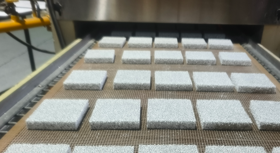
The coated foam is fragile now. More fragile than it looks.
Moisture still fills the ceramic coating, and that moisture is a real problem. Rush the green body, blast it with heat, or let the surface dry faster than the interior — stress fractures form before the kiln ever fires.
The fix is patience. Drying happens in a closed or semi-closed environment over 20–30 hours. That long window exists for one reason: moisture-gradient stress. The outer surface sheds water faster than the interior can match. That tension warps struts, opens cracks, and destroys parts that look perfectly fine from the outside.
Practical controls that matter:
– Temperature stays in the 60–120°C range — warm enough to push moisture out, slow enough to keep gradients under control
– Humidity stays moderate — drop it too low and the surface hardens on the outside while the core stays wet inside
– Thick filters need longer cycles, not hotter ones
How do you know it’s done? Weight stability. The part stops losing mass between checks — that means moisture is gone. Then do a quick handling inspection — check edges, surfaces, and geometry. Visible cracks, chips, or warpage means rejection happens now, before sintering, not after.
Step 6 – Burnout: Eliminating the Sponge, Revealing the Skeleton
The polyurethane has done its job. Now it has to disappear.
This step sets ceramic foam filter manufacturing apart from almost every other ceramic process. You’re not just firing a shape into permanence. You’re destroying the template that created the shape — while keeping the ceramic shell it left behind fully intact.
Get it wrong and that shell cracks apart before it ever sees a furnace charge.
What Actually Happens Inside the Kiln
Polyurethane foam doesn’t vanish in one clean sweep. It breaks down in stages. Each stage creates its own hazards for the ceramic coating surrounding it.
The thermal decomposition follows a clear pattern:
-
25–250°C — moisture and residual solvents escape. Mass loss is small: around 1–5%
-
250–350°C — hard segment depolymerization begins. Urethane and urea bonds break down, releasing isocyanates, amines, and CO₂. Mass loss hits 20–40% in this window alone
-
350–450°C — soft segment cracking speeds up. Combustible gases form. Cumulative mass loss reaches 70–90% of total organic content
-
450–600°C — residual char oxidizes. Final carbon content drops to <5–10 wt% under normal air atmosphere
That progression isn’t the problem. The rate at which you push through it is.
Why Ramp Rate Is the Variable That Kills Filters
Fast PU decomposition doesn’t just remove the foam. It creates a sudden burst of volatile combustion gases — trapped inside a ceramic structure that hasn’t yet reached anywhere near full strength. Green-body tensile strength at this stage sits at just 5–20% of final sintered values. Internal gas pressure builds faster than the walls can absorb it.
The result: cracking, delamination, and blowout fractures — all before the filter reaches peak firing temperature.
The physics are simple. Internal pressure follows:
P ≈ nRT/V
A high ramp rate drives both gas generation (Δn/Δt) and temperature (ΔT/Δt) up at the same time. Pressure spikes. The ceramic skeleton, still weak and only partly bonded, can’t hold. Thick-walled or large-volume filters make this worse — the core temperature lags the surface by 20–50°C, stacking thermal stress on top of gas pressure stress.
Industrial ramp rate standards address this head-on:
-
100–200°C zone — keep the ramp to 0.5–1.0°C/min, or use stepped isothermal holds (1–2 hours every 50°C increment) to clear moisture and solvents at a controlled pace
-
250–400°C zone — the danger window. Drop the ramp rate to ≤0.5–1°C/min, with 2–4 isothermal holds at staged temperatures (280°C, 320°C, and 360°C are common targets, each held for 1–3 hours depending on part size)
-
Filters larger than 1 L or thicker than 10 mm — the full burnout stage, from room temperature through 600–650°C, runs 24–48 hours total
Rushing that schedule doesn’t save time. It scraps the batch.
Managing What the Sponge Leaves Behind
Burning PU foam in a kiln produces more than CO₂ and water. The exhaust stream carries CO, uncombusted hydrocarbons, amine decomposition products, NOₓ, and isocyanate fragments. CO concentrations during peak decomposition can hit thousands of ppm in localized oxygen-deficient zones.
Kiln exhaust systems for burnout operations are built around this reality:
-
Furnace gas exchange: the entire kiln atmosphere turns over once every 5–10 minutes during peak decomposition, stopping combustible gas from building up
-
Secondary combustion chamber: exhaust gases stay above 650–750°C for at least 2 seconds, converting >95–99% of CO and breaking down VOCs before atmospheric release
-
Emissions targets after treatment: CO below 100 mg/m³, total hydrocarbons below 50–100 mg/m³, ceramic particulate below 10–30 mg/m³
-
Online monitoring: O₂, CO, and temperature sensors run in the flue gas line. CO above 1,000 ppm triggers automated controls — either combustion air increases or the heating rate drops
What a Complete Burnout Looks Like
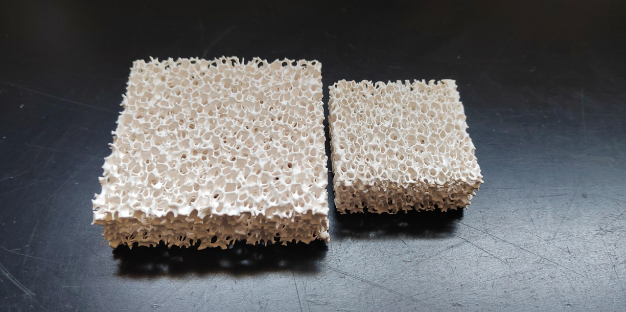
A clean burnout leaves a clean ceramic skeleton. Cross-sections show no dark carbon cores, no organic residue in the strut interiors — just the three-dimensional ceramic lattice the PU foam once defined.
The numbers describing that skeleton are familiar from earlier steps. Now they’re fixed for good:
-
Open porosity: 85–90% for standard casting filters
-
Strut diameter: 0.2–1.5 mm, set by the original slurry solid content (60–80 wt%) and squeeze parameters from Steps 3 and 4
-
Bulk density: 0.3–0.8 g/cm³, with compressive strength between 0.5–4 MPa at room temperature
A black core in a cross-section at this stage isn’t a cosmetic flaw. Incomplete burnout means organic residue stays locked inside the struts. That residue weakens high-temperature strength and thermal shock resistance — the two properties that decide whether a filter survives contact with molten metal.
Not clean here means it won’t perform there.
Step 7 – High-Temperature Sintering: Building Strength and Structure
Burnout leaves a skeleton. Sintering turns it into armor.
The ceramic lattice in the kiln after Step 6 is fragile. Open porosity sits above 85%. Compressive strength measures in fractions of a megapascal. The next several hours change all of that. High temperature forces ceramic particles to bond, densify, and lock into a structure that survives direct contact with molten metal above 1,400°C.
The temperature target depends on which ceramic you’re firing:
-
Alumina (Al₂O₃): 1,200–1,600°C for pressureless sintering. High-purity grades go above 1,500°C to reach ≥98% theoretical density. Watch grain growth above 1,500°C — grain size can jump from 1–2 µm to over 5 µm. Strength drops once coarsening takes over from densification.
-
Zirconia (ZrO₂): The numbers say it clearly. Sintering at 800°C yields 55% relative density and 9.3 MPa flexural strength. Push to 1,450°C and both figures change — 98.3% density, 356.1 MPa strength. That’s a 38× increase driven by pore closure and controlled grain size, not by material change.
-
Silicon carbide (SiC): Pressureless sintering needs above 2,000°C — often 2,050–2,200°C — with boron or carbon sintering aids. Liquid-phase-assisted routes can work around 1,900°C. There’s no shortcut to the temperatures SiC requires.
Hold Time, Atmosphere, and the Density Threshold That Matters
Peak temperature hold time runs 1–4 hours for Oxide ceramics. Shorter holds at higher temperatures can hit similar density targets — but they risk abnormal grain growth. That grain growth silently wipes out the strength gains sintering was meant to build.
Atmosphere isn’t optional chemistry. It’s structural.
-
Oxide ceramics (Al₂O₃, ZrO₂): Fire these in air or an oxidizing atmosphere. Keep oxygen partial pressure above 10⁻¹ atm. This stabilizes oxide phases and blocks reduction reactions that would weaken the ceramic in service.
-
SiC and non-oxide ceramics: Use inert atmospheres — argon or nitrogen — with oxygen content below 10–100 ppm. At these temperatures, oxidation doesn’t protect the surface. It breaks it down.
The critical density threshold sits at 90–95% of theoretical density. Below that line, open porosity still runs through the strut network and sintering stress keeps pushing densification forward. Cross that line and pores close off, become isolated, and the sintering mechanism stops — not because something went wrong, but because the framework is now strong enough to resist further compaction. At that transition point, Step 7 locks in the filter’s final pore shape, mechanical strength, and thermal shock resistance.
Get the temperature right and hold the atmosphere steady. The ceramic foam filter that comes out of the kiln is a different object from the one that went in. The sponge is gone. What remains is built to work.
The Final Product: Structure, Pore Ratings, and What They Mean in Practice
Seven steps of chemistry, heat, and controlled destruction — and what comes out the other end is a number stamped on a data sheet: 10 PPI, 20 PPI, 30 PPI. That number is small. What it controls is not.
PPI sets the pore throat size. Pore throat size decides what the filter catches. For aluminum casting, 10–20 PPI handles standard gravity pours. Move up to 25–30 PPI and finer inclusions start getting trapped. Cast iron runs on 10–20 PPI — push it higher and the iron melt backs up. Steel and high-alloy work needs 20–30 PPI. At that range, capture efficiency justifies the tighter flow. High-precision jobs push to 40–60 PPI. Blockage risk and pressure drop climb fast at that level.
Open porosity locks in the flow-strength balance. Aluminum filters sit at 80–90%. Iron and steel filters drop to 75–85%. Less open space means thicker struts. Thicker struts give better resistance to thermal shock and static pressure.
Material determines what the finished filter looks like — and how far it can push:
-
Al₂O₃ filters — pale yellow to ivory, 0.35–0.65 g/cm³, room-temperature MOR of 0.6–1.5 MPa. Built for aluminum, rated to 1,350°C.
-
SiC filters — dark gray to black, clearly heavier than Al₂O₃, MOR of 1.0–2.5 MPa. Built for iron, holds up to 1,450–1,500°C.
-
ZrO₂ filters — off-white, densest of the three at 0.50–0.90 g/cm³, MOR reaching 3.5 MPa at room temperature. Built for steel, rated above 1,600°C.
Three filtration mechanisms do the work — surface sieving, cake filtration, and depth capture. Each one kicks in at a different point. Surface sieving leads for the first 10–30 seconds. It pulls out particles above 100–200 μm and cuts coarse inclusion volume by 60–90%. Trapped inclusions then build a 1–5 mm cake layer at the inlet face. That cake layer shrinks the effective pore size from millimeters down toward 10 μm. So you get another 30–60% reduction in mid-size particles. Deep inside the strut network, inclusions in the 10–50 μm range hit curved flow paths and bond to internal surfaces. At 25–30 PPI with 80–90% open porosity, capture rates for particles above 30 μm reach 70–90%.
One number on a label. Seven steps behind it. Every casting it touches, it earns that number.
How Ceramic Foam Filters Are Used in Metal Casting
A filter placed in the wrong position does almost nothing. That’s the part most people don’t talk about enough.
Ceramic foam filters belong in the gating system — in the runner before ingates, at the sprue base, in the pouring cup, or inside a dedicated filter box. The core rule is simple: place it as close to the mold cavity as possible. Every inch of travel after the filter gives the metal another chance to pick up contamination.
Placement alone isn’t enough. The filter seat must force all melt through the foam — no bypass paths, no gaps. Build the Gating System with no back-pressure shortcuts. Keep the narrowest cross-section in front of the filter, not behind it. A jet effect past the filter face kills the entire purpose.
Two sizing rules worth memorizing:
– Filter area should run 2–4× the gating choke area to keep flow stable and cut clogging risk
– Match PPI to the job: 10–20 PPI for large castings needing high flow, 20–30 PPI for medium filtration, 40–50 PPI for fine inclusion capture
The filter traps oxides, slag, sand, and refractory debris. But it also does something harder to measure — it calms the melt. Turbulent flow turns laminar. New oxide films stop forming. The cavity fills in a steady, controlled way rather than a chaotic one.
Head pressure matters here. Too low and the filter primes at a sluggish rate, risking cold shuts and misruns. Too high and the force of impact damages the filter face head-on.
Ceramic foam filters work best as the final polishing step in a clean system. They are not a fix for poor melt practice or a poorly designed gating setup.
Key Quality Factors: What Separates a Good Filter from a Great One
Most ceramic foam filters will do the job. Very few hold up batch after batch, under the full thermal stress of molten metal contact.
The difference isn’t visible from the outside. It lives in the numbers.
Pore uniformity is the first real separator. Great filters have narrow pore size distributions — standard deviation under 10–15% of mean pore size. Wide distributions create bypass channels. Bypass channels let inclusions slip through at the worst possible moment. Serious manufacturers verify this with bubble-point testing and capillary flow porometry — not just at final inspection, but lot to lot.
Thermal shock resistance is where ceramic foam filters earn or lose their reputation. A great filter survives rapid thermal gradients above 800–1,200°C without cracking. The benchmark test is brutal by design. You preheat the filter, pour molten metal over it, and repeat five or more cycles. Great filters show no visible cracks and less than 5–10% permanent flow loss after all that. Good filters crack on cycle three.
Mechanical defect thresholds tell you what a supplier truly controls:
-
Crack defect rate at incoming inspection: < 0.5–1%
-
Flow rate variation across a batch: within ±5% of nominal
-
Coating adhesion: < 5% mass loss after repeated backflush cycles
Beta stability over service life settles the argument. A good filter might drop 10–20% in capture efficiency as it loads toward terminal pressure drop. A great filter keeps beta variation within 5–10% from clean to near-terminal. That’s because the media stays supported, the pores stay bonded, and the structure holds firm under load.
One number on a data sheet never tells the full story. You pick great filters by looking at several metrics together.
Conclusion
A humble polyurethane sponge goes in. One of the most precise filtration components in modern metal casting comes out. Now you know why.
The journey from sponge to filter is more than a manufacturing curiosity. Every decision in the process — slurry chemistry, squeeze pressure, sintering temperature — shapes the final result. Get those decisions right, and you get a filter that performs. Get them wrong, and the cost shows up fast. The gap between a good filter and a great one lives in details most buyers never think to ask about.
That gap matters. In casting, the filter isn’t a footnote. It’s the last line of defense between clean metal and a scrapped part.
So here’s your next move — don’t just compare price per piece. Ask the supplier real questions:
-
Where do the raw materials come from?
-
What pore uniformity standards do they hold?
-
What sintering protocols do they follow?
The manufacturers who answer those questions with clarity and detail? Those are the ones worth talking to.
The sponge disappears in the process. Your quality doesn’t have to.