Every casting defect tells a story — and shrinkage porosity is the one that stings the most. You poured it right. The mold looked clean. But somewhere in that solidification window, the metal pulled inward and left a void where strength should have been. Nine times out of ten, the riser is why it failed — or why it didn’t.
Knowing the top 10 types and applications of risers in casting goes beyond textbook knowledge. It’s the difference between a part that ships and a part that gets cut open on the quality table. This guide covers every major riser type — from gravity-fed top risers on heavy steel pours to exothermic sleeves tackling shrinkage on complex shapes. You’ll see what each one does, where it fits, and why it works.
What Is a Riser in Sand Casting
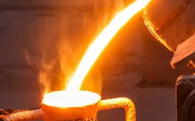
A riser is a reservoir of molten metal built into the mold. Its only job is to feed the casting as it shrinks during solidification.
Here’s the physics that makes it non-negotiable:
-
Steel shrinks 2.5–4% by volume as it solidifies
-
Aluminum pulls inward at 4–6%
-
Even ductile iron contracts 1.5–3%
That metal has to come from somewhere. No riser feeding those last-to-freeze zones? The metal pulls from inside the part. That leaves shrinkage cavities in thick sections and hot spots above 20mm. Complex castings without proper risers scrap at 10–20% rates. That’s not a quality problem. That’s a design problem.
The riser works by staying liquid longer than the casting itself. Chvorinov’s Rule explains it: solidification time grows with the square of the volume-to-surface-area ratio. Think of it as a simple size-vs-surface comparison — bigger volume with less exposed surface means slower cooling. A well-sized riser must meet t_riser = 1.25 × t_casting. It solidifies last. It feeds first. That sequence is everything.
Get that ratio right, and yield improves 5–15%. An optimized riser on an engine block cut porosity by 18% and pushed yield up by 16% in documented testing. Those aren’t small gains — on high-volume production runs, they translate directly to lower scrap costs and fewer rejected parts.
Top Riser: The Gravity-Fed Workhorse for Large Steel Castings
Gravity does the work here — and that’s the point.
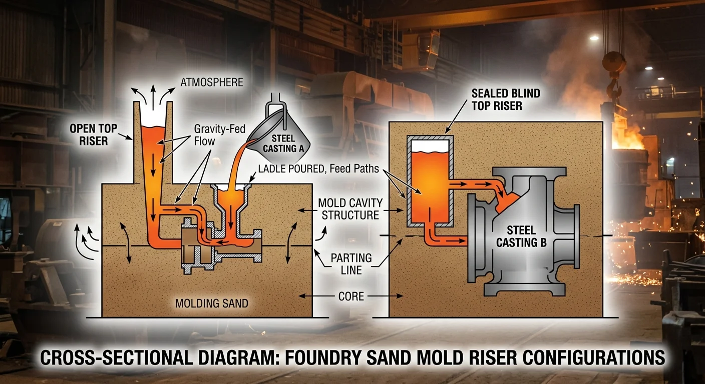
The top riser sits at the highest point of the mold. The casting shrinks. Molten metal flows down into the hot spot along the shortest feeding path. No pressure tricks. No complex geometry. Just a clean, uninterrupted channel from reservoir to void.
That simplicity is why top risers dominate large and heavy steel castings — machine tool bases, mining equipment frames, structural components. In these parts, a shrinkage cavity isn’t a cosmetic issue. It’s a structural failure waiting to happen.
The design rules are strict for a reason:
-
The riser must solidify after the casting section it feeds — no exceptions
-
The feeding channel must stay open all the way to the hot spot, with the expansion angle pointing back toward the riser
-
Control the height-to-diameter ratio — too tall, and the metal at the top cools too fast. The pressure head dies before the job is done
Shape matters too. Standard forms include cylindrical, spherical-top cylindrical, and oval cylindrical. Avoid spherical risers — they can’t hold enough metal head pressure to do the job.
Real numbers back this up. One documented optimization used a top riser with a volume of 387,074 mm³. It pushed liquid isolation time from 264 to 335 seconds on the middle flange and from 437 to 482 seconds on the side flanges. Yield jumped by 17.65% — a solid gain on any production run.
For steel, open top risers cover smaller castings. Bigger pours move to blind top risers. These use controlled atmosphere and thermal conditions to extend the feed window even further.
Side Riser: The Manufacturing Line’s Best Friend
Not every casting line runs horizontal. Vertical molding lines are the backbone of high-volume foundry production. They demand a riser that fits the process geometry — not the other way around.
That’s what the side riser delivers.
It sits on the side of the pattern plate, not on top of the casting. This lets it fit straight into vertical molding lines without adding mold height. That matters more than it sounds. Every extra millimeter of vertical clearance on a mechanized line creates a constraint — on throughput, on plate loading, on the whole operation’s rhythm.
What makes side risers work on vertical lines:
-
Telescopic placement — the Tele-Side-Feeder system mounts onto the pattern plate with no line redesign. Or insert sleeves drop in post-compaction through a core inserter. Both options are clean and simple.
-
Increased unit weights and plate loading — more casting mass per cycle, same footprint
-
Built-in venting — gas-induced defects get stopped before they form, not after
Blind side risers lead in industrial vertical molding for one key reason: heat retention. The enclosed shape keeps feed metal liquid longer than open-top forms. You need that extra liquid time for pump body housings or high-volume automotive parts. Yield percentage hits your cost per part fast — so keeping metal liquid longer pays off.
The result is a tighter, faster, cleaner process. Higher yields. No extra height. Fewer defects coming off the line.
Open Riser vs Blind Riser: How to Choose the Right Enclosure Type
The enclosure decision looks simple on paper. It isn’t.
Open risers expose their top surface to the atmosphere. You can see the metal level. You can add insulating powder or pour more metal in. That visual feedback is useful — more so on short runs, prototype work, or castings where shrinkage behavior is still being figured out. For small-to-medium steel pours and small non-ferrous castings at the highest mold points, open risers are a clean, low-complexity solution.
But exposure cuts both ways. Radiation and convection strip heat from the top surface without stopping. The metal freezes downward from that open face. Vacuum pockets form. Feeding stops too soon. Traditional open risers average ~15% efficiency because of this. That’s a lot of metal doing no useful work.
Blind risers fix the heat loss problem by sealing the top. No atmospheric exposure means the feed metal stays liquid longer. Add insulating sleeves or exothermic hot toppings — these trigger a heat reaction that keeps the liquid phase alive — and efficiency climbs to 30% or higher. Advanced blind mini-riser designs have been recorded at 70% efficiency ratings. That gap between 15% and 70% is not small. On high-volume production, it’s the difference between a profitable casting line and one that burns through metal yield.
The venting problem is real but solvable. Blind risers need an air path or they build back-pressure that chokes feeding. Venting chambers solve this — comparison studies show clear feeding improvement over unvented blind setups. Sleeves with hot toppings pull double duty: they keep the top surface molten and hold the air channel open at the same time.
Here’s how to make the call across three dimensions:
|
Dimension |
Open Riser |
Blind Riser |
|---|---|---|
|
Production Volume |
Small/medium batches |
High-volume production runs |
|
Alloy Type |
Steel (high shrinkage, gravity feed); small non-ferrous castings |
Gray/ductile iron; large steel; large non-ferrous |
|
Casting Complexity |
Simple geometry; accessible top positions |
Complex shapes; heavy sections; lower or hidden locations |
A quick note on placement: blind risers belong at heavy sections and lower positions where open access isn’t possible. Open risers belong at the highest points of the mold — gravity feeding works cleanly there, and you get real value from being able to monitor the pour. Shape follows function. Go cylindrical for easy removal. Use tapered or necked shapes for non-ferrous castings where cutting heat loss at the neck matters.
The choice isn’t philosophical. It’s geometric, thermal, and economic — and the numbers make the right answer clear.
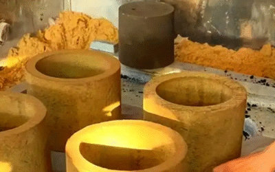
Cylindrical Riser: Why the Most Common Shape Is Still the Most Reliable
Foundries have tried fancier geometries. They keep coming back to the cylinder.
That’s not inertia. That’s evidence.
The cylindrical riser dominates for one reason: it controls the volume-to-surface-area ratio better than any other shape. That ratio stays consistent all the way around the circumference. No corners dump heat into the sand faster than the center. No flat edges push one side to solidify early while the other side stays liquid. The cylinder cools at the same rate across its entire surface — and that means feeding stays on schedule.
The geometry works in your favor at every step:
-
H/D ratio control — Adjust the height-to-diameter ratio to tune solidification time. You don’t have to redesign the whole riser system to make it work.
-
Modulus calculation is straightforward — Engineers can hit the required modulus targets with no geometric correction factors cluttering the math. The numbers are clean and direct.
-
Removal is clean — Cylindrical necks break at the right spot. Odd shapes don’t give you that kind of consistency.
It works across alloys. Steel, aluminum, ductile iron — the cylinder fits them all without extra adjustments. It suits top riser positions and blind configurations just as well. You can add insulating sleeves or exothermic treatments without touching the base design.
Every casting process has its go-to solutions. The cylindrical riser is one of them — not because no one has tried to replace it, but because the math keeps proving it right.
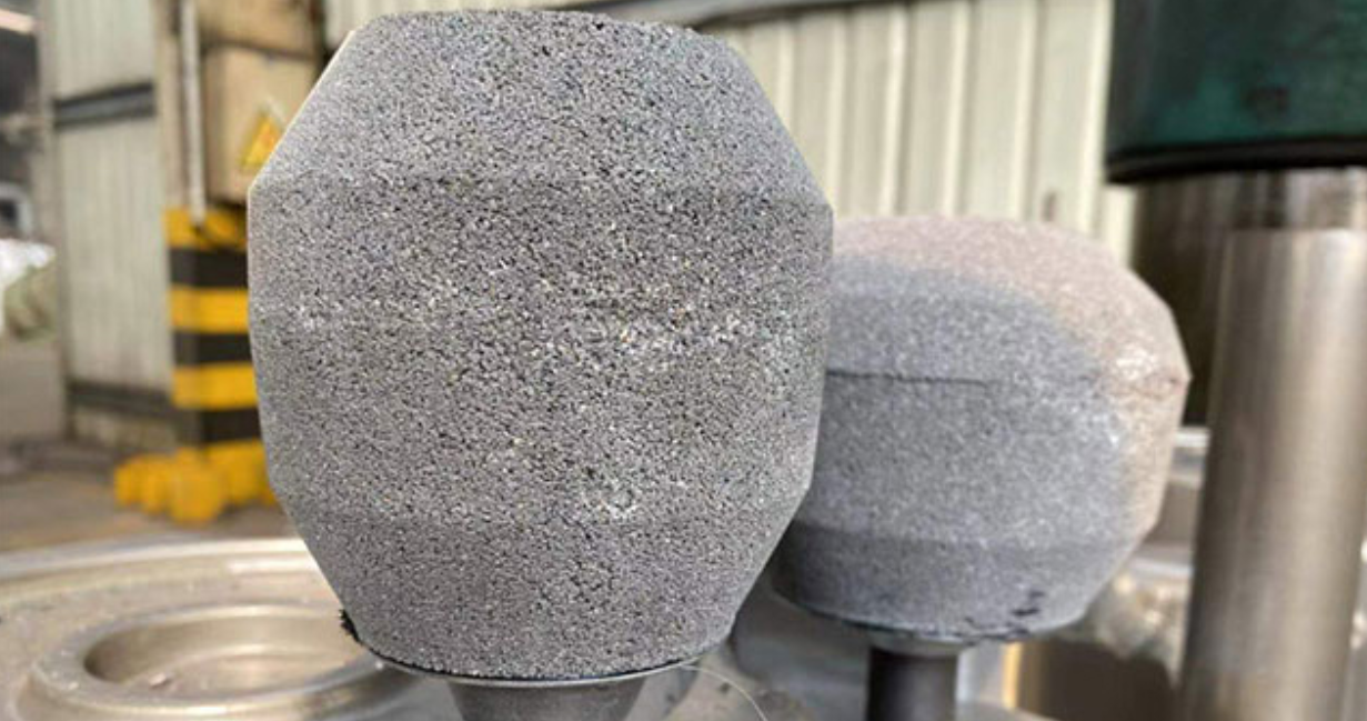
Spherical-Top Cylindrical Riser: Maximum Efficiency Under Pressure
Cut a conventional cylindrical riser in half by volume. You still get the same solidification time. That’s not a theoretical gain. That’s what the spherical-top cylindrical geometry delivers in real foundry conditions.
The math is simple. A spherical shape has a lower surface-area-to-volume ratio than a pure cylinder. Less exposed surface means slower heat loss. Slower heat loss keeps the feed metal liquid longer. That’s what high-shrinkage alloys like Al-12%Si need most.
The numbers hold up under testing:
-
50% volume reduction versus conventional cylindrical risers, with identical solidification time
-
26.5% casting efficiency gain — not incremental, structural
-
7% longer feeding window during solidification
-
47.27% reduction in entrained air volume fraction — a defect source most foundries underestimate
The trade-off is real. Spherical geometry makes mold construction harder. Sand-printing handles it well. Traditional mold-making does not. So adoption stays focused on batch-sensitive, high-shrinkage applications. Those are the cases where the efficiency gain is worth the extra effort.
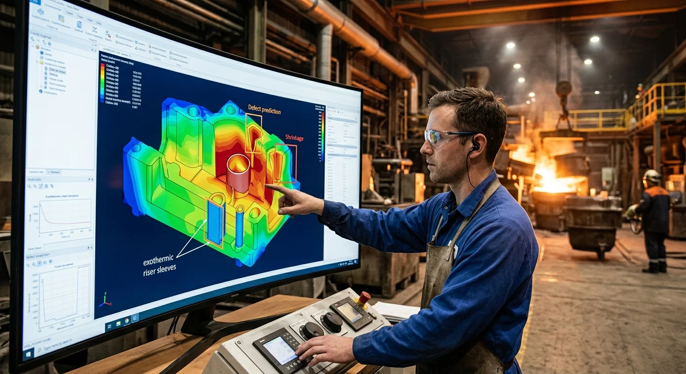
Design spec to hit: VR/Vc ratio of 0.35 for plate castings, with a shape factor (L+W)/T of 16. Freezing ratio must exceed 1.2 per Caine’s method. Run a simulation to confirm. ANSYS results show porosity shifting toward the riser, away from the part. That’s the geometry doing its job.
The numbers keep pointing to the same answer. For high-pressure, high-shrinkage work, the spherical-top cylindrical riser delivers the best efficiency on the table.
Oval Cylindrical & Annular Riser: Solving the Problem of Non-Round Hot Spots
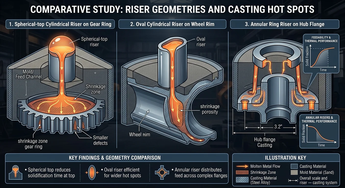
Some castings don’t shrink in circles. Gear rings, wheel rims, hub flanges — their hot spots stretch along an axis, or wrap around a radius. A round riser centered on that geometry feeds one point well and starves everything else.
That’s the problem oval cylindrical and annular risers exist to solve.
The oval cylindrical riser follows the hot spot’s footprint. A standard cylinder drops metal into one concentrated zone. The oval form spreads feeding across a longer, stretched section instead. The contact shape matches the actual shrinkage path. So the metal goes where the void is forming — not where a riser is easiest to place.
The annular riser works differently. It doesn’t sit above or beside the casting. It wraps around it. Cylindrical or sleeve-shaped parts — hubs, rings, pipe flanges — build heat around a full circumference. The annular riser matches that pattern. You get feeding across the entire ring, not just one side.
Why this matters in practice:
-
Round risers on non-round hot spots cause uneven shrinkage. Porosity builds up at the far ends of the feed zone, away from where the riser sits
-
Matching riser shape to hot spot shape cuts that concentration down. The feed reaches the right areas, not just the nearest ones
-
Modulus calculations for oval and annular risers are harder than standard cylindrical work. Simulation tools like MAGMASOFT are the go-to for checking these designs before the first pour
The shape of the shrinkage should drive the shape of the solution. That’s exactly why these two riser types exist.
Mini-Riser: The High-Pressure Molding Game Changer with 70% Feed Efficiency
Seventy-five percent feeding efficiency. Traditional open risers average 15%. That gap doesn’t just stand out — it changes the economics of the entire pour.
Two things drive that number. First, a ceramic-based exothermic matrix that pushes heat straight to where shrinkage forms. Second, a reduced neck diameter that cuts fettling costs without hurting feed performance. Less metal in the riser. More metal in the part. That’s the whole game.
What makes it work on high-pressure lines:
-
Compressive capacity exceeds 7 MPa — it holds up under peak pressure from automated molding machines without crumbling
-
Spring pin integration cuts contact area and pattern wear, and it fits any automated molding machine with no line redesign needed
-
Integrated riser cap stops loose particles from falling into the mold cavity during compaction
The ceramic matrix is what sets mini-risers apart from fiber sleeves. Fiber compresses under high-pressure ramming. Ceramic holds its shape. That difference is why the HD/XD mini-riser became the go-to solution for ductile iron axle castings — a tough application where both pressure tolerance and localized feeding matter.
You get full compatibility with resin sand and clay sand processes. The mini-riser also comes in fluorine-free, low-emission formulations. So it fits modern foundry environmental standards without giving up any performance.
Smaller volume. Higher exothermic energy density. Precision feeding where it counts.
Heated Riser (Exothermic Riser): The Solution for Complex Castings with High Shrinkage
The chemistry inside an exothermic riser sleeve looks simple — aluminum, sand, and an oxidizer, resin-bonded into a cylinder. Molten metal hits it, the aluminum oxidizes, and heat pushes straight into the feed reservoir. That reaction stretches solidification time by 50%. For complex castings with heavy sections and tight shrinkage windows, that extra time is the difference between a usable part and a scrapped one.
Here’s what the numbers look like in practice:
-
30–35% more heat retained versus unsleeved risers
-
Optimal sleeve thickness: 25 mm — go thinner and you’re leaving yield on the table. Most sleeves sold today are undersized.
-
At a riser modulus of 1.6 cm, the peak MEF value hits 1.90 with a 285-second solidification window
-
The global riser sleeve market hit $561.6 million in 2023 — exothermic sleeves hold over 45% of that market because the feeding efficiency gap isn’t even close
The automotive industry pulls 40% of total demand. Steel casting leads the highest revenue segment. That’s no accident. Steel shrinks hard. Complex geometries build feeding paths that standard risers can’t hold long enough. Exothermic sleeves fill that gap.
|
Exothermic |
Insulating |
|
|---|---|---|
|
Mechanism |
Chemical heat generation |
Passive heat retention |
|
Solidification extension |
~50% longer |
Moderate |
|
Market share |
45%+ |
Secondary |
How to Select the Right Riser Type: A Practical Decision Framework
Four variables determine every riser selection decision. Get them right, and you’re looking at a 95% defect-free success rate. Miss one, and you fall back to the 70% empirical baseline — scrapping parts and losing yield.
The variables are: alloy shrinkage rate × casting geometry complexity × production process × cost target. They interact, and they all matter.
Start with the alloy. Gray iron shrinks 1.0–1.5%. Ductile iron runs 1.2–1.8%. Steel pushes 2.0–3.0%. Higher shrinkage means more feed volume. That extra volume drives riser size up.
Then map the geometry. Simple castings with a low V/A ratio below 2.0 go to blind risers. Complex geometries above 4.0 need open or top risers with full feeding access.
Match the process. Manual molding tolerates larger necks — 20–30% of riser diameter. Mechanical lines tighten that to 10–20%. High-pressure molding drops it further to 5–10% extra volume. The neck diameter sweet spot is 0.2 × riser diameter. That’s where you hit 70% cost-flow efficiency without blocking the feed path.
The Five-Step Design Procedure
-
Calculate casting modulus — find the minimum V/A ratio
-
Set riser modulus at 1.2–1.5× casting modulus
-
Size the neck at 0.6–0.8× riser diameter
-
Confirm feed volume meets ≥1.1× shrinkage volume
-
Check that solidification time meets the Niyama criterion above 120°C/s
Push riser volume past 200% of casting modulus, and you’re adding a 15–25% cost penalty with zero feeding benefit. Stay in the 120–150% target zone.
Riser Efficiency Comparison Table: All 10 Types at a Glance
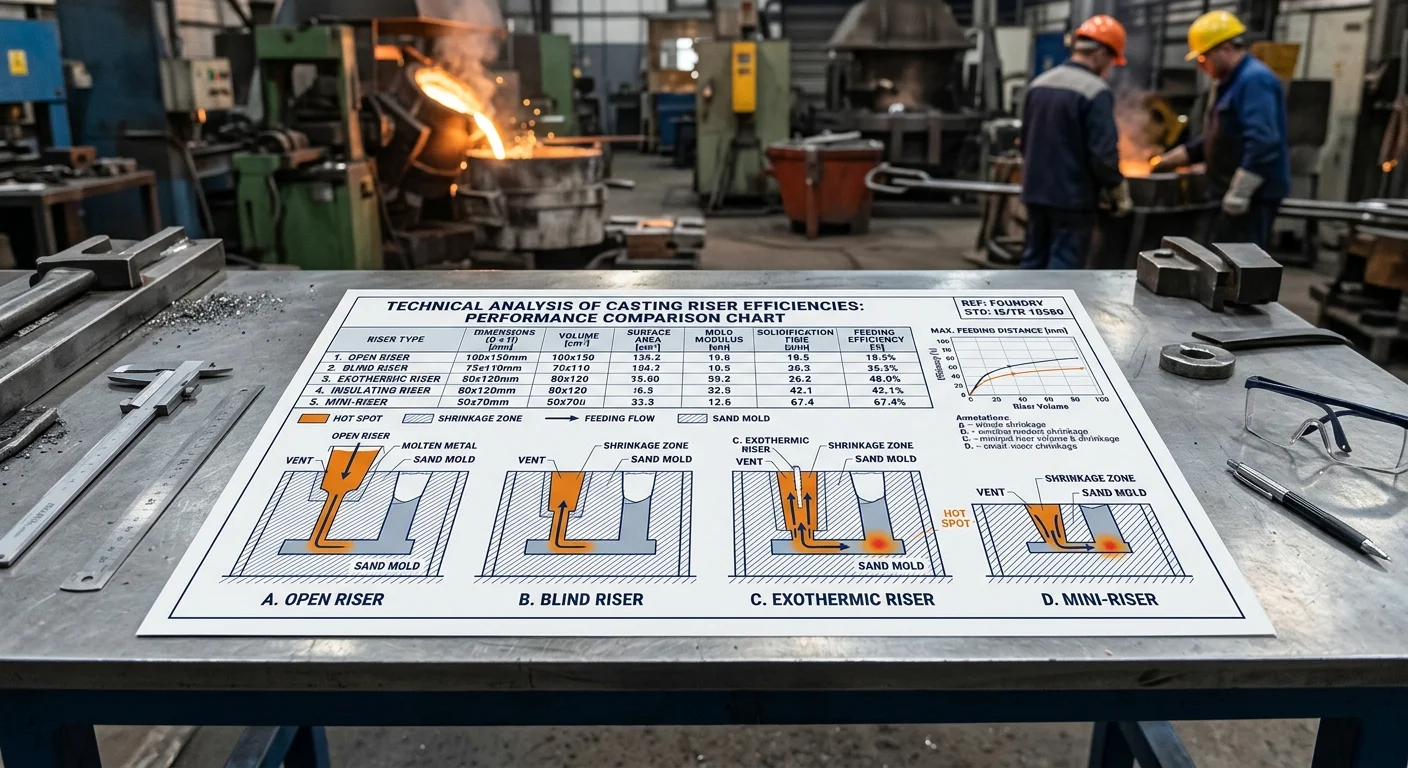
The numbers settle most arguments faster than theory does.
|
Type |
Efficiency |
Applicable Alloys |
Best For |
Trade-off |
|---|---|---|---|---|
|
Open Riser |
15% |
Gray Iron, Steel |
Simple sand castings |
Heat loss kills yield |
|
Side Riser |
18–22% |
Iron alloys |
Valves, vertical lines |
Uneven solidification risk |
|
Blind Riser |
20–25% |
Ductile Iron, Aluminum |
Engine blocks, housings |
Limited insulation |
|
Insulating Sleeve |
25–35% |
Gray/Ductile Iron |
Cylinder heads |
Thickness-dependent |
|
Top Riser + Hot Top |
28–32% |
Steel |
Ingots |
Oxidation exposure |
|
Blind + Exothermic Sleeve |
30% |
Steel, High-strength |
Heavy sections, wheels |
Sleeve cost |
|
Exothermic Sleeve (Thick) |
35–45% |
Steel |
Large castings >500kg |
Higher material consumption |
|
Pressurized Riser |
40–50% |
Aluminum |
Automotive parts |
Requires pressure equipment |
|
Hybrid (Blind + Mini) |
50–65% |
Mixed alloys |
Complex geometries |
Design complexity |
|
Mini-Riser |
70% |
Aluminum, Magnesium |
Thin-wall, high-pressure lines |
Precision sizing required |
The efficiency gap from bottom to top — 15% to 70% — isn’t marginal. It’s a production economics story told in yield percentages.
The upgrade path is linear:
– Open → Blind adds enclosure: +5–10%
– Add exothermic chemistry: another +5–8%
– Optimize to mini-riser geometry: jumps to 70%
Running small-batch manual operations? Open and blind risers hold costs down at 15–25% efficiency. No special equipment needed. Running high-volume automated lines? Mini-risers and exothermic sleeves push yield past 50%. That clears the >50% yield target that makes large runs profitable. One real steel casting case shows it clearly — optimized risering alone cut gating weight by 18%. Riser selection connects directly to cost reduction.
The table above maps every major type across the top 10 types and applications of risers in casting. Match your alloy, your geometry, and your production scale. The right efficiency tier falls into place from there.
Conclusion
Choosing the wrong riser doesn’t just waste metal. It scraps parts, burns time, and eats into your yield rates cast after cast.
The good news? You now have a complete map. From the gravity-fed reliability of a top riser to the thermal strength of an exothermic sleeve, each of the top 10 types and applications of risers in casting solves a specific problem in a specific situation. Match the riser to the hot spot. Match the geometry to the feed path. Get that decision right, and shrinkage porosity stops being a recurring nightmare. It becomes a solved problem.
Your next move is simple. Pull up your most troublesome casting design. Run it against the decision framework. Cross-reference the efficiency table. The answer is already there.
The best foundries don’t just pour metal well — they feed it better than everyone else. Now you know how.