Shrinkage doesn’t announce itself. It hides inside your casting until the part fails inspection — or worse, fails in the field.
Choosing between a top riser and a side riser in sand casting is a foundational call. It determines whether your part comes out sound or scrapped.
Get it right, and you’ve got clean, dense metal where it counts. Get it wrong, no amount of finishing work saves you.
This guide skips the theory and gets into the real mechanics of both feeding methods:
-
How each one works
-
Where each one performs best
-
How your part geometry and alloy should drive that choice
Top Riser in Sand Casting: How It Works and Where It Excels
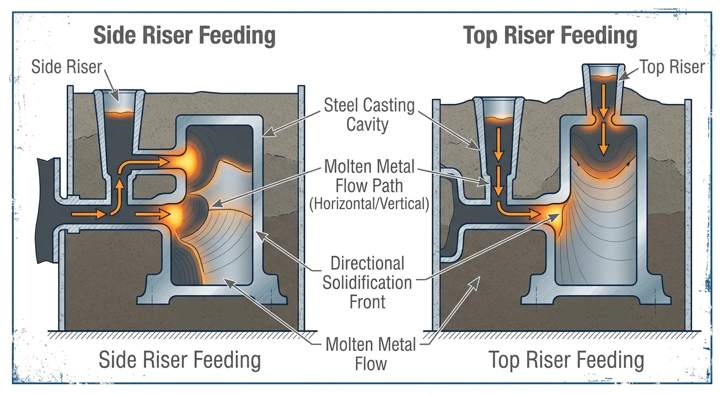
A top riser sits above the casting. That position is the whole game.
Liquid metal is heavy. Gravity pulls it down. Put a reservoir of molten metal at the top, and it feeds downward into the casting as solidification shrinks the volume. No pumps, no pressure systems. Just physics doing the work.
The riser has one non-negotiable job: stay liquid longer than the casting beneath it. That’s why the riser modulus must exceed the casting modulus by a factor of 1.1 to 1.2. Your casting modulus is 11.63 cm? Your riser bottom needs to land between 12.79 and 13.96 cm. Miss that window, and the riser freezes first. Feeding stops. Shrinkage forms right where you don’t want it.

Where Top Risers Perform Best
Top risers shine on large, thick-walled steel castings — the kind where heavy sections sit at the top and need a steady feed of metal through the full solidification cycle. Parts with a volume-to-surface-area ratio above 4.0 are a natural fit. The feed distance stays short. The footprint stays compact. You lose less material from your yield.
They also serve a second purpose: venting trapped gas and pulling in slag before it contaminates the casting.
Shape matters more than most engineers admit:
-
Spherical-top cylindrical — the workhorse. Strong V/A ratio, longer solidification time than the part below.
-
Annular (ring) riser — wraps around the hot spot on large, heavy components.
-
Necked top riser — common in steel casting; the neck controls heat influence and makes cutoff simpler.
The Real Limitations
Top risers take up space on the top face of the mold. That surface needs a clean finish or tight tolerance? The riser’s heat footprint becomes a problem. Residual heat near sidewalls can trigger shrinkage porosity and surface depressions. Angling the riser between 10° and 30° from vertical cuts that risk down.
Mechanized molding adds friction. Multiple core boxes, split patterns, and careful sand packing around the riser neck make top riser setups a poor match for high-volume automated lines.
And the cutoff? That metal goes back into the melt. Every top riser you remove is scrap that needs reprocessing — a cost that stacks up fast across a long production run.
Side Riser in Sand Casting: How It Works and Where It Fits
Position changes everything in riser design. Move the reservoir from the top of the mold to the side, and you’re dealing with a different set of physics — different fill sequence, different heat dynamics, different trade-offs.
A side riser sits next to the mold cavity, almost always in blind riser form. Here’s the key difference from a top riser: the cavity fills first through the gating system. The side riser fills last. That sequence matters. It means the side riser arrives full of hot metal right as the casting starts to shrink — ready to compensate, not sitting idle.
The Heat Problem You Have to Manage
The geometry creates a thermal disadvantage you can’t ignore. A side riser loses heat from four exposed surfaces. A top riser loses from three — the bottom stays insulated by pooled molten metal. That 25–33% increase in exposed surface area means the side riser solidifies faster. All else being equal, it’s working against you.
Three adjustments close that gap:
-
Raise pour temperature by 50–100°C to extend liquidity
-
Shorten fill time to under 10 seconds to keep the metal hot through the feeding window
-
Apply insulation coatings to slow surface heat loss and hold the feeding channel open longer
The neck geometry does critical work here. A hemispherical bottom profile delays neck solidification. It keeps the feed channel open longer than a flat or squared connection would. Keep the neck cross-section tight enough to simplify cutoff, but large enough that it doesn’t freeze before the casting does.
Where Side Risers Win
Three scenarios tilt hard in favor of side risers.
Mechanized and automated molding lines. Side placement fits well into mechanized setups. No complex core boxes, no split-pattern gymnastics. The riser drops into position consistently, cycle after cycle.
Live riser gating configurations. Metal routes through the riser before entering the cavity — the “hot riser” approach. The riser arrives at peak temperature. The result: you need 20–30% less riser volume compared to a dead, cold riser filled after the fact. That’s direct yield improvement on every pour.
Fast post-casting removal. Side placement lets you cut off in under five minutes with minimal grinding. On long production runs, that time adds up to real cost savings.
Sizing It Right: Chvorinov and Caine
The math still governs. Chvorinov’s Rule is clear: riser solidification time must exceed casting solidification time. Expressed as modulus — V_r/A_r must exceed V_c/A_c. For a cylindrical side riser, the sweet spot is a height-to-diameter ratio of 1.0 to 1.2. Go too far in either direction and you trade thermal efficiency for geometric convenience.
Caine’s method adds a second check. Plot your X = V_r/V_c against Y = A_r/A_c on the modulus curve. For steel, staying above X > 1.2 with Y < 0.8 keeps you in defect-free territory. These aren’t conservative rules of thumb — they’re the minimum thresholds that separate sound castings from expensive scrap.
One real limitation: side risers feed sideways rather than straight down through the casting cross-section. In thick sections with strong directional solidification fronts, that angular mismatch costs you 10–20% feeding efficiency compared to a top riser. Vertical casting lines can recover some of this loss through telescopic downward action. In heavy-section horizontal geometry, though, a top riser often still wins on pure feeding performance.
Top Riser vs Side Riser: Direct Comparison Across Key Decision Factors
Five factors separate a sound casting from a scrapped one. Riser position drives all of them.
Here’s the direct breakdown — no overlap with what’s already been covered on individual riser mechanics. Just the head-to-head numbers and decisions that matter at the design stage.
Space and Feeding Distance
Top risers win on footprint. They occupy less flask space and keep feeding distances short. That efficiency adds up across a production run — less material, tighter mold layouts, fewer complications.
Side risers need more room. Feed metal has to turn corners to reach every section of the casting. The path is longer. Thermal losses along that path are real. Complex geometries with multiple isolated thick sections may need more than one side riser to cover the distance. That eats into yield fast.
Pressure Dynamics
This is where alloy choice starts driving the decision.
Top risers carry a hydrostatic pressure advantage. The column of molten metal above the casting pushes feed metal down through thin sections under gravity load. For light metals like aluminum, that pressure assist is often the deciding factor. It lets feed metal reach section transitions that a side riser can’t cover with the same reliability.
Side risers don’t get that pressure for free. To feed properly from a side position, the riser has to sit at a height that makes up for the missing gravity load. That’s an extra design constraint. It adds complexity without adding performance.
Live vs. Dead Configuration
Top risers are almost always dead risers — cold by the time the cavity fills. The metal they hold has already passed through the system.
Side risers have options. A live riser gating setup routes hot metal through the riser before it enters the cavity. That metal arrives at peak temperature. It also needs 20–30% less volume to do the same job. That’s a real yield advantage. Top risers can’t match it by design.
Solidification Control
Top risers give you more predictable directional solidification. The feed path is short. Pressure stays consistent. Solidification sweeps cleanly downward from casting to riser. Your part needs tight control over where solidification fronts meet? That predictability pays off.
Side risers need careful placement. Solidification has to move from the outer edges of the casting inward toward the riser. Get the placement wrong and you trap shrinkage instead of feeding it out.
The Decision Matrix
|
Factor |
Top Riser |
Side Riser |
|---|---|---|
|
Flask space |
Less |
More |
|
Feeding distance |
Shorter |
Longer |
|
Pressure advantage |
Hydrostatic, built-in |
Requires height compensation |
|
Configuration |
Dead riser |
Live or dead |
|
Solidification control |
More predictable |
Placement-dependent |
|
Best alloy fit |
Aluminum, light metals |
Steel, heavy sections |
|
Yield efficiency |
Higher for simple geometries |
Higher with live riser gating |
Top riser is the right call for constrained space, light metal casting, and short feeding distances.
Side riser makes more sense for complex geometry, sections far from the top surface, or production lines running live riser gating to recover yield through temperature advantage.
Your part’s geometry tells you which column wins. Match the riser to the solidification path — not the other way around.
Riser Placement Principles: How to Position Either Type for Maximum Feeding Effectiveness
Placement isn’t an afterthought. It decides whether your riser feeds the casting — or just sits there while shrinkage forms beneath it.
The starting point is always the hot spot.
Find the Hot Spot First
Every casting has a section that solidifies last. That’s your hot spot. Find it, and you know where the riser needs to go.
The modulus method gives you the number: V/A ratio. The section with the highest V/A solidifies last. That’s where shrinkage forms if you don’t feed it head-on. Computer simulation can map this across complex geometries, but the modulus calculation is the foundation. Don’t skip it.
Once you’ve identified the hot spot, the placement rule is straightforward: get the riser as close to it as possible. Right above for a top riser. Side-by-side for a side riser. The further the riser sits from the hot zone, the less useful work it does.
Measure Your Feeding Distance — Then Enforce It
Feeding distance (FD) is the straight-line measure from the riser-casting junction to the farthest point that needs feed metal. Every riser has a limit. Push past it, and the far end of your section starves.
Real numbers: a section at C-C might accept a feeding distance of 12.2 inches. Section D-D at 10.8 inches already demands two risers. These aren’t soft guidelines — they’re the hard boundary of what physics allows.
Running multiple risers? Overlap their feeding circles. Coverage areas are additive. A gap between two feeding zones becomes a shrinkage zone.
Build the Path for Directional Solidification
Metal has to flow toward the riser, not away from it. Solidification must move from thin sections inward to thick sections. The riser sits at the thermal peak.
The feed channel should widen toward the riser — an expansion angle that keeps the path open. Flip that geometry and you create a freezing pinch point. The feed channel closes before the hot spot gets its metal.
For top risers: position at the highest, thickest point. Route the ingate below the riser so hot metal arrives there last.
For side risers: place adjacent to the hot spot with a hemispherical bottom at the junction. That profile slows neck solidification and keeps the feed channel open through the full feeding window.
Don’t Place Where It Creates New Problems
A riser leaves a mark. Plan where that mark lands.
Stay away from stress concentration areas and crack-prone geometry. Residual heat near a tight radius or a section transition can swap one defect for another.
Prioritize machining surfaces for riser placement wherever the part allows it. The cutoff scar gets cleaned up anyway. Placing the riser there removes a finishing problem rather than adding one.
Isolated thick sections at different heights need separate risers. One riser feeding across a height gap leaves the upper zone short on metal. Chills can help, but they don’t replace placement that matches the geometry.
The Sizing Baseline
Placement and sizing work together. A well-positioned riser that’s undersized still fails. Both have to be right.
The benchmarks:
– Riser volume: 1.5 to 2.0 times the volume of the section it’s feeding
– Riser diameter: must exceed the section thickness
– Riser modulus: must exceed the casting hot spot modulus — Chvorinov’s relationship confirms that solidification time scales with modulus squared
Nail both — position and size — and the feeding path works as intended. Get one wrong, and you’re chasing a shrinkage problem that already had a clear answer.
How Part Geometry and Alloy Type Should Drive Your Riser Choice
Two variables override everything else in riser selection: part shape and pour metal. Get both right, and your riser placement decisions from the previous sections fall into place. Miss either one, and you’re working against yourself.
The Modulus Ratio Is Your Starting Point
The V/A ratio — volume divided by surface area — tells you which riser type belongs on your part.
Low V/A below 2.0 mm means thin sections, fast heat loss, and rapid solidification. That geometry needs blind risers — side or top blind — placed to feed isolated pockets before they freeze out. Open risers on thin-section parts lose their thermal advantage too early. They don’t finish the job.
High V/A above 4.0 mm means thick, heavy sections with long solidification windows. That’s the territory for open top risers. Size the neck to isolate shrinkage and hold the feed channel open through the full cycle.
The sizing math is exact — not a rough estimate. Take an aluminum casting: 100 × 50 × 20 mm volume, 16,000 mm² of surface area. Casting modulus lands at 6.25 mm. Target riser modulus: 1.3 × 6.25 = 8.125 mm. For a cylindrical riser with height equal to diameter, that puts you at 30 mm diameter, 30 mm height. There’s no judgment call in that number. It either meets the threshold or it doesn’t.
Alloy Shrinkage Behavior Changes the Multiplier — By a Lot
The riser volume multiplier isn’t a fixed number. It shifts with the alloy. Here’s how it breaks down across three common casting materials:
|
Alloy |
Thin Sections |
Moderate Sections |
Thick Sections |
|---|---|---|---|
|
Aluminum |
1.1–1.3× |
1.2–1.5× |
1.5–2.0× |
|
Grey Iron |
1.3–1.6× |
1.5–2.0× |
2.0–2.8× |
|
Steel |
1.4–1.8× |
1.8–2.5× |
2.5–3.5× |
These ranges don’t overlap. Each one reflects actual shrinkage behavior for that metal.
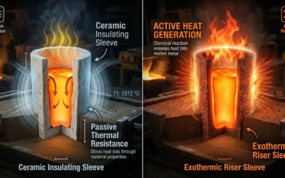
Steel shrinks 3–5% in linear terms and freezes across a wide temperature range. That means large top risers with insulating sleeves and tight directional solidification control. On heavy sections, the solidification front travels a long distance — so the riser has to stay active the whole time.
Grey iron breaks most of the standard rules. Graphite expansion during solidification offsets most of the volumetric contraction. Net shrinkage ends up around 1%. Smaller risers work fine. Blind risers cover thin to moderate sections. The feeding battle is far easier than it is with steel.
Aluminum sits in the middle. High thermal conductivity and a narrow freezing range make feeding straightforward on simple geometries. Push into thick or complex sections, though, and interdendritic shrinkage becomes a real risk. The multiplier climbs to 1.5–2.0× at that point. The riser design has to match it.
Complex Geometry Requires a Hybrid Approach
One riser can’t solve a multi-hotspot casting. It breaks down fast. A part with a thick central core and isolated thin projections needs two solutions: a top riser for the heavy core and blind side risers for the isolated sections. Neither type handles the full geometry on its own.
Chills are part of this too. Place them at thin-thick junctions and they break the shrinkage zones apart — turning one large feeding problem into two smaller, manageable ones. In steel and grey iron, smart chill placement cuts the required riser size by 20–30%. That’s a real yield improvement. Plus, it comes without adding riser volume or flask complexity.
Once you’ve mapped the geometry and alloy together, the selection becomes straightforward:
-
Thin geometry + aluminum or grey iron → blind or submerged risers at 1.1–1.6× multiplier
-
Thick geometry + steel → open top risers at 2.5–3.5×, with exothermic sleeves if the section demands it
Your part already has the answer. The geometry shows you where the hot spots are. The alloy tells you how much metal you need to feed them. Put those two inputs together, and the riser type — top or side, open or blind — becomes a clear, logical conclusion rather than a design guess.
Practical Decision Guide: Which Riser Type Is Right for Your Specific Part?
Four variables settle the question. Everything else is noise.
Casting material. Geometry complexity. Molding method. Surface requirements. Run your part through those four filters. The right riser type becomes clear — not a judgment call, not a gut feeling. A logical conclusion.
Here’s how each variable breaks down:
|
Dimension |
Top Riser |
Side Riser |
|---|---|---|
|
Casting Material |
Steel, high shrinkage >2% |
Aluminum, low shrinkage <1% |
|
Geometry |
Simple, thick sections >50mm |
Complex, thin walls <20mm |
|
Molding Method |
Sand/manual — top access easy |
Automated — side placement efficient |
|
Surface Requirements |
Top surface can absorb riser marks |
Top surface is critical, no marks allowed |
What Real Parts Look Like Against This Framework
A large steel valve body — 200 to 500 kg, 2.5% shrinkage — goes straight to a top riser at a 1.2:1 feeder-to-casting neck volume ratio. No debate.
Automated aluminum pipe fittings in the 10–50 kg range, with cycle times under two minutes, run side risers. The result: drag fin defects drop 15%. Side placement fits the line. Top placement doesn’t.
Automotive cylinder heads have complex geometry. Hot spots sit scattered across the part. Blind side risers handle this well. Yield climbs 8%. One riser placed in the right spot does what a badly placed top riser cannot.
The Errors That Cost You
Getting this wrong isn’t a theoretical problem. It shows up on the invoice.
|
Error |
Defect Rate Impact |
Cost Consequence |
|---|---|---|
|
Top riser without heat analysis |
Shrinkage porosity +25% |
$500–$2,000/part, 10% scrap rate |
|
Undersized side riser on thick sections |
Centerline shrinkage 30% |
Yield loss 12–18% |
|
No modulus matching |
Misrun rate +20% |
$10,000 batch failure |
Defaulting to a top riser because that’s what the last job used — that’s where most shrinkage problems start. The part changed. The riser decision didn’t.
Before You Sign Off With Your Supplier
Procuring rather than designing? These seven checkpoints separate a solid riser spec from a costly assumption:
-
Feeder modulus ≥ 1.2× the isolated modulus of the critical section (2.5 cm³/cm for steel)
-
Volume calculation: riser volume ≥ 1.5–2× the shrinkage volume — for steel at 2.5% shrinkage, build in at least 5% total
-
Neck insulation: ceramic fiber holds feeding yield at 92% — open neck drops to 65%
-
Simulation proof: ask for a Magmasoft or ProCast hot spot map. It should show riser solidification trailing the casting
-
Placement tolerance: neck length under 1.5× section thickness, chill distances confirmed
-
Trial data: X-ray or UT on three prototypes, porosity below 2% by volume
-
Cost transparency: riser material should land at 5–8% of total part cost; labor impact under 3% of cycle time
Any supplier who can’t produce numbers four and six isn’t running a process — they’re running a guess. Your part deserves better than that.
Conclusion
Choosing between a top riser and a side riser isn’t a coin flip. It’s an engineering decision that shapes whether your casting comes out sound or gets scrapped.
Part geometry drives the call. Tall, vertical sections need top risers. Flat, horizontal profiles with isolated hot spots need side risers. Factor in your alloy’s shrinkage behavior and solidification range. The right choice becomes clear from there.
Get the riser type wrong, and no finishing work fixes a shrinkage cavity buried in a critical wall. None.
Designing a new pattern or troubleshooting a defect? Take the decision framework from this guide and map it against your part geometry before your next pour. A first-run success or a costly rework cycle often comes down to one placement decision made at the start.
Make that decision with care.