Scrap rates don’t lie. Porous castings, shrinkage, inclusions — these point to a process that’s breaking down. Fixing one variable at a time won’t solve it. The real breakthrough comes from understanding how ceramic filters and risers work together to fix defect casting at a system level.
Filters aren’t just sieves. Risers aren’t just reservoirs. Each one does something the other can’t. Pair them right, and you’re hitting defects from two directions at once.
Stop guessing. Start making parts that pass inspection the first time.
What Causes Casting Defects in the First Place (And Why Single Solutions Fail)
Every defect has a story — and most of them start long before metal hits the mold.
Casting failures cluster around four core problems. Each one has its own root in metal flow or solidification physics:
-
Shrinkage porosity — Uneven wall thickness, poor gating design, or temperature swings cause metal to contract at different rates as it cools. The void left behind isn’t a mystery. It’s geometry and thermodynamics doing their job.
-
Slag inclusions — High pour rates and weak core strength let turbulent metal scrub the mold surface. Sand grains tear away. Oxide debris drags into the part. You often don’t spot it until machining.
-
Gas entrapment — Blind gating areas trap air. Moisture in tools or the melt releases hydrogen. Steam from cracked lines sneaks in. The metal looks solid. The porosity tells a different story.
-
Cold shuts — Metal cools before it fills. Low fluidity, cold dies, dirty metal — any one of these can cause two flow fronts to meet without fusing together.
Why Fixing One Thing Breaks Another
Here’s where most operations lose money. They isolate a defect, throw a targeted fix at it, and create a new problem downstream.
Drop your pour temperature to stop cold shuts? Shrinkage gets worse. Add venting without filtration? You’re pulling slag straight through. Optimize gating for laminar flow? Hydrogen porosity from the melt stays untouched.
A riser alone feeds volumetric shrinkage. It does nothing for gas entrapment or inclusions introduced during flow. A filter alone cleans the melt and calms turbulence. It can’t make up for metal contraction during solidification. Neither one covers all three defect categories — filling-related, shrinkage, and thermal.
The gaps aren’t random. They’re built into the process. That’s why understanding how Ceramic filters and risers work together to fix defect casting isn’t optional — it’s the one way to close all three at once.
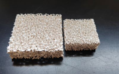
How Ceramic Filters Work: Filtration Mechanisms Beyond Simple Straining
Most people picture a ceramic filter as a fancy sieve. That mental model leads to more defects.
The reality is more interesting — and more useful. A ceramic filter doesn’t just block particles. It attacks contamination through multiple independent mechanisms. Each one targets a different threat to metal quality.
Here’s what happens inside the filter body:
The Four Mechanisms Working in Parallel
1. Mechanical blocking — The first line of defense. Pores sized at 0.5 microns catch solid inclusions, oxide films, and debris. Without this, those particles ride straight into the cavity. Size alone doesn’t get anything through.
2. Depth capture along winding paths — Particles that squeeze past the entry pores don’t travel in straight lines. The internal maze forces repeated direction changes. Smaller contaminants hit the pore walls and stick. The longer the path, the more gets captured.
3. Adsorption on ceramic surfaces — The filter wall does active work. Clay-based ceramics bind specific contaminants through a chemical bond — pulling them out of the melt, not just blocking their path.
4. Turbulence damping — Metal enters the filter fast and exits slow. The pressure drop across the filter body breaks up turbulent flow. This cuts the mechanical energy that tears at mold walls and creates new inclusions further down the line.
Why This Matters for Defect Control
Each mechanism handles a different particle size and type. No single one catches everything. Together, they build a multi-stage cleaning process — packed into just a few centimeters of ceramic structure.
That’s why ceramic filters fix defect casting problems that gating geometry alone can’t solve. The contamination is already in the melt before the runner system ever sees it.
How Risers Work: Feeding Molten Metal Through the Solidification Window
Solidification doesn’t happen all at once. It moves — creeping inward from thin walls and cool surfaces toward the last hot mass in the casting. That progression creates a window. Miss it, and shrinkage voids form. Hit it right, and the riser feeds them away before they ever become a defect.
Here’s the physics: metal contracts 3–7% by volume as it shifts from liquid to solid. That volume gap has to come from somewhere. A riser fills it. It’s a pressurized reservoir of molten metal sitting above or beside the casting. Atmospheric pressure pushes it down through the solidification front. It fills voids as fast as they open.
Timing Is Everything
The riser must outlast the casting section it feeds. The riser freezes first? The feeding channel cuts off mid-contraction. The rule is straightforward: riser modulus (V/A) must exceed the hot spot modulus of the section being fed. Solidification moves inward from the thin outer edges. The riser stays liquid the longest. It acts as the final heat anchor — the last zone to freeze.
Placement and Type
-
Top risers use gravity as a direct force. Best for large steel castings where you need maximum head pressure and slag flotation.
-
Side risers sit next to the fed section — practical for mechanized molding lines.
-
blind risers beat open ones on efficiency. Open designs do have one edge: they allow topping and exothermic treatment.
Steel puts the highest demand on risers. High shrinkage rates call for large, steady-feeding reservoirs placed at the last-to-cool position. You also need the shortest, most direct channel to the hottest section — any extra distance means slower feeding and higher void risk.
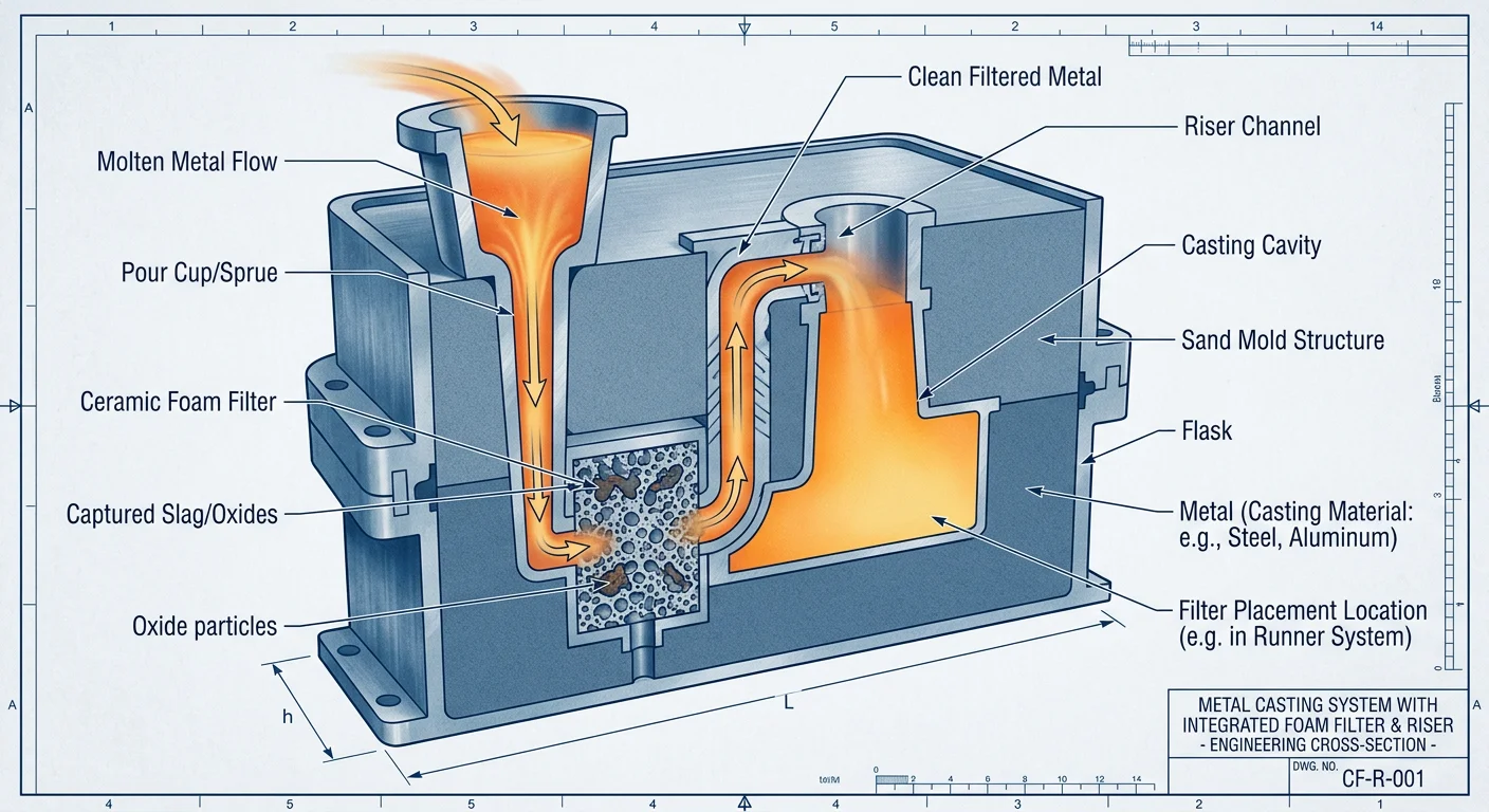
The Combined System: How Ceramic Filters and Risers Work Together Step by Step
Place the filter. Pour the metal. Watch physics do the rest.
That’s the clean reality of a well-designed ceramic filter and riser system. Understanding how it works is what separates foundries that keep guessing from those that get it right the first time.
How the Setup Works
The ceramic filter sits on a filter receptacle — a pre-molded support surface built into the riser seat. This isn’t a loose fit. Diameter matching is exact. A conical riser gets a conical filter. An oval riser gets an oval filter.
The geometry matters. Any gap between the filter edge and the riser wall is an unfiltered bypass. Bypasses erase everything you’re trying to accomplish.
No clamps. No adhesives. No float aids. The filter holds position through density difference alone. Ceramic is lighter than molten metal. So once the pour begins, physics takes over on its own.
The Step-by-Step Sequence During Pouring
Here’s what happens from first pour to filled cavity:
-
Metal enters the sprue/riser system — turbulent, fast, carrying whatever contamination survived the ladle.
-
The filter calms it — pressure drops across the ceramic body, breaking up chaotic flow before it can scrub the mold wall.
-
Metal level rises — the filter rises with it, floating upward on the density difference, keeping full cross-sectional coverage at every stage.
-
Filtration runs the entire pour — not as a single-pass gate at entry, but as an active, moving boundary between dirty incoming metal and the clean feed path above.
-
Clean metal reaches the casting cavity via the filtered riser channel — calmer, cleaner, ready to solidify without the load of inclusions that started the journey.
Why Full Metal Head Is Non-Negotiable
Drop the metal level below the filter mid-pour and two things happen fast. The filter loses its support and risks cracking under its own weight. The exposed riser wall opens an unfiltered path — and contaminated metal flows straight through.
Constant head pressure above the filter isn’t a preference. It’s structural. The system needs the filter to stay submerged and covered throughout the entire pour. No exceptions.
Get that right, and the results follow. Process reliability climbs. Riser efficiency improves. The expensive iteration cycle — pour, inspect, scrap, repeat — stops.
Defect-by-Defect: How the Combined System Fixes Each Problem
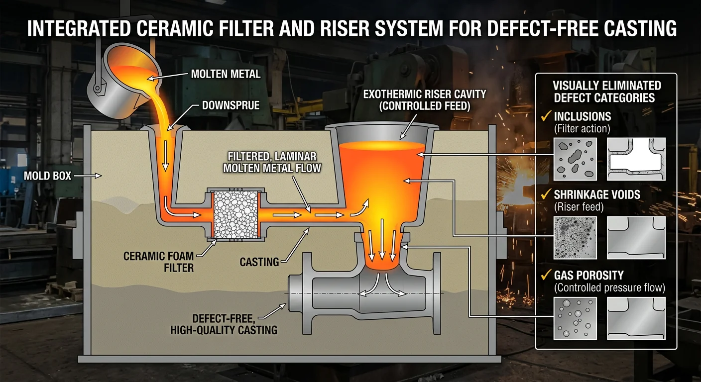
Three defect categories. Three failure modes. One integrated system that attacks all of them at once.
Ceramic filters and risers work together — each defect has a specific mechanical story, and the combined system has a specific answer for each one.
Slag & Oxide Inclusions: Two Capture Mechanisms, One Clean Stream
Slag doesn’t arrive in one size. That’s why a single filtration strategy always falls short.
Coarse slag and refractory debris get caught at the filter surface. Pores smaller than the particle block them outright. Fine oxides and magnesium silicates work differently — they don’t get blocked at the surface. Instead, they get trapped inside the ceramic foam structure. As metal winds through the internal path, adhesion and impaction pull those fine particles out of the stream.
Get the mesh sizing wrong in either direction and you’ve already lost:
– Too large, and slag rides through to the cavity.
– Too small, and metal backs up — insufficient flow, incomplete fills, a whole new class of defect.
Shrinkage Porosity: Why Inclusions Are the Hidden Culprit
A right-sized riser can still fail to prevent shrinkage. Most people never hear the reason why.
Non-metallic inclusions clog the interdendritic channels during final solidification. These narrow mushy-zone pathways carry liquid metal from the riser to contracting zones. Block them, and the riser’s reservoir becomes useless — clean metal can’t reach where it needs to go.
So filter first. Pull those inclusions out before the metal reaches the cavity. Those pathways stay open. The riser’s clean metal supply can do the job it was designed for.
There’s one more connection worth knowing. Inclusions act as nucleation sites for hydrogen bubbles. Remove the inclusions, and you cut gas porosity too — two defects solved by a single action upstream.
A quick visual guide to tell them apart:
– Shrinkage voids — jagged, angular, sponge-like
– Gas porosity — smooth, round, shiny
Different problems. The filter-riser system closes both.
Turbulence & Gas Entrapment: Flow Control as Defect Prevention
Turbulence doesn’t just carry inclusions. It creates new ones inside the gating system itself.
No tapered sprue means trouble. A cross-section that reduces 10–15% from top to bottom keeps metal pressed against the sprue walls. Without that taper, metal pulls away mid-pour. A vacuum forms. Air gets drawn in. Dross-forming conditions build up inside the very system you designed to stop them.
The filter calms that incoming stream. It breaks turbulent energy before metal hits the mold wall. Position it close to the casting gate, and you get maximum laminar flow right at the point of entry. Pair that with a sprue well sized at 2× the sprue base diameter in height — that geometry absorbs kinetic energy and smooths the vertical-to-horizontal transition.
The filter doesn’t just clean the metal. It changes how the metal moves:
– Less air entrapment
– Fewer new oxide films
– A mold cavity that fills at a controlled rate, not a chaotic one
Poor gating geometry creates inclusions on its own. The filter can’t make up for a chaotic system. Both pieces have to work together — flow control sets the conditions, filtration handles what’s left.
Placement and Installation: Where You Put the Filter Changes Everything
Location isn’t a detail. It’s the decision that determines whether everything else works.
Put a ceramic filter in the wrong spot and filtration completeness drops by 30%. Half your inclusion problem stays untouched. Same filter. Wrong spot. Different outcome entirely.
The Three Positions — and What You Give Up with Each
Every placement trades filtration completeness against flow rate. There’s no free lunch here.
Filter in the sprue — Maximum coverage: 95–100% filtration completeness. The cost is real. Flow rate drops 20–30% because metal hits the filter at full velocity. For high-inclusion-risk pours, that trade-off is usually worth it.
Filter in the runner — The middle path. You get 85–95% completeness with just a 10–15% flow penalty. Most well-balanced systems land here.
Filter in the riser seat — Flow disruption stays under 5%. The downside: completeness falls to 70–85%. Size the riser too large relative to the filter, and coverage gaps open fast. Easy to install. Not forgiving of sizing errors.
Sizing Rules That Don’t Bend
Match filter diameter to 80–90% of the riser’s inner diameter. That range isn’t random — it sits between two failure modes:
|
Mismatch Type |
What Happens |
Real Cost |
|---|---|---|
|
Undersized (>20% smaller) |
Channeling, bypass flow |
30–50% of metal unfiltered |
|
Oversized (>10% larger) |
Premature clogging |
Fails in 5–10 pours; 25% flow drop |
|
Poor edge alignment |
Gap formation |
15–25% contaminant bypass |
Bad sizing alone pushes inclusion defects up by 40%. The filter does its job. The geometry lets the defects go around it.
Pouring Technique: The Installation Step People Skip
The filter is set. The mold is ready. Then the pour goes wrong and the numbers collapse.
-
Keep stream velocity at 2–3 m/s. Go above that and turbulence creates new inclusions inside the Gating System
-
Position the ladle spout 100–150mm above the filter. Drop lower and you hit 40% flow restriction from direct impingement
-
Preheat mold and filter to 200–250°C for 30–60 minutes before the pour. Fall below 150°C and thermal shock cracking rates climb 20–30%
-
Hold a minimum 4-inch duct-to-filter gap. This cuts entry velocity by 50%, spreads flow across the full filter face, and doubles service life
Follow these specs and you get 40% higher contaminant removal plus 30% energy savings over unverified setups. Get the placement wrong — bad orientation, loose seals, no preheating — and filter lifespan drops 20–50%. Bypass channels open up and the entire system fails before solidification even starts.
The filter doesn’t decide its own effectiveness. You do. Placement is where that decision gets made.

Choosing the Right Ceramic Filter for Your Casting Application
The wrong filter doesn’t fail with a bang. It fails in silence — letting just enough contamination through to keep your scrap rate stuck high while you chase every other variable in the process.
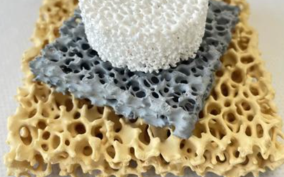
Material comes first. The alloy you’re pouring sets the ceramic chemistry. That chemistry decides whether the filter holds up through the pour or falls apart.
-
Aluminum alloys (up to 1000°C) → Alumina (Al₂O₃). Targets oxide films and dross.
-
Cast iron and copper alloys → silicon carbide (SiC). Built for higher temperatures. Handles slag and sand without issue.
-
Steel and high-temp alloys (up to 1700°C) → Zirconia (ZrO₂). This is the one material with enough thermal stability to stay intact and functional at those extremes.
Get that match wrong and the filter breaks down mid-pour. At that point, you’re not filtering anymore — you’re adding fragments.
PPI: The Trade-Off Nobody Talks About Enough
Higher pores-per-inch means finer capture. It also means more flow resistance. These two things are tied together. You can’t get one without the other.
10–20 PPI is the practical range for most Investment casting work. It balances filtration quality against metal flow. You won’t need to go way up on filter area to make it work.
Need finer PPI to catch aggressive fine inclusions? Compensate by increasing filter area — not by accepting the flow restriction. Misruns from underfilling are just a different defect. You’d be swapping one problem for another.
Sizing: The Ratio That Prevents Late-Pour Pressure Drop
Filter area relative to throttling area controls how much the filter slows your pour time. The numbers are clear:
|
Filter Area / Throttling Area Ratio |
Effect on Pour Time |
Verdict |
|---|---|---|
|
Less than 4 |
Much longer |
Avoid |
|
4–8 |
Slight increase |
Minimum standard |
|
Greater than 8 |
Negligible |
Target this |
Go a bit larger than your calculated minimum. Late in the pour, the filter loads up with captured material. A slightly oversized filter keeps pressure stable and prevents incomplete fills at the final sections of the cavity.
When Standard Foam Filters Stop Being Enough
Most operations run ceramic foam and never look back. That’s the right call — until it stops being one.
Three conditions point to precision 3D-printed filters:
-
Persistent high defect rates despite correct PPI selection — standard foam has inconsistent pore geometry, so contaminants slip through at irregular points
-
High-volume runs where foam filters load up too soon and push up late-pour pressure drop across production batches
-
Chemically aggressive melts where uniform porosity is what separates catching fine inclusions from letting them pass through
Custom 3D-printed filters improve flow paths and cleanliness for specific mold shapes and alloy combinations. Yes, the cost is higher. The yield improvement is real too — run controlled trials to validate both before scaling up.
How to Select Without Guessing
One variable at a time. That’s the only trial approach worth using.
-
Identify the specific defect: oxides, dross, sand inclusions, or fine particles
-
Select material based on alloy and pour temperature
-
Start at 10–20 PPI; size the filter area for a ratio above 8
-
Preheat mold and filter to 200–250°C — thermal shock cracking is an installation failure, not a material failure
-
Run the trial, measure scrap rate, change one thing
The filter that works is the one sized for your actual flow rate, matched to your alloy chemistry, and placed into a system where everything upstream is already under control. Filters don’t fix broken gating or bad melt practice. They close the gap that’s left after everything else is already right.
Common Mistakes That Undermine the Filter-Riser System
A filter-riser system can be specified right and still fail. The ceramic is correct. The riser fits. The metal still comes out dirty. These are the spots where things go wrong.
Letting the metal level drop below the filter is the fastest way to ruin your setup. The exposed riser wall turns into an open bypass. Air enters. Porosity follows. Rejection rates climb 20–30% from this one error alone.
Wrong filter diameter causes problems in both directions. Undersized filters choke flow and cause incomplete fills. Oversized filters let 15–25% more inclusions slip through the gap between the filter edge and riser wall. Neither outcome works.
Skipping preheat looks like a shortcut. It’s a thermal shock problem. Filter failure rates exceed 40% without preheating to 200–400°C. Cracked ceramic blocks melt flow. Misruns follow at a 10–15% scrap rate.
Improper seat depth opens leakage channels. Go shallower than 5mm and the filter shifts mid-pour, creating a 20% bypass. Go deeper than 15mm and slag traps too early — feeding stops before solidification finishes.
Defects Still Showing Up After Correct Installation?
Check these four variables in order:
-
Differential pressure across the filter: Above 0.5 bar signals clogging. A 20–30% flow drop confirms it.
-
Pore size mismatch: Too large (above 50μm) passes 15% of contaminants. Too small cuts flow by 40% and causes underfills.
-
Inlet/outlet reversal: Backflow cuts 30% of filtration efficiency. Check piping direction before every pour.
-
Material compatibility: Chemical leaching from mismatched ceramic adds 5–10% impurities into the melt — contamination coming from inside the system you built to stop contamination.
Fix the installation first. Then work through the variables. Most persistent defects after a filter-riser upgrade trace back to one of these six points — not to the filter spec itself.
Conclusion
Casting defects don’t survive a well-engineered system — they surrender to one.
Ceramic filters and risers do different jobs. But they solve the same problem. Filters pull out turbulence and inclusions before they settle in. Risers keep feeding the solidification front before shrinkage can take hold. One tool alone won’t close the gap. Together, they cover every stage where defects form.
The gap between a scrap pile and a clean casting comes down to three things: placement, pore size selection, and knowing why the metal is behaving the way it is. This guide has taken you through all of it.
So here’s your next move: audit your current setup.
-
Where is your filter sitting?
-
Does your riser volume match your solidification rate?
Ask those questions before your next pour — not after it.
Defect-free casting isn’t luck. It’s a system you build on purpose, one decision at a time.