Scrapping a casting run due to trapped slag or oxide inclusions hits hard. You lose material, time, trust, and margin — all at once. The right high-temperature filters for casting stop that from happening. Yet too many foundry operators are still guessing at filter selection, or just grabbing whatever’s cheapest on the shelf.
ceramic foam, honeycomb, Fiberglass mesh — each filter type has conditions where it performs best. Each also has conditions where it lets you down. Knowing the difference matters.
This guide gives you a direct comparison of the leading filter types across real casting conditions. You’ll also get a clear framework for matching the right filter to your specific metal, temperature range, and flow requirements.
Content Framework: “High-Temperature Filters For Casting: Which Works Best?”
Four filter materials dominate real foundry practice. Each covers a specific temperature range — go outside that range, and it costs you.
Here’s what this guide covers:
-
Temperature benchmarks by alloy — pouring ranges for aluminum, copper alloys, iron, and steel, matched against filter material limits
-
Filter-by-filter breakdown — SiC ceramic foam, zirconia foam, and carbon–alumina foam. You get specific products, real pore size ranges, cost differences, and where each one fails
-
A four-step selection framework — alloy temperature → pore size → filter sizing by casting weight → chemical interaction risk
-
Measurable performance data — industry benchmarks on inclusion reduction (30–70%) and scrap rate improvements (20–50%) from choosing the right filter
-
A quick-reference cheat sheet — one clear material recommendation per alloy group
Every section is practical. No theory without a real use case.
What Are High-Temperature Filters for Casting (And Why Filter Selection Matters)
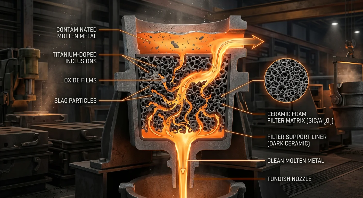
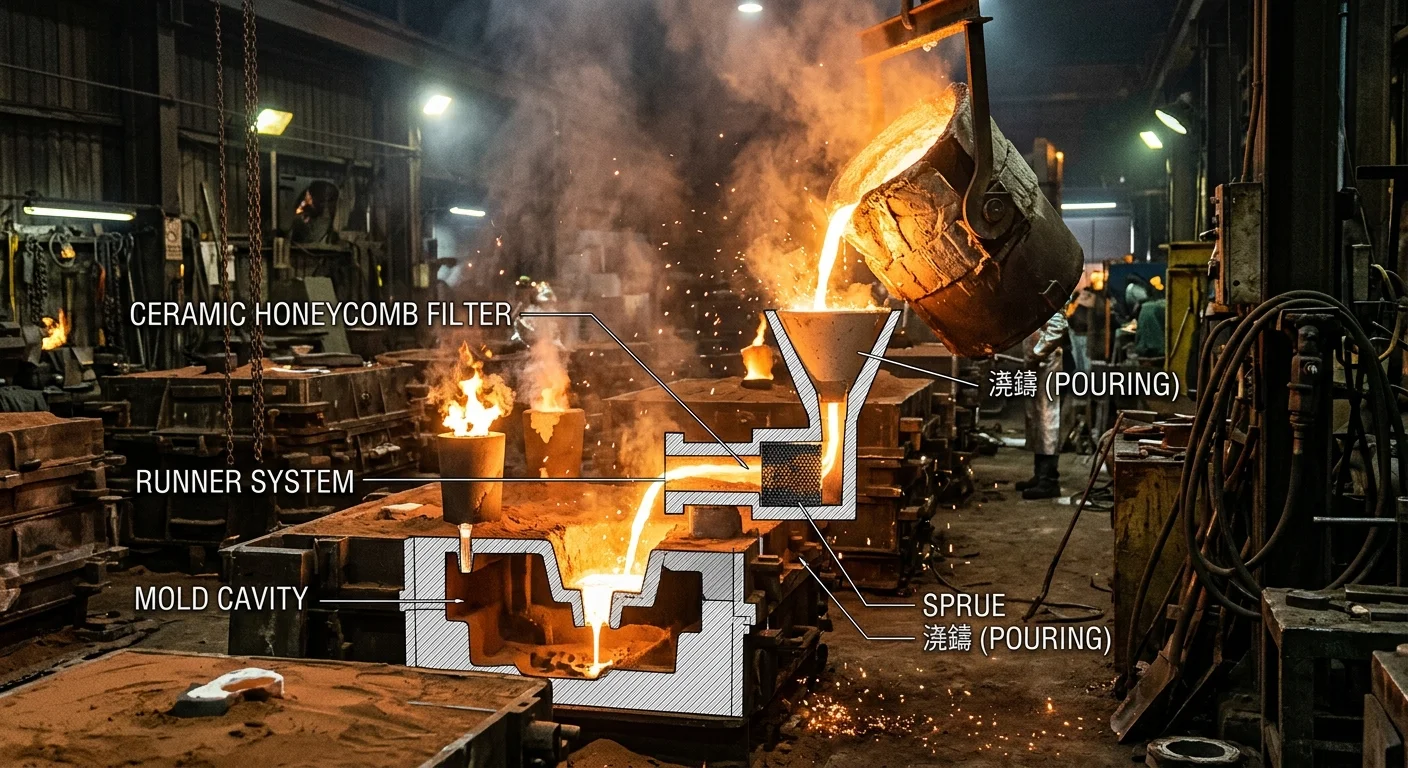
Molten metal is not cooperative. It carries slag, oxide films, sand grains, and reaction byproducts — none of which belong inside a finished casting. High-temperature filters for casting catch that contamination early. Get it right, and you never have to explain a defect to a customer.
These filters do three things at once.
First, they capture non-metallic inclusions — slag, dross, inoculant residues, sand particles. They do this by pushing the metal stream through a controlled pore structure. Second, they laminarize flow. Turbulent metal becomes a smooth, steady front. That steady front resists re-oxidation and stops air from getting trapped. Third, they regulate flow rate. Your gating system gets predictable, repeatable fill behavior — pour after pour.
Those functions sound simple enough. But filter selection is where foundries run into real trouble.
The Cost of Getting It Wrong
Pick the wrong filter and you get defects. There are four ways this happens:
-
Too fine (high ppi) for your flow rate → metal starvation, misruns, cold shuts
-
Too coarse (low ppi) → inclusions pass straight through
-
Wrong material for your alloy temperature → filter cracks, sheds fibers, or breaks apart mid-pour
-
Wrong placement in the gating system → turbulence comes back downstream of the filter
The financial hit is real. In ferrous foundries, non-metallic inclusions cause an estimated 20–40% of internal scrap. Switch from no filtration to a well-specified ceramic foam filter, and inclusion-related scrap drops by 50–80%. In Investment casting, a correct filter spec alone can push yield up by 2–5% per melt batch. For medium-sized shops running steel or superalloys, that number turns into six-figure annual savings.
Filter selection is a process variable. Treat it like one.
Ceramic Foam Filters: The Industry Standard for Iron, Steel, and Copper Alloys
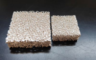
Ceramic foam Filters dominate ferrous and copper foundry practice for one simple reason: nothing else handles dirty, turbulent metal at high temperature with the same consistency and reliability.
The structural logic behind that dominance is worth understanding. A ceramic foam filter uses a reticulated 3D open-cell network — interconnected pores and ligaments that force molten metal to change direction as it flows through. That tortuous path does three things at once:
-
Mechanical sieving — inclusions larger than the pore window size get blocked
-
Deep bed filtration — smaller inclusions collide with ligaments, adhere, and agglomerate rather than passing through
-
Flow calming — turbulence drops, oxide re-entrainment minimizes, and your metal front steadies out
Straight-through cellular filters (like the CoorsTek Flow-Rite® honeycomb design) can’t replicate that last point. They’re engineered for consistent flow and low pressure drop — useful when throughput matters more than deep cleanliness. Ceramic foam wins where you need actual inclusion capture, sub-100 µm particles that straight-channel screens miss completely.
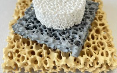
Three Materials, Three Temperature Windows
Not all ceramic foam is the same material. The variant you choose depends almost entirely on pouring temperature and alloy chemistry.
SiC (silicon carbide) — the workhorse for iron and copper
SiC ceramic foam handles pouring temperatures up to 1540–1560 °C. Compressive strength sits at ≥1.2 MPa at room temperature. Thermal shock resistance exceeds ΔT 1200 °C. That means it survives the thermal violence of a gray iron or Ductile Iron pour without cracking — as long as you’ve preheated it first.
It’s the default choice for: – Gray Iron (engine blocks, housings) poured at 1380–1450 °C – Ductile iron (safety-critical, nodularity-sensitive parts) poured at 1400–1500 °C – Copper alloys, bronzes, and brasses poured at 1100–1300 °C
SiC is the go-to option for all copper alloy castings. It combines high strength, thermal stability, and chemical resistance against oxidizing melts. The FM-10 CFF for copper is a practical example. It captures oxides and non-metallic inclusions through its 3D ceramic mesh. The result: better mechanical properties, higher electrical conductivity, and improved surface finish.
ZrO₂ (Zirconia) — when steel chemistry gets aggressive
Steel changes the calculation. Carbon steels, alloy steels, stainless steels, and nickel or cobalt superalloys pour at or above 1600 °C — past the safe working limit of SiC. zirconia foam handles up to 1750 °C. It carries a compressive strength of ≥2.5 MPa, the highest of the three materials. It also resists chemical attack from aggressive melt chemistry involving Mn, Cr, and Ni.
Your steel pouring temperature exceeds 1560 °C? Or your alloy contains elements that react with SiC at prolonged holding times? Zirconia is the safe choice. There’s no real alternative at those conditions.
Al₂O₃ (Alumina) — non-ferrous at lower temperatures
Alumina foam sits below both SiC and ZrO₂ in mechanical strength (≥0.8 MPa). It’s reserved for aluminum alloys and lower-temperature non-ferrous melts at or below 800–1000 °C. It doesn’t belong in iron or steel applications.
PPI Selection: Where Foundries Lose the Advantage
Choosing the right foam material gets you into the game. Choosing the right PPI (pores per inch) determines whether you win or lose on flow behavior.
|
Casting Type |
Recommended PPI |
Rationale |
|---|---|---|
|
Heavy gray iron sections |
10–20 ppi |
High flow, lower head loss |
|
Ductile iron (inclusion-sensitive) |
20–30 ppi |
Nodular iron punishes inclusions |
|
Large steel castings |
10–20 ppi (ZrO₂) |
Avoids misruns; captures larger inclusions |
|
Precision copper / thin-wall parts |
20–30 ppi |
Fine finish, improved conductivity |
For large or complex parts — axle bodies, cylinder blocks — staged filtration is worth the added complexity. Use 10 ppi in the main runner and 20 ppi closer to critical sections. You get flow where you need it and cleanliness where it counts.
The Trade-Offs You Need to Know
Ceramic foam filters cost 3–10× more per unit than fiberglass mesh screens. In aluminum and low-temperature non-ferrous work, that gap matters. In iron and steel, it’s a non-issue. The scrap cost of a single inclusion-contaminated pour erases the filter price differential fast.
The real operational risk with ceramic foam is thermal shock. CFFs are brittle. Hit a cold filter with full-temperature metal and you get cracking, spalling, and ceramic fragments in your casting — a worse outcome than running no filter at all. The fix is straightforward: preheat to 600–800 °C. At minimum, flame-dry the filter until surface moisture is gone and thermal gradients are reduced before any metal contacts it. SiC handles thermal shock better than alumina. Zirconia is highly refractory but just as brittle — treat it with the same care.
The Selection Rule in Plain Language
Working through material selection for a new job? This sequence covers most ferrous and copper casting scenarios:
-
Copper alloys and cast iron (1100–1500 °C) → SiC foam, 20–30 ppi for precision parts, 10–20 ppi for heavy sections
-
Steel and superalloys (≥1600 °C) → ZrO₂ foam, 10–20 ppi, parallel filters for very heavy pours
-
Edge case — very large iron castings at high superheat → consider moving from SiC to ZrO₂ if holding time is extended and chemical attack is a concern
Industry benchmarks on inclusion reduction for correctly specified ceramic Foam Filters run 30–60% versus unfiltered metal. For foundries running iron and steel at volume, that number translates straight into scrap reduction and margin recovery. The filter cost is incidental. The selection decision is not.
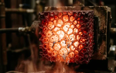
Honeycomb Ceramic Filters: Best Choice When Flow Rate Is the Priority
Flow rate kills more large castings than dirty metal does. A 2,000 kg iron housing misrun doesn’t care how clean your melt was. If the metal stalled before the mold filled, the part is scrap. That’s where honeycomb Ceramic filters earn their place.
The structural difference from ceramic foam is straightforward. foam filters push metal through a twisting 3D network — thousands of direction changes, collisions, and adhesion points. That design is what makes foam so effective at capturing sub-50 µm oxide films. But there’s a cost: pressure drop climbs as inclusions build up. In long pours, foundries see 20–40% flow rate decay through foam elements. For foam-filtered setups, that’s not a bug — it’s the physics.
Honeycomb filters use straight, parallel channels. The flow path runs close to linear. The hydraulic diameter is larger. The effective path length is shorter. Look at the pressure-drop relationship — ΔP scales with channel length divided by the fourth power of diameter — and the math favors honeycomb at high throughput. The result: flow rate stays stable even as inclusions build up. No channel-to-channel plugging cascade occurs the way it does in twisted foam pores.
Foundry trials comparing honeycomb against equivalent-area foam filters show fill times 10–20% faster. Pressure drop curves stay flat across the full pour duration. For Al Gravity casting, switching from 30–40 PPI foam to honeycomb with the same frontal area can deliver 1.3–1.8× higher flow at a similar pressure drop budget.
What Honeycomb Captures — and What It Doesn’t
Be precise here. Honeycomb filters are not foam replacements. They serve a different function in the filtration chain.
Straight channels do three things well:
-
Screen coarse slag and refractory chips — inclusions larger than 100–150 µm don’t make it through
-
Smooth flow — the channel geometry reduces turbulence at mold entry, cutting surface folds and entrained oxidation
-
Maintain consistent throughput — no progressive blockage, no cycle-time drift
What honeycomb doesn’t do: capture fine oxides below 50 µm. The twist-driven adhesion that makes foam work against sub-50 µm particles doesn’t exist in straight channels. Your melt carries a heavy fine-oxide load from poor upstream degassing? Honeycomb alone won’t fix that.
High-volume foundries handle this with a pairing strategy: honeycomb at the sprue or tundish outlet for throughput and coarse slag removal. Add a shorter low-PPI foam filter closer to the mold only when finer cleanliness specs demand it — and only when the pressure-drop budget has room.
Material Selection by Temperature
Two honeycomb materials cover most casting scenarios:
|
Application |
Material |
Temperature Limit |
|---|---|---|
|
Al, Mg, Cu alloys |
Mullite or cordierite |
Up to ~1200 °C (cordierite); 1500–1600 °C (mullite) |
|
Cast iron / carbon steel |
Mullite |
Up to ~1550 °C |
|
High-alloy steel |
Mullite (with caution) |
Switch to ZrO₂ foam above 1560 °C |
Cordierite gives you strong thermal shock resistance and low expansion. It’s the right pick for aluminum and nonferrous lines running below 1200 °C. Push it into ferrous territory and it softens. Mullite handles iron and lower-carbon steel pours without reacting with the melt or changing its chemistry.
Choosing Honeycomb Over Foam
Four conditions make honeycomb the better call:
-
Large-volume pours (1,000+ kg) — foam’s progressive pressure drop risks incomplete fill on big sections; honeycomb holds flow all the way through
-
Automated high-throughput lines — dimensional accuracy and flat surfaces allow reliable mechanical placement; stable flow keeps cycle times consistent
-
Thin-wall or complex gating designs — extra pressure drop causes cold shuts; honeycomb keeps metal velocity at what the gating calculation requires
-
Variable dross loads (secondary aluminum, contaminated returns) — in launders carrying dirty metal, foam elements plug and overflow; honeycomb channels keep passing metal even with some channels blocked
Flow rate is your binding constraint? Honeycomb is not a compromise. It’s the correct specification.
Fiberglass Mesh Filters: The Cost-Effective Solution for Aluminum Casting
Aluminum doesn’t need a $10 filter. It needs the right filter — and for most aluminum foundries, that’s woven fiberglass mesh.
The math is simple. Aluminum alloys pour between 680–760°C. Alumina fiberglass mesh runs at 700–800°C working temperatures, with a melting point around 900°C. That’s a tight but workable match. You’re not wasting thermal headroom, and you’re not paying for zirconia-grade refractory you’ll never use.
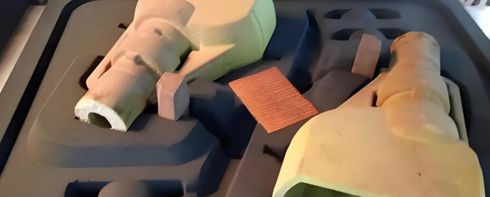
Construction and Available Forms
Fiberglass mesh filters for aluminum are woven from alkali-free or silica fiberglass yarn. These are high-twist, high-strength fibers that stay stable under pour conditions. Two surface treatment options cover most applications:
-
Resin-coated (brown) — standard aluminum filtration, general foundry use
-
Smokeless carbonized (black) — low gas output, no smoke or flame during pouring. The right pick for quality-sensitive parts like pistons
Forms vary to match your gating setup:
-
Flat sheets or rolls — cut to runner or sprue cross-section on-site with scissors. No special tooling, no lead time
-
Cap-style filters — sit in pouring cups or over sprue entries
-
Bag or combo filters — for ladle or launder filtration, catching dross before it reaches the mold
That cut-to-fit flexibility matters in high-mix environments. Ceramic foam blocks need holders machined to spec. Fiberglass mesh fits tapered runners, curved channels, and non-standard ingate geometry without any of that.
What Fiberglass Mesh Does to Your Melt
The filtration process runs in stages. First, the mesh geometry slows metal flow and dampens eddy currents. Second, the strands intercept slag, dross, and refractory particles. Third, captured inclusions build up on the mesh surface. The pore size tightens, and smaller particles that passed the first layer get caught. Fourth, the greater contact area pulls in finer contaminants through chemical adsorption.
Performance data backs this up. Baoding Ningxin reports slag-inclusion rejection rates dropping below 3% in aluminum castings with fiberglass mesh in place. Your baseline may sit at 5–8% — common in unfiltered or undertreated aluminum operations. That gap equals a 40–60% scrap reduction. The filter pays for itself inside a single production run.
There’s another economic factor most foundries miss: return scrap recyclability. Aluminum gating metal with fiberglass mesh goes straight back into the furnace for remelting. Metal quality stays intact. Sprue and riser returns reach 100% remelt utilization. That’s real alloy recovery, not theoretical.
Where Fiberglass Mesh Stops Working
Be clear about the limits. Fiberglass mesh handles coarse inclusions and agglomerates well — particles above 30–50 µm. Fine dispersed oxide films below 10 µm are a different problem. Mesh won’t solve that. No single filter type will.
For automotive wheels, pistons, rods, ingots, and general machinery castings, fiberglass mesh alone — or paired with basic flux treatment — gives you an acceptable cost-to-quality result. These applications have moderate defect tolerance and high cost pressure. Mesh fits.
For aerospace structural components, high-integrity hydraulic parts, or safety-critical thin-wall castings, the cleanliness standard goes beyond what mesh can handle on its own. The right approach: rotary degassing plus flux treatment upstream, then a 10–30 ppi ceramic foam filter for final polish. Fiberglass mesh can still sit in the Gating System as a first-stage coarse filter. It cuts the inclusion load before metal reaches the ceramic element, and that extends the ceramic filter’s service life.
Know where mesh stops. That’s what keeps you from asking it to do a job it was never built for.
Head-to-Head Comparison: Which Filter Works Best for Each Casting Scenario
Four filter types. Eight casting scenarios. One right answer for each.
This table isn’t here to give you options — it’s here to cut them down. Each scenario points to one best-fit filter. The match is based on temperature limit, inclusion removal rate, flow rate needs, and cost per unit. Use it to make a call, not to start a discussion.
The Verdict, Scenario by Scenario
General aluminum castings — wheels, housings, non-critical structural parts
Go with fiberglass mesh. You get 20–40% inclusion reduction at US$0.05–0.20 per gate. Flow stays high. Gating stays simple. Cost stays low. That’s the full case.
Critical aluminum — T6 heat-treatable, fatigue-loaded chassis parts
Run the hybrid stack: fiberglass mesh upstream + 20–30 ppi Al₂O₃ ceramic foam. The mesh breaks up dross and bifilms before they reach the foam. The foam catches the fines. Together, inclusion removal reaches 60–80%. The extra mesh cost is US$0.03–0.10 per box. On a rejected control arm, that number means nothing.
Aerospace aluminum and magnesium — radiography-inspected, strict cleanliness specs Move up to 30–50 ppi CFF with a pre-filter mesh, or run double CFF in series. This gives you the cleanest output available in gravity casting. Pressure drop is real — plan for it in your gating system.
Gray or ductile iron — machine beds, housings, general iron work
Use a pressed ceramic strainer (honeycomb) at the sprue base or runner. It handles 1,350–1,450 °C with no issues, delivers 30–50% straining, and costs US$0.50–2.00 per unit. Ceramic foam is more than you need here — unless you’re targeting ductile iron fatigue specs.
High-quality ductile iron — wind-turbine hubs, crankshafts, nodularity-sensitive parts
Switch to 10–20 ppi SiC or Al₂O₃ ceramic foam. Inclusion reduction climbs to 40–70%. That performance gap between honeycomb and foam is exactly where your crankshaft fatigue life is decided.
Carbon and low-alloy steel — valves, pump bodies, general steel castings Run a sintered wire or perforated steel strainer at the ladle lip or tundish to catch coarse slag. For parts that need higher cleanliness, add a zirconia CFF in the mold throat. Steel screens are reusable — spread over dozens of heats, the cost lands at US$30–100 per ladle frame. Save the zirconia for pours where UT inspection will expose every flaw.
High-integrity steel — pressure-containing components, turbine parts, UT-critical castings zirconia ceramic foam filter (10 ppi) in the gating system. Full stop. ZrO₂ holds up at 1,650–1,750 °C, continuous. Inclusion removal reaches 20–50%, even at high superheat and with aggressive alloy chemistry. No other filter handles those conditions without breaking down or contaminating the melt.
Copper alloys — bronze, brass, plumbing fittings, bushings Use 10–20 ppi Al₂O₃ ceramic foam in the pouring cup or runner. At 1,150–1,250 °C, fiberglass mesh is at its limit — dissolution is a real risk. SiC foam is the solid choice here. Inclusion removal lands at 40–70%. You’ll see the difference in surface finish and conductivity on finished parts.
One Rule That Covers All of It
Temperature limit picks your material. Flow rate picks your pore size. Chemical compatibility ties it together. Every scenario above follows that order. Work through those three steps, and the right filter becomes clear on its own.
How to Select the Right High-Temperature Casting Filter: 5 Key Decision Factors
Five variables decide whether your filter choice holds up or costs you. Get them all right, and scrap rates drop. Miss one, and the other four won’t save you.
Factor 1: Pouring Temperature vs. Filter Material
Temperature is the hard limit. Every other decision fits inside it.
-
680–770°C (aluminum) → fiberglass mesh or alumina ceramic foam
-
1100–1250°C (copper, bronze, brass) → SiC ceramic foam or honeycomb
-
1350–1500°C (cast iron) → SiC foam, rated to 1550–1600°C
-
1550–1650°C (carbon/low-alloy steel) → ZrO₂ foam
-
1650–1700°C+ (nickel/cobalt superalloys) → premium zirconia, 20–40 PPI, certified for continuous use above 1700°C
Ask your supplier for a max continuous-use temperature certification. No cert? Don’t use that filter for steel or superalloy work. Full stop.
Factor 2: Cleanliness Specification
Set your reject target first. Then pick the filter that hits it.
-
>2–3% inclusion scrap acceptable → fiberglass mesh or basic ceramic strainer. Catches coarse particles above 0.5–1 mm.
-
1–2% target → 10–20 PPI ceramic foam. Removes inclusions down to 100–300 µm.
-
<1% target (aerospace, medical, pressure-tight) → 20–40 PPI foam, often staged. Captures down to 30–100 µm.
See “critical,” “safety-rated,” or “pressure-tight” on the spec sheet? Go with high-PPI foam matched to your temperature range. Filter cost is secondary at that point. One rejected part can cost more than a full month of premium filters.
Factor 3: Flow Rate, Filter Sizing, and PPI
A filter that stalls your fill is a defect waiting to happen. Size the filter area against your gating geometry — not just your cleanliness target.
-
Aluminum: filter frontal area ≈ 1.2–1.5× the choke area. Target superficial velocity 0.3–0.8 m/s.
-
Iron and steel: size to 1.5–2.5× choke area. Hold velocity to 0.2–0.5 m/s.
PPI selection flows from there:
|
PPI |
Use Case |
|---|---|
|
10 PPI |
Large castings, short pour windows, flow-critical |
|
20 PPI |
Standard aluminum and iron work |
|
30–40 PPI |
High-cleanliness specs — pair with larger filter area or parallel elements |
Your cleanliness spec calls for 30+ PPI but your flow rate can’t handle the pressure drop? Run multiple filters in parallel in a split runner. Don’t push a single fine-PPI element past what it was built for.
Factor 4: Production Volume and Cost Sensitivity
The break-even math is simple. Run it before you lock in a filter spec.
Monthly recovered margin from upgrading filters = N × V × (S₁ – S₂)
-
N = castings per month
-
V = margin per accepted casting
-
S₁, S₂ = scrap rates before and after filter upgrade
Example: 10,000 aluminum castings/month at $10 margin each, scrap drops from 3% to 1%. Recovered margin = $2,000/month. Ceramic foam at $0.80 vs. mesh at $0.20 adds $6,000/month in filter cost. Upgrade not justified.
Flip that to $100-margin castings: recovered margin jumps to $20,000/month. The $6,000 premium pays back three times over.
The rule: – High-volume, low-margin, non-critical parts → stay with fiberglass or low-cost ceramics. – Low-volume, high-value, critical parts → premium foam. – One scrapped turbine housing covers the cost of hundreds of Zirconia filters.
Factor 5: Casting Geometry
Shape decides where the filter goes and what format works.
Thin walls and long flow paths need a smooth, heat-stable fill. Use 10–20 PPI foam with enough frontal area. Place it close to the cavity. Don’t bury it deep in the runner system — that gives re-oxidation room to build up before the metal reaches the mold.
Complex gating with multiple ingates works better with several smaller filters per branch. One large upstream element is the wrong call here. With smaller per-branch filters, velocity drops at each ingate, flow spreads out evenly, and no single filter has to manage an entire multi-gate system on its own. Flat honeycomb elements fit well into rectangular runner sections — the shape works with you, not against you.
Work through these five factors in order. Temperature sets your material. Cleanliness spec sets your PPI. Flow rate sets your sizing. Volume and margin set your cost ceiling. Geometry sets your format and placement. The right filter becomes clear. Guessing stops.
Common Mistakes When Choosing Casting Filters (And How to Avoid Them)
Most filter failures aren’t random. They follow a pattern. That pattern traces back to one of four decisions made before the first drop of metal moved.
Mistake 1: Wrong Filter Material for the Temperature
Fiberglass mesh burns through in 5–10 seconds at steel pouring temperatures. Al₂O₃ foam starts dissolving at 1,620°C. It sheds alumina stringers straight into your melt. SiC oxidizes in aggressive steel atmospheres. The result: silica films and pinhole porosity.
The fix is simple. Match material to temperature. Leave no room for optimism.
-
Al and Cu alloys → alumina foam or fiberglass mesh. ZrO₂ here costs 30–60% more than you need to spend.
-
Steel above 1,600°C → ZrO₂ foam, no exceptions.
Mistake 2: Skipping Preheat
A cold ceramic filter meets 1,400°C metal. That’s a thermal shock of over 1,300°C ΔT in seconds. Radial cracks form fast. Filtration efficiency drops — and you won’t see it happen. You’ll spot it later as random large inclusions near filter edges.
Minimum targets: >250°C for aluminum, >500°C for steel filters. Put a numeric temperature checkpoint on your pre-pour checklist. Not a reminder — a number.
Mistake 3: Undersizing the Filter Area
Too much velocity through a small filter causes premature blockage, pressure drop, and eventual blow-through. The math is simple:
-
Find flow rate Q = W ÷ (ρ × tₚ)
-
Divide by the recommended max velocity: 0.15–0.25 m/s for aluminum, 0.05–0.15 m/s for steel
A 600 kg steel pour through a 100×100 mm ZrO₂ filter runs about 2× undersized. Step up to 140×140 mm, or run parallel elements.
Mistake 4: Over-Specifying When It Doesn’t Pay
Inclusion-related scrap already below 0.5–1.0%? Switching to ZrO₂ for aluminum won’t recover that cost. Pull six months of defect data. Split out inclusion failures from misruns, shrinkage, and porosity. The filter may not be the real problem. Don’t pay premium filter prices for a fix that won’t move the needle.
Conclusion
Picking the right high-temperature filters for casting isn’t about finding the “best” filter on paper. It’s about finding the best filter for your specific pour.
Ceramic foam filters lead where cleanliness matters most. honeycomb ceramics work best when flow rate drives your decision. Fiberglass mesh keeps aluminum operations simple and cost-effective. The wrong filter costs you more than a bad casting. It costs you time, higher scrap rates, and credibility on the floor.
Three things to take with you:
-
Match the filter to the metal, not to habit or convenience
-
Check temperature, porosity, and flow rate before you buy
-
Cheap filters on critical pours are the most expensive mistake you’ll make
Now it’s your move. Look at your current filtration setup. Compare it against the scenarios covered here. Something doesn’t fit? Fix it before your next production run — not after.
The best casting filter is the one you picked on purpose.