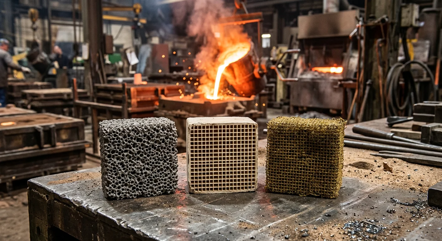
Scrap rates don’t lie. A porous casting, a cold-shut, or one riddled with inclusions — the filter choice is often the culprit nobody wants to name. ceramic foam vs. honeycomb vs. fiberglass Foundry filters — this isn’t just an academic debate. It’s the difference between a production line that runs clean and one that bleeds money on rework.
Each filter type has a specific job it handles well. Each also has a set of conditions where it lets you down. This guide breaks down the real performance differences across six critical dimensions. You’ll get a practical decision framework for matching filter to casting scenario. Plus, it covers the operational details that most spec sheets skip over.
No filter beats every other in every situation. The right pick depends on what you’re pouring, what defect rates you can live with, and what your scrap numbers say.
What Makes a Foundry Filter Work?
Four things decide whether a foundry filter belongs in your gating system — or silently fills your scrap bin by Friday. Filtration efficiency. Flow rate stability. Thermal tolerance. Total cost of ownership. Get all four right, and the filter does its job. Miss even one, and the numbers go bad fast.
You can’t optimize one parameter and ignore the rest. Filter thickness, pore size, and material grade all affect each other. A thicker filter increases flow resistance. As inclusions build up during the pour, that resistance keeps rising. Size the system wrong for your melt temperature or impurity load, and the filter stalls — a stalled filter is worse than no filter at all.
The 4 Parameters, Defined
1. Filtration Efficiency
The filter needs to trap both external and internal inclusions: slag, foam, and oxide-based impurities. Ceramic filters handle this two ways: – Surface sieving — catches particles too large to pass through the pores – Deep-bed capture — pulls in smaller particles as metal moves through the filter body
Beyond trapping particles, a well-matched filter also evens out metal flow and slows it down. This shifts turbulent melt toward a smoother, more controlled flow. That shift matters. Turbulence causes re-oxidation and sand erosion — two major defect sources. Good filtration cuts both.
2. Flow Rate Stability
Filters aren’t just passive screens. They need to keep metal delivery consistent from the first pour to the last. Inclusion buildup tightens resistance over time — not all at once, but steadily. For larger castings with longer pour times, set up multiple gating process options in advance. This gives you a practical backup if buildup starts slowing the fill.
3. Thermal Tolerance
The filter must hold up through the entire pour — not just the opening seconds. different ceramic materials have different heat limits: – Zirconium silicate – Zirconium oxide – silicon carbide – Mullite
Each one handles temperature differently. Ask your supplier to confirm durability against your specific casting temperature, pour height, and fill time. A filter that breaks down mid-pour puts contamination directly into the melt it was supposed to clean.
4. Total Cost of Ownership
Unit price is the wrong thing to focus on. The real cost picture includes scrap reduction, fewer reworks, lower machining cleanup costs, and fewer non-fills. In Investment casting, steady filtration cuts rework often enough to turn the filter into a cost-control tool — not just a quality checkpoint.
Quick evaluation checklist:
– Can it hold back slag, oxide, and foam inclusions?
– Will flow stay steady as inclusions load up?
– Is it rated for your casting temperature and pour duration?
– Does defect reduction cover the added gating and filter cost?
Match all four, and the filter pays for itself. Miss one, and it won’t.
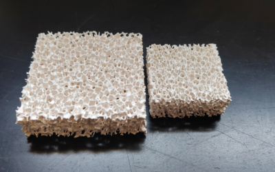
Ceramic Foam Filters: Maximum Inclusion Capture for Critical Castings
Ceramic foam Filters earn their place in the Gating System the hard way — by catching what everything else misses.
The mechanism behind that performance is straightforward. Molten metal doesn’t flow straight through a CFF. It pushes through an interconnected 3D pore network, shifting direction at every turn as it moves through the irregular internal structure. Each turn creates another collision point between an inclusion and a ceramic strut. That’s not an accident of design — it’s the entire point. This tortuous-path capture is why ceramic foam outperforms straight-channel honeycomb and simple mesh. Fine inclusion removal is where it pulls ahead.
The result is deep-bed filtration, not just surface sieving. Inclusions get trapped throughout the filter body, not piled up at the face. In high-purity aluminum applications, that means pulling out particles down to 5 μm. That’s well below what the pore diameter alone would lead you to expect.
PPI Selection: Where Fineness Meets Flow Reality
PPI — pores per inch — is the main control point for balancing filtration quality against flow rate. Get the tradeoff wrong, and the filter works against you.
-
10–20 PPI: Coarse. Higher flow capacity. Best for large, heavy castings and high-volume pours where metal throughput matters more than ultra-fine cleanliness.
-
30–40 PPI: The workhorse range. This covers most gravity die casting and quality sand casting applications.
-
50–60 PPI: Reserved for aerospace, aviation, and thin-wall automotive parts. Flow takes a hit. Cleanliness doesn’t.
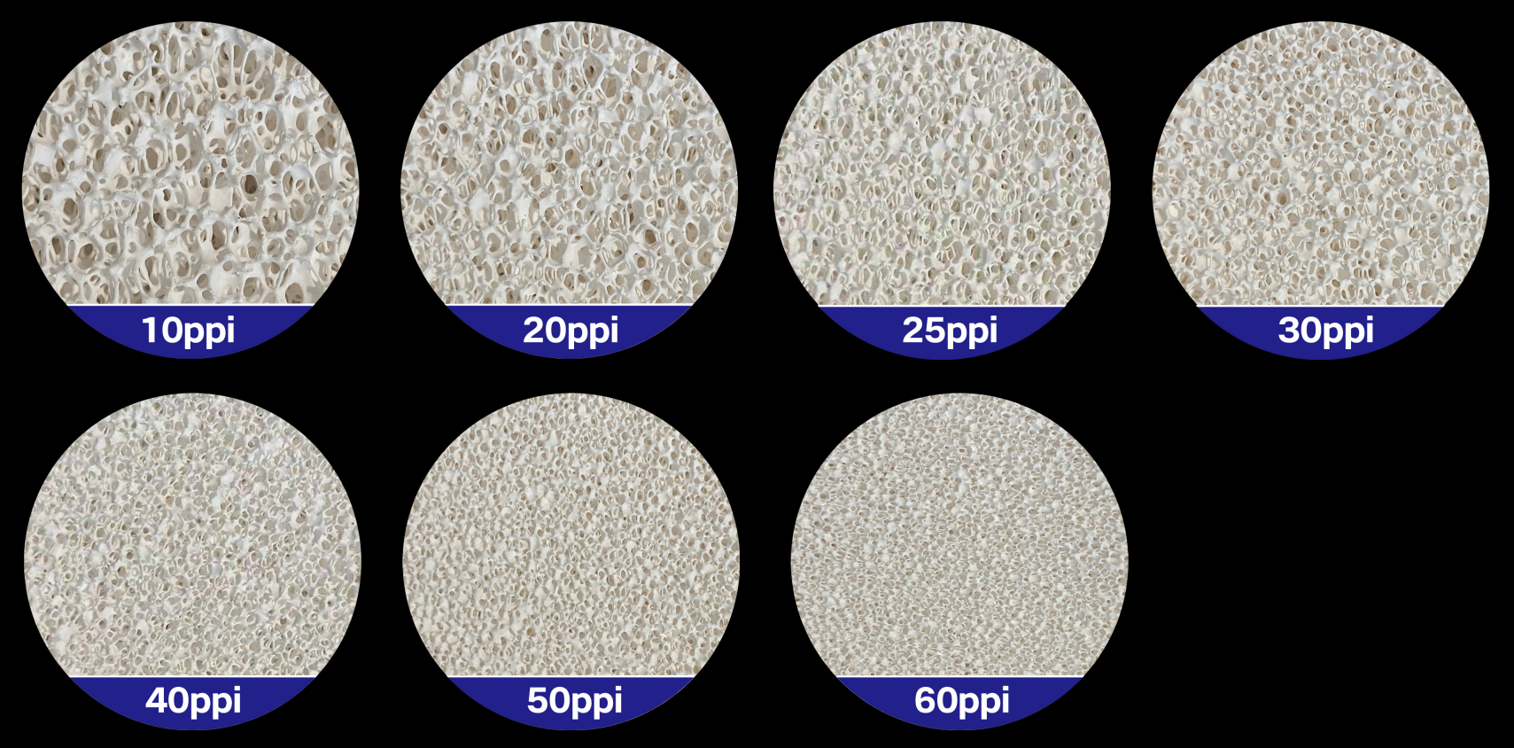
Commercial alumina CFF plates run 25–90 PPI, available in sizes from 7×7 in to 26×26 in. The range gives you room to match the filter to the pour — but you need to choose with a clear purpose.
Managing Progressive Clogging
Clogging isn’t a failure mode. It’s a physics certainty. As inclusions build up in the pore network, the usable flow area shrinks and resistance rises — bit by bit, not all at once. For large pour volumes or dirty melts, that buildup matters.
Four practical adjustments keep clogging from killing the pour:
-
Upsize the filter area rather than forcing high velocity through a small filter
-
Drop to a lower PPI when the melt carries a heavy inclusion load
-
Use a filter box to stabilize flow and control turbulence around the filter
-
Position the CFF as the final purification stage before the mold cavity — this cuts re-oxidation and dross entrainment right at the most critical point
Material Grade Sets the Temperature Ceiling
Alumina (Al₂O₃) handles aluminum casting well, rated for continuous service up to 1,100°C. For higher-temperature ferrous and nickel alloy work, that ceiling falls short. SiC and ZrO₂ variants take over where alumina runs out of range. Material selection isn’t a side note. It’s a hard limit.
What the Numbers Say
Correct alumina CFF application cuts scrap by 15% to 40% by reducing internal inclusions and surface defects. That range is wide because the gain ties back to how dirty the baseline melt is and how well the filter matches the pour. The cleaner your starting metal, the smaller the improvement. The dirtier the melt, the more the CFF gives back.
For automotive structural parts, aerospace castings, and premium aluminum alloys, the math tends to land in the same place: defect cost justifies the added filter cost and the flow penalty that comes with tighter filtration.
The selection rule is simple: critical part, high defect cost — go higher PPI with a larger filter area and tighter gating control. Large pour, dirty melt — put flow capacity and clogging margin ahead of maximum fineness. It’s one or the other. Getting both at once is rare.
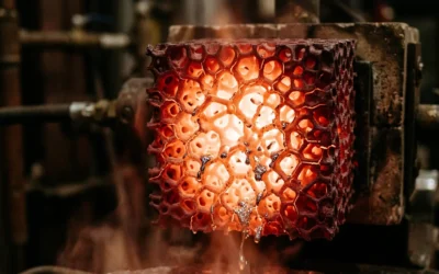
Honeycomb Ceramic Filters: High-Throughput Stability for Production Lines
Flow rate doesn’t lie. On a high-volume iron line, you can tell which filter is pulling its weight by the third hour of a shift.
Honeycomb ceramic filters are extruded cordierite or mullite structures. Straight, parallel channels. Thin walls. The geometry is simple by design. Ceramic foam pushes metal through a winding 3D maze that clogs over time. Honeycomb channels stay open. Metal velocity stays predictable. Fill times hold steady pour after pour.
The numbers back this up. A 150–200 cpsi Honeycomb filter running dirty iron holds a near-constant flow rate over a full shift. A foam filter at a comparable filtration level? You’re looking at a 20–30% flow reduction over the same pour sequence as inclusions pack the tortuous path. On an automated line feeding multiple molds per minute, that kind of drift causes real problems — cold shuts, misruns, and mechanical property variation across the lot.
Thermal Ceiling and Mechanical Reliability
Cordierite-mullite construction sets the working temperature at 1,350–1,390°C. That range covers gray iron, ductile Iron, and most high-temperature aluminum applications — no material substitution needed. For production environments, there’s another key point: these filters handle thermal shock without cracking.
Rapid preheat, immediate metal contact — the structured geometry spreads melt impact across multiple thin walls. Foam concentrates stress at irregular struts. Honeycomb doesn’t.
Fragment release risk on automated lines needs to stay below 1–2% across thousands of pours. Dense extruded honeycomb holds that standard. Transit breakage runs 0.1–0.3%. Foam filters requiring careful manual handling see 1–2% breakage by comparison.
Why Automation Lines Prefer the Geometry
Honeycomb filters hold tight dimensional tolerances — ±0.5–1.0 mm on length and width. That makes them automation-compatible. Foam Filters rarely meet that bar. Robots place honeycomb filters without issue. Bowl feeders run them at pace. Misfit rates drop below 0.5% of molds once tolerance holds.
The extruded structure resists warping during preheat. So you can run standardized preheat curves of 600–800°C for 10–20 minutes across the full line — no per-batch adjustment needed. Fix your gating and temperature, and fill time variation locks in at ±5%.
The Trade-Off Worth Knowing
Honeycomb doesn’t match ceramic foam on ultra-fine inclusion capture. Foam’s complex internal surface area pulls particles below 20–30 µm with more efficiency. Pouring aerospace-grade aluminum or ultra-clean steel where every micron counts? Foam still wins on cleanliness.
But for ductile iron transfer lines, Gray Iron production casting, and high-throughput automotive applications where melt cleanliness shifts lot to lot — honeycomb is the more process-stable choice. It filters better than fiberglass. It delivers more stable flow than foam. And the geometry your automation system can actually work with.
Fiberglass Filters: The Low-Cost Option (And Where It’s Enough)
Cost-per-piece is the whole argument for fiberglass. Full stop.
Spun glass media. Flat panel. Cardboard frame. No engineering mystery here. The design is simple on purpose. That simplicity keeps the unit price low — often under $3 per panel in volume. For buyers where per-piece cost drives every decision, that number is tough to beat.
But the performance ceiling is just as real as the price tag. Fiberglass captures less than 25% of particles in the 3–10 micron range. Fine particles pass straight through. The open, porous media keeps airflow moving freely — but that same structure lets contaminants slip through too.
Where Fiberglass Makes Sense
Here’s the straight answer: fiberglass works in non-critical applications with moderate cleanliness targets. You need low pressure drop more than fine particle capture.
Three conditions need to line up before fiberglass is the right call:
-
Lowest unit cost is the primary decision driver
-
Moderate inclusion levels are acceptable for the application
-
High flow / low restriction outweighs fine particulate removal
All three line up? Fiberglass fits. But any one of those breaks down — structural parts, tight defect tolerance, dirty melt — step up to foam or honeycomb instead. Fiberglass won’t cut your scrap rate if it can’t catch the particles causing the scrap in the first place.
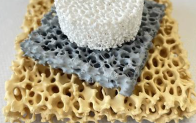
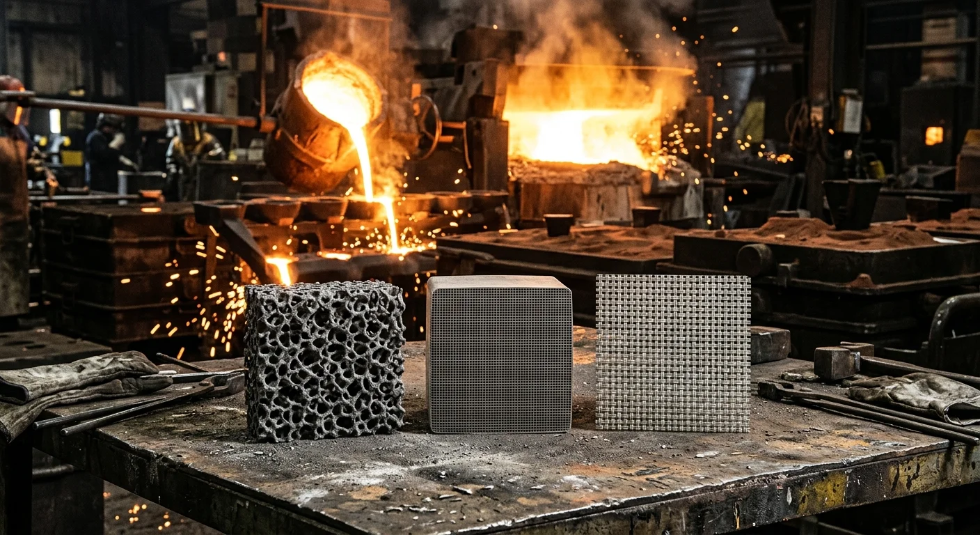
Head-to-Head Comparison: Ceramic Foam vs. Honeycomb vs. Fiberglass Across 6 Key Dimensions
Six numbers tell the story. Run all three filters through the same conditions. The performance gaps are hard to ignore.
|
Dimension |
Ceramic Foam |
Honeycomb Ceramic |
Fiberglass Mesh |
|---|---|---|---|
|
Inclusion removal |
60–80% reduction (Al) |
30–50% reduction |
15–30% reduction |
|
Pressure drop (clean) |
2–20 kPa |
1–5 kPa |
<1 kPa |
|
Flow under clogging |
Drops 20–50% in stages |
Near-constant until sudden blockage |
Gradual, linear decline |
|
Max temperature |
Up to 1,700°C (ZrO₂) |
Up to 1,400°C (cordierite/mullite) |
~700–800°C ceiling |
|
Surface defect reduction |
30–60% vs. unfiltered |
Noticeable, but less than foam |
Modest — large dross only |
|
Cost per piece |
$1–30 depending on grade |
10–30% cheaper than foam |
$0.10–0.50 |
What the Numbers Mean in Practice
Filtration efficiency is where ceramic foam pulls ahead of everything else. In documented aluminum wheel casting cases, ceramic foam dropped the density index from 6–8% down to 2–3%. It also cut radiographic oxide indications in half. Honeycomb brought the same metric to 4–5%. Fiberglass managed 1–2 percentage points of improvement — often within measurement scatter, so the gains are hard to confirm.
Flow behavior under load is where real operational risk shows up. Ceramic foam clogs in stages. Permeability drops across the full 3D network as inclusions build up. Plan for a 20–50% flow reduction during long, dirty pours. Honeycomb holds near-constant throughput up to a breaking point. Most channels stay open, then several block at once. Velocity spikes in the remaining channels. Re-entrainment risk jumps fast. Fiberglass loads up at the surface at a steady rate, but stays manageable in short pours.
Temperature ceiling is a hard limit, not a rough guide. Fiberglass tops out at aluminum temperatures — nothing beyond that. Cordierite honeycomb handles iron. zirconia foam reaches steel and nickel alloys.
Cost only makes sense against scrap savings. A $0.50 fiberglass pad that misses the inclusion causing a $200 rework isn’t cheap. At that point, you’re paying more than you saved. Price per piece means nothing without counting what bad filtration costs you downstream.
How to Choose the Right Filter: A Decision Framework by Casting Scenario
Four gates. That’s the entire decision process. Work through them in order, and the right filter picks itself.
Gate 1: Alloy Temperature — Eliminate First
Start by ruling out what can’t survive your melt. The alloy-temperature match is straightforward:
-
Aluminum alloys — the most forgiving group. All three filter types work. Cost is the real differentiator.
-
Copper alloys — higher heat, more oxidation pressure. Ceramic-based filters move to the front.
-
Iron and steel — fiberglass is out. Full stop. High-temperature ceramic is your lane. There’s no other option.
-
Nickel-based alloys — the most demanding application in the group. Ceramic foam is the default first pick. Both temperature demands and cleanliness requirements point the same way.
Your alloy is running near the filter medium’s rated ceiling? Don’t push that limit on a production pour.
Gate 2: Cleanliness Requirement
How expensive is a defect? That question does more work here than any spec sheet.
-
High-value part, tight defect tolerance, expensive scrap → ceramic foam. Its inclusion capture ability justifies the higher price.
-
Moderate spec, manageable scrap cost → fiberglass clears the bar. Don’t overpay for cleanliness you don’t need.
Gate 3: Flow Stability
Running a high-throughput, automated line? Flow variation is a production problem, not just a quality problem. Honeycomb holds near-constant throughput. Foam slows down under inclusion load over time. The line runs continuous and cadence matters? Honeycomb earns its place — settle flow stability first, then fine-tune cleanliness.
Gate 4: Unit Cost vs. Scrap Cost
Run the math before committing. Say the ceramic foam premium is $0.60/piece. The break-even is simple: scrap reduction per casting × rework cost per rejected part ≥ $0.60. It clears that threshold? The upgrade pays for itself. It doesn’t? Fiberglass is the right call — not the cheap call.
One hybrid worth knowing: fiberglass pre-filter upstream, ceramic foam downstream. Coarse contamination burning through expensive foam too fast? The two-stage setup extends foam life and cuts total cost per casting. It works as long as the fiberglass stage pulls out bulk debris without creating a flow bottleneck.
Installation, Sizing, and Operational Tips for Each Filter Type
Getting the filter selection right is half the job. A ceramic foam filter with perfect specs still fails if you seat it with a 3 mm gap on one side. A cheaper filter, sealed tight, will outperform it. The installation details are where good theory produces bad outcomes.
Ceramic Foam Filters
PPI selection by application:
– 10 PPI — heavily contaminated melts, large section castings, cast iron with heavy slag load. Low pressure drop, high flow.
– 20 PPI — general-purpose aluminum, copper alloys, non-safety automotive. This is the standard go-to choice.
– 30–60 PPI — aerospace and critical automotive aluminum. You need ≥250–350 mm of metallostatic head above the filter. Short on head pressure? Expect misruns.
Sizing rule: Design for ≤60–70% of vendor-rated capacity. That extra margin handles inclusion buildup during the pour. Aluminum flows at 7–15 kg/min per cm² at 10–20 PPI. Step up to 30 PPI and derate that figure by 30–50%.
Seating: Machine the seat to 0–1 mm clearance per side. Wrap a 10–15 mm ceramic fiber gasket around the full perimeter — no gaps over 1–2 mm. Ram the surrounding sand tight. A bypass channel around the filter face shuts down filtration completely.
Thermal practice: Preheat to 600–800°C before first metal contact. Use a wide, soft flame — never a single point. Moisture trapped under the filter causes spalling or blow-through.
Honeycomb Ceramic Filters
Place the filter in the runner after the sprue well, before runner splits. Keep 2–3 hydraulic diameters of straight runner both upstream and downstream. Flow must enter at a right angle to the filter face. Skew beyond ±5–10° and you get channel preference plus uneven clogging.
Gating geometry: Size the filter cross-section at 1.2–2.0× the upstream runner area. Target downstream velocity of 0.3–0.6 m/s for aluminum, 0.4–0.8 m/s for iron. Add a straight calming length of ≥3–5× the runner hydraulic diameter before any gate entrance or 90° turn.
Fiberglass Mesh Filters
Cut the mesh 2–5 mm larger per side than the seat opening. Overlap onto the seat by at least 8–15 mm all around. Pull it taut before closing. Wrinkles create weak stress points — metal jets straight through them.
Support spans matter: Spans beyond 20–30 mm without support fail under aluminum head loads. Keep metallostatic head at ≤400–600 mm over unsupported mesh for aluminum. For iron, drop that to ≤200–300 mm — unless you back the mesh with a ceramic or metal frame.
Temperature exposure: Standard E-glass softens at 700–800°C. That works for aluminum, not iron. For iron and steel, use high-silica or coated fiberglass rated to 1,250–1,400°C. Even then, limit contact time to under 30–60 seconds. Do not preheat fiberglass above 400–500°C in open air. Long exposure breaks down the glass structure before the first pour even starts.
Conclusion
No filter is “best” for every situation. The right choice depends on your specific metal, your acceptable defect rate, and your production economics.
Ceramic foam is the go-to for strict inclusion control. Honeycomb makes more sense where throughput and thermal consistency outweigh fine filtration. Fiberglass fits when the application has room for error and the budget is tight.
Most comparison guides hide that answer in vague language. This is the straight version.
So here’s your next move. Take your most problematic casting — the one producing the most scrap or drawing the most customer complaints. Run it through the decision framework above. Match the failure mode to the filter. Start there.
Still unsure which filter geometry and pore rating fits your pour conditions? Talk to your filter supplier with spec sheets in hand — not catalog pages. A single focused conversation with the right data on the table is what separates a good filter choice from a great one.