Pick the wrong ceramic filter and you’ll know it fast—clogged gates, cold shuts, or a foundry floor covered in scrapped castings that looked fine right up until they didn’t. A filter engineered for clean aluminum flow will fail in a 1600°C steel pour, and the reverse is just as true. Choosing the right ceramic filter for ferrous and non-ferrous casting means matching material chemistry, pore structure, and placement to your specific alloy and gating design. This guide breaks that process down into eight practical steps, covering foam versus honeycomb structures, porosity selection, and correct sizing—so you can stop chasing inclusion defects and start filtering with confidence, whether you’re working with molten aluminum or high-alloy steel.
Ceramic Filter Core Functions in Metal Casting
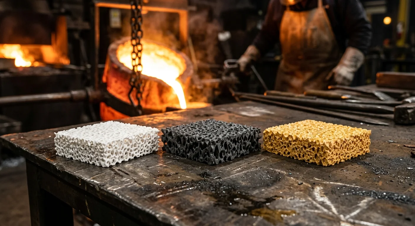
A ceramic filter strips out non-metallic inclusions and calms turbulent flow into laminar streams. foam ceramic filters—typically Al₂O₃, SiC, or ZrO₂ with 80–90% porosity and 10–30 PPI—catch oxide films, slag, and sand particles through mechanical screening. The filter traps particles larger than 0.5mm almost instantly; as a cake layer builds, it removes 60–90% of even 10–100 micron oxides. Inside the filter’s tortuous channels, deep filtration takes over. SiC’s glassy surface layer softens under molten metal heat, chemically bonding with inclusions as small as 20–30 microns—far smaller than the pore openings themselves.
Step 1: Match Filter Material To Metal Type & Pouring Temperature
Temperature decides everything here. Get the metal-to-filter match wrong, and you’re not filtering—you’re melting your own filter into the casting. Three ceramic chemistries dominate foundry floors: alumina, silicon carbide, and zirconia. Each one owns a specific temperature lane, and crossing that line is where scrap rates spike.
Aluminum & Aluminum Alloys (680–780°C typical pour)
Alumina-based CFF is the default choice, rated for continuous service up to 1100–1200°C. That gives you a 300°C+ safety margin. Standard filters run around 60% Al₂O₃, but if you’re pouring high-magnesium alloys like 5083 or 5182 (Mg >4%), bump up to 99% Al₂O₃ or switch to SiC. Magnesium is aggressive and eats through low-purity filters fast. Preheat filters to 400–600°C before contact to avoid thermal shock.
Copper Alloys (900–1250°C)
Below 1100°C, alumina CFF works fine and keeps costs down. Push past that toward 1250°C, and you need SiC CFF, rated safely to 1500°C (some manufacturers claim 1530°C).
Gray & Ductile Iron (1200–1450°C)
SiC is the standard here too—thick 30–40mm sections, capped at 3 kg iron/cm² throughput.
Carbon Steel, Alloy Steel & Stainless (1550–1650°C)
Only zirconia (ZrO₂) CFF survives this range, rated to 1700–1760°C. SiC tops out at 1500°C—too low for steel.
Step 2: Choose Filter Structure Type — Foam vs Extruded/Honeycomb
Two structures dominate the ceramic filter market, and they solve different problems. Pick based on flow rate and cleanliness targets.
foam Ceramic filters use a reticulated, three-dimensional open-cell structure. Metal doesn’t travel in a straight line; it winds through a tortuous path, which creates deep-bed filtration. Porosity sits at 70–90% by volume, with pore size rated in PPI (pores per inch): 10 PPI for coarse filtration, 30 PPI for fine. This structure dominates aluminum, copper, and brass casting, and it’s also the standard for iron, where longer fill times make Deep filtration practical.
Extruded/honeycomb filters run straight channels instead. Pressed honeycomb uses cell diameter (commonly 2.5mm) to define porosity; extruded versions use CSI (cells per square inch). No tortuous path means lower overall porosity but also lower pressure drop, which matters when you’re pouring high-volume iron or aluminum through thick-wall gating on tight fill-time windows.
Where each wins:
-
Steel and high-cleanliness aluminum → high-PPI foam (20–30 PPI). Honeycomb rarely shows up in steel applications; foam’s filtration depth is worth the pressure drop.
-
High-flow-rate iron or large-section aluminum runners → honeycomb. Larger open area means predictable flow, lower pressure drop, easier gating math.
-
Cost-sensitive, high-volume production → honeycomb costs less to manufacture (extrusion vs. PU-foam ceramic coating and sintering). Foam costs more but pays off on high-value castings where scrap reduction offsets the price.
Maintenance matters. Foam traps debris in multiple internal layers, which is fine for single-use Foundry filters but hard to backflush. Honeycomb’s straight channels clean easily with reverse airflow, better suited to reusable filtration setups.
Step 3: Select Correct Porosity (PPI) For Your Casting
PPI determines whether a casting fills clean or freezes mid-pour. Choose filtration over flow and you’ll pay for it at the wrong moment.
Coarse end: 10–20 PPI
Heavy castings need volume, not fine screening. Ductile iron, large Gray Iron sections, and heavy steel castings run best at 10 PPI, prioritizing throughput over polish. Filter working area should be 4–6x the choke area of your gating system. Undersize that ratio and you’ll strangle pour speed regardless of PPI rating. Aluminum billet and continuous/semi-continuous casting sit in a wider 10–30 PPI band, depending on section thickness.
Mid-range: 20–30 PPI
This is your default zone for gray iron, Malleable Iron, and most non-ferrous alloys. 20 PPI balances inclusion capture against flow rate for general castings. 30 PPI is the most common industrial grade for aluminum—Sand casting, gravity die casting, semi-continuous work. Typical throughput sits at 800–1500 kg per filter. If you’re unsure where to start on a standard aluminum job, 30 PPI is the safe default.
Fine end: 40–50 PPI
Aerospace forgings run 40–50 PPI. Automotive crash structures typically use 40 PPI. High-quality aluminum extrusions and sheet push to 40 or 50 PPI. The tradeoff is real: throughput drops to 200–400 kg per filter at 50 PPI, versus 800–1500 kg at 30 PPI. You’re trading volume for cleanliness. Aerospace structural parts often demand inclusions no larger than 20–30 microns, which only fine PPI with deep-bed filtration can reliably catch.
The decision sequence:
-
Alloy and part weight first — heavy, high-volume parts start low PPI; thin-wall, high-cleanliness parts start high.
-
Defect sensitivity second — fatigue life, conductivity, and surface finish requirements push PPI upward.
-
Flow rate check last — if fill time slows or pressure drop spikes after raising PPI, increase filter area. Don’t use the filter itself to throttle flow.
Step 4: Size the Filter Area and Thickness Correctly
Get the area wrong and one of two things happens: the metal chokes at the gate, or you overpay for filtration you never needed. Neither helps your scrap rate.
The Core Ratio: 2–4x Gating Area
The working rule across steel, iron, and aluminum foundries is that filter area should be 2 to 4 times the total choke area of your Gating System. Most shops default to 3x as the starting point. Push to 3.5–4x for thick-wall, heavy-section castings or tight inclusion specs. Drop to 2–3x for general mechanical parts where pressure drop matters less.
Worked Example — Steel Casting
Four ingates at 20cm² each give you 80cm² total gating area. Multiply by 3: you need 240cm² of filter area. But ceramic filters have an open-pore ratio of typically 70%, not 100% flow-through. Divide 240 by 0.70 and you get 343cm² of actual filter plate. A standard 185mm × 185mm filter (342.25cm²) hits that target almost exactly.
Worked Example — Aluminum Housing
Two gates at 140mm² each equal 280mm² gating area. At a 2.5x ratio, filter area comes to 700mm². With a round filter running roughly 65% open-pore ratio, you need about 1077mm² of plate, translating to a 37mm diameter. Round up to the nearest commercial size: 40mm, with margin built in.
For die casting, ingate area often follows A_g = 0.18 × G (G = shot weight in grams). A 1000g part needs roughly 180mm² of gate, meaning 360–720mm² of filter area at a 2–4x ratio.
Thickness Changes the Math Too
Thin filters (8–12mm) catch 60–80% of inclusions above 300 microns. Go thicker (20–25mm) and capture climbs to 85–95%, but pressure drop rises 30–60%. That drop has to be offset with more area, or your fill time blows out and the casting cold-shuts before it fills.
Step 5: Ferrous Casting Filter Selection — Iron & Steel Specifics
Iron and steel don’t forgive guesswork. Get the density or ratio wrong and you risk the whole pour.
Iron: Match Density (csi) To Iron Type, Not Just Temperature
SiC foam handles grey iron, ductile iron, and CGI, but density selection matters as much as material choice. Grey iron runs best at 200–300 csi with roughly a 2mm mesh. Ductile iron needs a coarser, stronger body with 50–100 csi. That’s not arbitrary. Compressive strength for iron-grade foam filters sits at 0.8–1.5 MPa at room temperature for 10–30 PPI grades. Push to 40–60 PPI and strength drops 10–30%, which is exactly why heavy-section iron sticks with low PPI. You’re preserving mechanical robustness.
Gating ratios follow the iron type too. Behind the filter, sprue-to-runner-to-ingate area should run 1.0 : 1.1 : 1.2. Filter area versus choke area scales with alloy: 2:1 for grey iron, 3:1 for ductile, 4:1 for alloyed cast irons.
Steel: Zirconia’s Priming Rules Aren’t Optional
Zirconia filters need pouring temperature set 50–80°C above liquidus. Skip that margin and you get incomplete wetting, localized thermal shock, cracked filters. Foseco’s STELEX ZR system specifies front-face area ≥3x choke area, with exit-face support at roughly 30% of front-face area to survive high-temperature steel flow.
Cr-Mo steel typically runs 10 PPI as an industry standard. Stainless steel pushes to 20–30 PPI for tighter inclusion control—accept the flow-rate tradeoff. Expect casting speed to drop 10–25% once filters go in; compensate with lower PPI on heavy sections rather than fighting the filter.
Preheat filters to 600–800°C before contact, and seat them with roughly 1mm clearance in the pocket. Too tight and you crack the ceramic on install; too loose and metal bypasses the filter entirely.
Step 6: Non-Ferrous Casting Filter Selection — Aluminum & Copper Alloys
For aluminum and copper, filter selection depends on casting class and pour mode, not on material chemistry. Alumina CFF works for both up to their respective temperature limits.
Aluminum: General vs. High-Integrity
Split your parts into two buckets first. General commercial castings (A356, A380, A319, automotive brackets, housings) run fine at 18–25 PPI, standard thickness 12–25mm. High-integrity work is different math entirely. Brake calipers, hydraulic manifolds, anything pressure-tight or X-ray inspected—step up from 20 to 30 PPI, sometimes 30–40 PPI, when melt treatment (degassing, fluxing) is already excellent and the filter’s job is final polishing. Pour mode also changes the band. Gravity pouring stays in the 10–30 PPI range, continuous pouring pushes to 40–60 PPI, and semi-continuous spans 30–70 PPI. Dirty melts or poor upstream treatment call for thicker filters, 25–50mm, to get deep-bed capture instead of relying on surface screening alone.
Copper Alloys: Bronze & Brass
Copper, bronze, and brass usually run coarser: 12–20 PPI, thickness 15–30mm. Yellow brass and bronze sand castings with standard cleanliness requirements often settle at 20–30 PPI. High-viscosity copper alloys favor the lower end, 10–20 PPI, when the goal is flow stabilization, not fine inclusion removal.
Magnesium: A Special Case
Magnesium borrows alumina CFF from aluminum practice, rated to 750–800°C, but reactivity changes the rules. Preheat matters more here. Cold filters risk a violent reaction with molten Mg. Position filters as close to the casting as possible, keep gating simple, and hold filter area at 4–6x choke cross-section to limit turbulence and oxide film formation.
Step 7: Match Filter Placement To Gating System Design
The best filter in the world fails if you drop it in the wrong spot. Placement decides whether your ceramic filter for ferrous and non-ferrous casting actually calms the melt or just becomes another obstacle in a chaotic pour.
Where To Put It
In open or semi-open gating systems, put the filter under the pouring cup, at the sprue base, or near the ingate end of the runner. Single-cavity molds need the filter mounted vertically, close to the casting. Multi-cavity setups can group filters under the pouring cup or at the sprue base to balance cost against filtration efficiency.
Distance And Angle Rules
-
Keep at least 100mm clearance below the sprue base to prevent direct metal impingement
-
Vertical installations should sit at 85°–90° to flow direction for optimal laminar performance
-
Downstream runners must stay short and simple—every extra bend reintroduces turbulence you just filtered out
Gating Ratios That Work With Filters
Open systems commonly run 1:2:2 or 1:1.25:1.25 (sprue:runner:ingate) to suppress jetting. Some shops use 1:(1.1–1.2):(1.3–1.4), targeting ingate velocity of 0.5–0.7 m/s.
Sealing Against Bypass Flow
Metal will find the path of least resistance, including around your filter’s edges. Prevent it with:
-
Mold clamping at the pouring cup, runner laps, or runner-ingate junctions
-
Tape or screw fixation for vertical parting metal molds
-
Slot-fit inserts using refractory or metal blocks with a 1–2mm slot depth, forcing 100% flow-through
-
Support ledges of 10–12mm for larger filters; oversized filters get ceramic plate backing to resist deformation
The core principle: the sprue base should absorb the flow restriction, not the filter itself. If your filter becomes the main choke point, you’ve built the turbulence problem you were trying to eliminate.
Step 8: Proper Installation & Preheating Procedures
A cold ceramic filter dropped into molten metal cracks. The thermal gradient triggers instant shock, chipping edges, creating hairline fractures, or flaking that dumps particles into your casting.
Before installation:
– Inspect for surface uniformity—reject filters with cracks, chipped corners, holes, or uneven impregnation
– Check dimensions and edge integrity match your gating pocket
– Confirm no shipping damage or heat-sensitive flaws exist pre-preheat
During preheat:
– Target the filter’s actual body temperature, not surrounding heater output
– Heat gradually and evenly to avoid hot spots, especially on thicker sections
– Hold at target temperature—any mid-cycle drop undermines the entire preheat
Troubleshooting Common Ceramic Filter Problems
Every foundry hits filter trouble eventually. Knowing the fix beats guessing.
Metal bypassing the filter edges is the most common casting-side failure. Metal finds the gap between filter and refractory seat, and inclusions sail straight through. Fix it with a 2–3mm radial interference fit or tapered pocket, sealed with refractory sealant or a ceramic fiber gasket. Then slow the entry velocity—keep metal below 0.4–0.6 m/s at the filter face, and switch to downward-facing or offset inlets so metal doesn’t jet straight into the front surface.
Cracking and sudden breakthrough almost always trace back to preheat mistakes. Ramp temperature no faster than 1–3°C/min, and check for hotspots with multi-point thermocouples—uneven heating is what shatters ceramics mid-pour. Preheat steel filters to 900–1000°C, aluminum filters to 300–700°C.
Glazed, discolored surfaces and rising pressure drop signal chemical attack—alkali or FeO/MnO reacting with the ceramic. Switch to zirconia or high-alumina (>80% Al₂O₃) filters, or apply a sacrificial precoat and monitor DP trends for early warning.
Key Buying Criteria When Sourcing Ceramic Filters
Supplier claims mean nothing without paperwork behind them. Before you sign a purchase order, demand thermal shock cycle data, MOR strength curves, and ISO 9001 batch consistency records. Then check the data against these criteria:
-
Thermal shock resistance, tested via rapid quench cycles (1000°C to cold air/water). Alumina typically cracks after 20–30 cycles. SiC survives 50–70+. Zirconia pushes past 70.
-
MOR strength at temperature, not just room temperature. Quality filters retain 50–70% of their room-temp strength at 1200–1400°C.
-
Batch-to-batch porosity variance under ±3%. Check that the SPC data (Cp/Cpk) comes from actual production runs, not samples.
-
Certifications. Look for RoHS/REACH compliance and third-party test reports that name the lab, conditions, and failure mode.
-
Customization lead time of 2–4 weeks for tooling on non-standard shapes or dimensions up to 300–600mm.
Skip suppliers who can’t produce this data on request.
Conclusion
Choosing the right ceramic filter follows the same rules whether you’re pouring aluminum at 700°C or alloy steel above 1500°C. Match the filter material to your metal chemistry, pick the right porosity for your flow rate, and size the filter to fit your gating system—don’t reshape the system around the filter. Get ferrous or non-ferrous casting filter selection wrong, and you’ll chase inclusion defects, cold shuts, and scrapped castings long after the pour. Get it right, and filtration turns invisible.
Foundries winning on yield aren’t the ones with the fanciest equipment. They’re the ones who see filter selection as a variable worth optimizing, not an afterthought. Audit your current filter specs against your alloy and pouring parameters. Call in your filter supplier’s technical team before your next production run. The clean metal is waiting on the other side of the right choice.