Every foundry engineer has seen a filter fail mid-pour, letting inclusions creep into the casting and scrapping a batch that should have shipped. When you’re running high-temperature alloys or special steel, the culprit is often simpler than it looks. Your ceramic foam filter for Metal casting was not rated to survive the heat it was asked to handle.
That is where zirconia comes in. With thermal resistance that outpaces alumina and rivals silicon carbide in specific applications, Zirconia Ceramic foam Filters change the economic calculation of molten metal filtration. Below, we break down the real temperature ceiling behind zirconia, stack it against competing materials with hard data, and show how foundry cost reduction strategies shift once you stop thinking in filter price and start thinking in total casting yield.
Zirconia Ceramic Foam Filter Temperature Rating

Marketing claims and datasheets rarely match. Published ratings from verified manufacturers place the true ceiling for a zirconia ceramic foam filter for metal casting between 1,700°C and 1,760°C, despite the 1,850°C figure often seen on product pages.
Apogee lists a maximum application temperature of ≤1,700°C (3,092°F) for its PSZ Zirconia foam filters. NextGen sets its working limit at ≤1,750°C. FoundryMax rates its FM-03 line for operational use at ≤1,760°C, validated for steel and nickel-based alloys. Xinda lists ≤1,700°C on its spec sheet while advertising “up to 1,760°C”, which is a discrepancy worth flagging during procurement review.
How to Grade Supplier Claims
Not all temperature claims carry equal weight. Use this tiered framework when evaluating high temperature resistance ceramic filter data:
-
Grade A: The formal datasheet states “maximum application/service temperature” for a specific model number.
-
Grade B: The supplier uses loose “temperature resistance up to” language without defining continuous use duration, alloy type, or test conditions.
-
Grade C: Marketing materials cite the raw zirconia melting point or make blanket 1,850°C claims, confusing base material properties with finished foam filter performance.
Treat any 1,850°C claim as unverified until the supplier provides the model, pore size, stabilizer system, filtration duration, melt type, and actual test curves.
Max Temperature ≠ Pour Temperature
This distinction matters when calculating filter melting point casting parameters. Maximum application temperature is the upper threshold where the filter retains structural and filtration integrity under a defined atmosphere, heat load, contact time, and melt chemistry. Recommended pour temperature accounts for alloy liquidus, superheat, pour duration, filter thickness, pore size, preheat temperature, and thermal shock exposure.
Engineering practice demands a minimum 50°C safety margin:
$$T_{\text{control limit}} \leq T_{\text{max rated}} – 50°C$$
A 1,700°C-rated filter caps your control limit at 1,650°C. A 1,760°C-rated filter allows up to 1,710°C. Neither figure serves as an automatic pour temperature; you still need alloy-specific validation. That 50°C buffer absorbs furnace measurement error, hot spots, temperature variations across the filter face, heat accumulation during continuous pours, and batch-to-batch drift. High-flow applications, extended filtration times, or insufficient preheating call for an even wider safety margin.
What Actually Drives ZrO₂ High-Temperature Performance
A single number doesn’t tell the full story. Four material properties combine to produce the performance window above:
Low thermal conductivity: Stabilized zirconia typically runs 1.5–2.5 W/(m·K) at 1,000°C, with some YSZ formulations reporting 2–3 W/(m·K). Lower conductivity slows heat transfer through the filter body and preserves structural integrity, though it can also increase internal temperature gradients.
Chemical stability: Zirconia resists erosion and reaction during molten metal contact. High-purity formulations keep total impurities (Na₂O, SiO₂, Al₂O₃, TiO₂, Fe₂O₃, CaO, and MgO) under 0.15 wt%, preventing the formation of low-melting-point eutectics that cause structural failure.
Filter thermal shock resistance: Performance depends on the balance between low thermal conductivity, phase-transformation toughening, and stabilizer chemistry. Technical references often cite thermal shock delta values near 250°C, but that metric applies to dense ceramic test samples rather than open-cell foam geometry.
Stabilizer system: The balance of Y₂O₃, MgO, or rare-earth oxides controls phase stability, thermal shock behavior, and operational service life. “Zirconia filter” is not a single product tier. Confirm whether you are ordering PSZ, YSZ, or MSZ, and verify the specific stabilizer ratio.
What to Demand in Your Procurement Documentation
Before signing off on a supplier, your spec sheet should include:
-
Specific model number, ZrO₂ purity, and stabilizer system
-
Maximum application temperature and continuous use duration
-
Filter dimensions, ceramic foam filter pore size (PPI), porosity, and cold compressive strength
-
Validated field performance for steel, nickel-based alloy, or target melt type
-
Preheat temperature, heating rate, atmosphere, and thermal cycle count
Use verified test data of 1,700–1,760°C with a minimum 50°C design margin as your baseline screening criteria. Treat any 1,850°C rating as an unverified supplier claim until backed by test curves.
How a Zirconia Filter Performs Filtration in Molten Metal (Working Mechanism in Molten Metal Filtration)
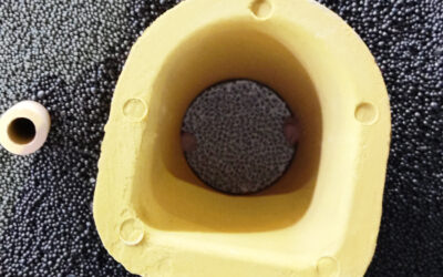
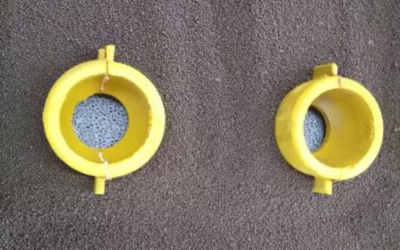
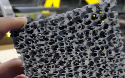
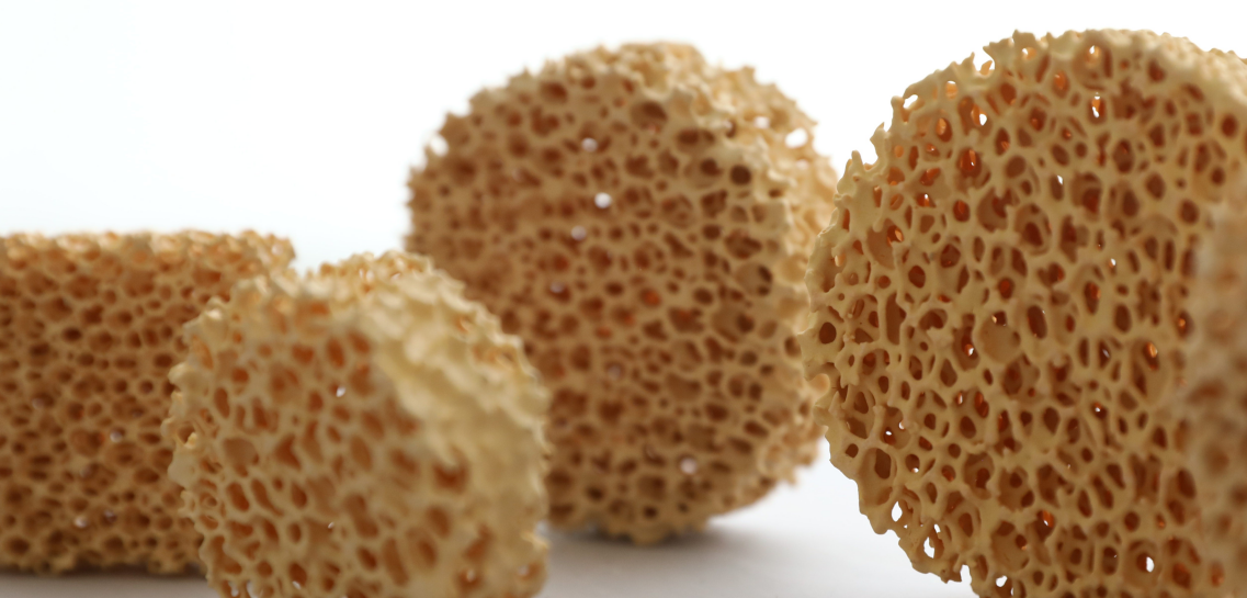
A zirconia Ceramic foam filter for metal casting works through deep-bed filtration rather than surface screening. Inside is a 3D network of interconnected pores and ceramic struts with 80–90% porosity. As molten metal enters, the structure divides it into thousands of micro-streams. Each stream shifts direction repeatedly and brushes against the struts, where suspended inclusions adhere to the ceramic walls.
Three Ways Inclusions Get Trapped
Direct blocking: oxide films, slag particles, and non-metallic inclusions larger than the pore openings cannot pass through.
Inertial impaction: smaller particles fail to follow the sharp bends in the streamline, colliding directly with the zirconia struts and sticking to them.
Surface adhesion: differences in interfacial energy and wetting between inclusions and zirconia cause particles to deposit throughout the internal pore network, well beyond the front face. Higher pore densities capture more inclusions than coarse grades.
From Turbulent Jet to Near-Laminar Flow
Molten metal typically enters the gating system as a turbulent jet. The open-cell structure breaks up this jet, drops its velocity, and recombines the metal into a steady, near-laminar stream on the exit side. This transition prevents free-surface entrainment, jet impingement, and backflow in the mold cavity, helping the mold fill evenly without re-entraining slag.
Calming the flow also cuts gas absorption and secondary oxidation by eliminating velocity spikes, metal splashes, and localized negative pressure. The filter cannot remove gases or oxides that entered upstream; it prevents new oxide skins from forming by keeping the flow smooth.
Parameters That Actually Control Performance
|
Parameter |
Effect of Increasing It |
Engineering Implication |
|---|---|---|
|
PPI |
Smaller pores, higher flow resistance, lower flow rate, better fine-inclusion removal |
10–20 PPI for high flow and coarse inclusions; 30–60 PPI for high cleanliness with higher clogging risk |
|
Pore size |
10 PPI ≈ 2.5–3.0 mm; 20 PPI ≈ 1.2–1.5 mm; 30 PPI ≈ 0.7–0.9 mm |
Pore size is not a hard cutoff; actual capture depends on deep-bed adhesion and inclusion load |
|
Thickness |
Longer flow path, more residence time, more contact area |
25 mm is the standard baseline; 50 mm captures more fine particles but requires higher metal head |
|
Filter area |
Larger total cross-section, lower pressure drop per unit area |
Undersizing causes high velocity, bypass erosion, and early choking; size for peak pour rate, not average |
|
Metal head |
Provides driving force against initial flow resistance |
Aluminum filters (40 PPI, 25 mm) need ~40–80 mm head; high-temperature ceramic foams need ~50–150 mm depending on PPI and surface tension |
|
Inclusion load |
Higher concentration covers pore channels faster |
High PPI cannot replace proper skimming and furnace settling; dirty melts quickly choke fine filters |
In aluminum melts, baseline tests show inclusion removal rates of 85–92% at 30 PPI, 90–95% at 40 PPI, and 93–97% at 50 PPI. Use these numbers as industry benchmarks under specific test conditions rather than universal guarantees for every foundry setup.
The Thermal Conductivity Trade-Off
Zirconia has low thermal conductivity, which works to your advantage during the pour. It insulates the stream and limits heat loss into the filter print and runner walls, protecting steel and nickel alloys that cannot afford to lose superheat.
That insulation does not eliminate the need for proper preheating. If the filter body, seat, or adjacent runner remains cold, incoming metal freezes on contact, forming a chill skin across the entry face or inside the pores. High PPI ratings, tight filter areas, excessive thickness, and low metal head compound this freeze risk by stretching fill times.
Never choose a filter based on temperature rating alone. Balance PPI, thickness, surface area, pour rate per unit area, metal head, and preheat temperature against your target pour time. When targeting high cleanliness, choose a larger filter area with moderate PPI instead of adding thickness. The casting must continue filling smoothly after the metal clears the filter.
Zirconia vs Alumina vs Silicon Carbide: A Full Comparison of Three Filter Materials
Three materials dominate the ceramic foam filter market in metal casting, and none of them wins every match. Picking the wrong one costs more than a bad batch; it costs you the argument when a plant manager asks why the budget jumped.
|
Dimension |
Zirconia (ZrO₂) |
Alumina (Al₂O₃) |
Silicon Carbide (SiC) |
|---|---|---|---|
|
Long-term max use temp |
≤1,700°C; some high-purity grades exceed it |
≤1,100°C; short-term ~1,200°C |
≤1,500–1,550°C; short-term ~1,600°C |
|
Thermal shock performance |
Good to excellent with stabilization; ~≥3 cycles (1,560°C→air) |
Moderate; cracks easier under rapid swings or no preheat |
Excellent; high conductivity, low expansion; ~≥5–6 rapid cycles |
|
Core advantage |
Ultra-high-temp stability, low contamination, resists steel/superalloy attack |
Low cost, chemically stable, fits standard non-ferrous alloys |
Strong thermal shock, conductivity, and mechanical strength; suits iron |
|
Typical alloys |
Carbon steel, stainless, high-manganese steel, nickel/cobalt superalloys |
Aluminum and alloys; some low-temp copper alloys |
Gray iron, ductile iron, CGI; select alloy castings |
|
Cost tier |
High |
Low |
Mid |
Matching Material to Alloy and Pour Temperature
Carbon steel (1,550–1,620°C): Zirconia leads here. This range sits well beyond alumina’s 1,100–1,200°C ceiling and pushes against SiC’s upper edge. Verify structural retention under peak pour conditions rather than relying on melting points from a spec sheet.
Stainless steel (1,580–1,650°C): Zirconia is the safer call. SiC runs at its limit here; treat it as a fallback only with verified field data from actual stainless pours.
Nickel-based alloys (typically above 1,600°C): Use high-purity or stabilized zirconia, paired with dedicated preheat procedures. Nominal maximum temperature ratings do not guarantee success; confirm continuous use temperature and alloy compatibility.
Gray/ductile iron (1,400–1,500°C): SiC wins on thermal shock and conductivity, especially under frequent start-stop cycles. Zirconia works here too, but iron rarely justifies the price jump.
Aluminum alloys (680–760°C): Alumina is the economical choice, sitting well within its ~1,100°C rating. Always preheat; dropping a cold filter into 720–760°C aluminum can crack it from thermal shock alone.
The Rule Nobody Should Skip
The highest temperature rating does not make a filter the best choice. Weigh these factors:
-
Temperature margin: actual pour peak, pour duration, preheat status
-
Thermal shock exposure: frequent cycling often favors SiC over zirconia regardless of melting point
-
Chemical compatibility: steel and nickel alloys require zirconia’s purity; iron benefits from SiC’s conductivity
-
Total cost: filter price, preheat energy, breakage rates, clogging, scrap, and maintenance combined
As a working rule, default to alumina below 1,200°C. Between 1,200°C and 1,500°C, balance SiC’s thermal shock economics against zirconia’s purity advantage. Above 1,500°C, run zirconia, but verify the stabilization grade and direct alloy compatibility before committing.
Why a Higher Temperature Rating Can Transform Casting Economics (From Temperature Rating to Casting Economics)

The real financial return of a higher temperature rating comes from avoiding failure during the pour. alumina filters for aluminum casting run up to 1,050–1,100°C, well above the standard 730–800°C pouring window. Cast iron, copper alloys, and steel have no such buffer. They require silicon carbide or zirconia because thermal shock margins are thin, and thin margins are where foundry cost controls break down.
What Actually Breaks When the Margin Runs Out
|
Failure Point |
Shop-Floor Symptom |
Direct Cost |
|---|---|---|
|
Ceramic fracture |
Insufficient preheat or an excessive pour-to-filter temperature delta cracks the body |
Fragments enter the cavity; line stops, runners get cleared, consumable replaced |
|
Collapse/bypass |
Foam structure crushes, seal fails, metal routes around the filter |
Active filtration area drops, pressure spikes, flow destabilizes batch quality |
|
Inclusion breakthrough |
Oxide film, slag, and ceramic debris pass uncaptured |
Internal inclusions, porosity, surface defects; scrap drops from 3–5% down to 1–2% with proper filtration |
|
Flow interruption |
Clogging, collapse, or sudden flow drop |
Fill time exceeds the window; misruns, cold shuts, plus melting and labor cycle losses |
|
Ceramic contamination |
Fragments or reaction products land in the casting |
Machining exposes hard inclusions, damages tooling, forces rework or scrap on high-reliability parts |
|
Misrun/cold shut |
Metal fronts fail to merge or fill |
Unrecoverable by machining; casting value, melt, mold cycle, and inspection cost all lost |
Failures also carry delayed expenses. Inclusions do not always show up immediately after the pour. They surface during machining, leak testing, fatigue testing, or in the field, where warranty claims and returns multiply the initial scrap loss.
Running the Total Cost of Ownership
$$TCO = C_f + C_i + C_e + C_r + C_s$$
-
C_f: filter purchase cost (unit price, freight, inventory, replacement frequency)
-
C_i: installation cost (preheat, placement, sealing, labor, downtime)
-
C_e: energy cost (filter preheat, added insulation, reheat from restricted flow)
-
C_r: rework cost (cleanup, machining, weld repair, re-inspection, labor)
-
C_s: scrap cost (casting value, melted metal, mold cycle, disposal)
Filter consumables represent 0.5–2.0% of casting production value, while scrap reductions from quality improvements can return 3–10x the filter cost itself. A higher-rated filter costs more per unit, but it lowers overall production expense by eliminating fractures and line stops.
Two Numbers That Settle the Argument
Case A: Across 60,181 castings, reducing the scrap rate from 8% to 3.93% is a 4.07-point drop, or roughly 2,449 fewer scrapped units. At $50 per unit, that saves $122,450 annually. At $100 per unit, the savings reach $244,900, before accounting for rework, downtime, or customer returns.
Case B: When scrap drops from 4% to 1.5%, you lose 250 fewer units per 10,000 produced. At $80 per unit, that saves $20,000. If the upgraded filter adds $1 per casting, breakeven volume is 0.5 units. Factor in preheat, installation, and downtime costs, and the math favors the upgrade in nearly every scenario.
Best-Fit Applications for High-Temperature Alloys
Four alloy families separate zirconia from every other filtration option on the foundry floor. Miss the PPI or temperature margin on any of them, and you risk a part that costs far more to remake than the filter itself.
Carbon and low-alloy steel pours at 1,550–1,620°C. Large-section or long-flow-path castings need zirconia at 10–20 PPI to balance flow against choking. Past 1,560°C or during longer contact times, zirconia outperforms silicon carbide on chemical stability alone.
Stainless steel pours at 1,550–1,650°C depending on the grade and part size. Standard jobs take zirconia at 10–20 PPI. Precision castings with tight surface and fatigue requirements warrant stepping up to 20–30 PPI, provided you recalculate metal head and filter area first.
Nickel-based superalloys usually pour at 1,400–1,550°C. For thin-wall blades and aerospace components, ceramic shedding and thermal shock resistance matter far more than the pour temperature itself. Run high-purity or partially stabilized zirconia at 20–40 PPI, rated for continuous service at 1,650–1,700°C minimum to preserve that 50°C safety buffer.
Cobalt-based superalloys and specialty steels stay in that same 20–40 PPI window, particularly under high superheat or in long, narrow channels.
|
Casting Scenario |
Recommended Filter |
Selection Priority |
|---|---|---|
|
Standard carbon/low-alloy steel parts |
Zirconia, 10–20 PPI |
Low pressure drop, sufficient flow |
|
Heavy structural steel castings |
Zirconia, 10–20 PPI, parallel units if needed |
High flow, anti-clogging, thermal shock resistance |
|
Stainless valve bodies, pump housings |
Zirconia, 10–30 PPI |
Reduced oxide inclusions, surface defects |
|
Nickel turbine/guide vanes |
High-purity zirconia, 20–40 PPI |
Low inclusion, low ceramic contamination |
|
Aerospace precision castings |
High-reliability zirconia, 20–40 PPI |
Filtration efficiency, traceable failure data |
|
Petrochemical high-temp valves |
Zirconia, 10–30 PPI |
Corrosion resistance, extended contact time |
|
Large power generation castings |
Zirconia, 10–20 PPI or parallel |
High throughput, thermal cycling stability |
Why Failure Cost Drives the Decision Here, Not Filter Price
Scrapping a turbine blade, gas turbine component, petrochemical valve, or power plant casting wastes far more than raw material. It burns through melting, mold preparation, machining, NDT time, delivery schedules, and batch traceability. Inclusions in nickel alloys often turn into fatigue crack origins, so aerospace and power generation buyers accept higher filter costs to secure lower rework rates and clean NDT results. Zirconia operates reliably at 1,650–1,750°C across steel, superalloy, and nickel/cobalt melts, providing thermal headroom that reduces mid-pour fracture risk. In high-value runs, consistency matters more than unit price. One saved casting pays for the premium many times over.
Four Conditions That Push You Toward Zirconia
-
Extended contact time: Long pours, low flow velocity, deep cavities, filters in series, or metal dwelling ahead of the filter. Chemical stability matters more than nominal temperature ratings here.
-
Severe thermal cycling: Preheat, dwell, sudden fill, and intermittent pours. Preheat to 600–800°C and verify a documented thermal shock grade to prevent cracking under rapid thermal shifts.
-
High inclusion loading: High return scrap ratios, oxide-rich melts, turbulent handling, or long ladle transfers. Start at 10–20 PPI, and increase density only after expanding the filter area to avoid choking.
-
Aggressive melt chemistry: High-chromium stainless, nickel/cobalt alloys, or reactive alloying elements. Above roughly 1,600°C, or anywhere SiC risks reacting with the melt, zirconia is the safer material.
Thin-wall, critical parts like turbine blades, hot-end gas turbine components, petrochemical valve bodies, and power generation castings fall into this category. Prioritize low ceramic shedding, full batch certification, and a working temperature rating safely above your actual pour peak.

Procurement Checklist for Zirconia Ceramic Foam Filters
Before signing a purchase order, demand the paperwork that verifies a zirconia ceramic foam filter for metal casting rather than relying on marketing claims.
Composition and traceability. Published benchmarks for steel-grade filters run ZrO₂ 85–90%, Al₂O₃ 5–10%, SiO₂ ≤4%, and MgO 4–5%. Require batch-level chemical analysis, raw material lot numbers, furnace trace records, and RoHS/REACH declarations.
Thermal shock data. The industry benchmark calls for ≥6 cycles between 1,100°C and room temperature without through-cracks or spalling. Make sure the supplier provides documented compressive strength retention measured before and after cycling.
Compressive strength. Room-temperature ratings usually run ≥1.2–1.5 MPa, though some PSZ datasheets report ≥1.75 MPa. Set your incoming inspection floor at ≥1.2 MPa, and treat anything under 1.0 MPa as a high breakage risk. Demand the average, minimum, standard deviation, and sample size rather than a single “typical value.”
Dimensions and capacity. Pore sizes span 4–60 PPI, with 10–40 PPI standard for steel and high-alloy pours. Porosity runs 80–90%, and thickness spans 13–25 mm. A 100×100×22 mm filter should handle a rated throughput near 120 kg at 9.8 kg/s, while a 50×50×22 mm unit handles around 55 kg at 2.6 kg/s. Request specific PPI tolerances (such as 10±2), flatness limits, edge-chip limits, and seat compatibility.
Documentation. Collect ISO 9001 certification, SDS, per-batch COAs, calibration records, and clear claim terms for breakage, clogging, or dimensional deviation.
Validation Before You Scale Up
Run a controlled A/B trial comparing your current filter to the zirconia candidate across at least 30–50 heats using the same alloy, pour temperature, and crew. Track failure rates, inclusion defects, scrap and rework rates, yield, pour interruptions, and the final cost per good casting. Score suppliers on a weighted basis: quality and safety at 40%, actual filtration performance at 25%, stability and failure rate at 15%, cost at 15%, and documentation at 5%. If ceramic fragments enter a casting, suspend that supplier for 8D corrective action before another order ships.
Conclusion
The math is straightforward, but purchasing teams often overlook it. zirconia ceramic foam filters cost more upfront than alumina or silicon carbide alternatives, sometimes by a wide margin. Yet when you factor in scrap rates, rework hours, and premium alloy losses, that price gap shrinks or disappears. The highest temperature rating in the category determines whether your filter survives the pour or leaves you explaining a failed heat to your plant manager.
If you’re casting superalloys, high-chrome steels, or anything above 1600°C, don’t let unit price drive the decision. Pull your last six months of rejection data, map it against filter failures, and run the TCO comparison for yourself. Then talk to FoundryMax about a trial run on your next high-temperature pour. The numbers will make the case better than we can.