Every failed casting tells a story — and that story almost always starts at the gating system. Skip the basics of how the sprue, runner, and riser each work, and you’re guessing through a process with zero margin for error. That’s a risk no foundry can afford.
The gap between a flawless part and a scrapped one comes down to one thing: how well molten metal moves, spreads, and feeds during solidification. Get that wrong, and defects show up fast.
This breakdown of sprue vs runner vs riser covers exactly that — what each component does, where it sits in the system, and how smart gating design stops the defects that eat into casting quality before you even spot them.
What Is a Gating System in Sand Casting (And Why It Controls Everything)
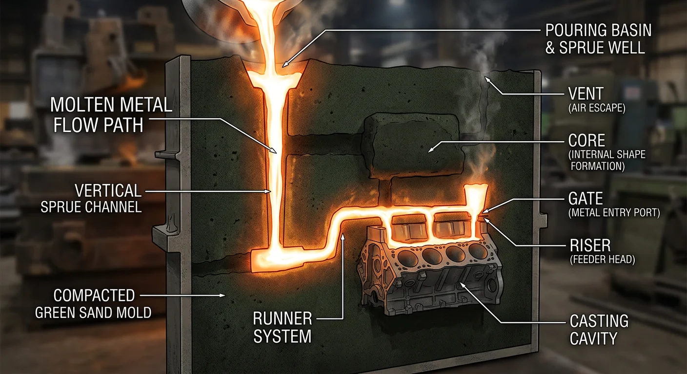
A gating system is the engineered pathway that moves molten metal from the ladle into the mold cavity. Every component in that path has a specific job to do.
In sand casting, you can’t pour metal straight into a closed mold. There’s no open access point. Try it anyway, and you get instant turbulence. Air gets pulled into the stream. Defects form before the metal even reaches the cavity. The gating system exists to stop all of that.
Here’s what it does:
-
Controls metal velocity — the target is ≤1 m/s through the runner and gates. Too fast, and you get sand erosion and gas entrapment. Too slow, and the metal solidifies before the cavity fills.
-
Maintains laminar flow — turbulent flow introduces dross, oxidation, and air pockets. Laminar flow keeps the metal clean and consistent.
-
Traps slag and inclusions — slag floats to the top. So the runner extension sits lower than the in-gates, catching contaminants before they reach the cavity. Ceramic filters in the runner add another layer of protection.
-
Directs solidification — the system manages temperature gradients so the casting solidifies in the right order. This reduces shrinkage porosity and keeps the final part structurally sound.
The choke area is the tightest point in the system. It’s what regulates flow rate. The formula is straightforward: CA = 22.6 × W (where W is casting weight in kg). That one measurement sets pour time and velocity across the whole system.
Think of it as traffic control for liquid metal. No gating system means no predictability — and no predictability means defects.
Sprue: The Entry Point That Sets the Flow in Motion
The sprue is where everything begins — and where most gating problems start.
It’s a vertical conical channel. The widest end sits at the pouring cup or basin and connects to the nozzle. The narrow base feeds into the runner or straight toward the cavity. That taper isn’t cosmetic. It’s functional. A standard taper angle of 2°–5° does two things at once: it makes ejection clean and keeps the metal moving in the right direction.
Why Taper Is Non-Negotiable
A straight cylindrical sprue looks simpler on paper. In practice, it’s a defect generator.
Metal enters a straight sprue and velocity drops mid-channel. Pressure gradients collapse. Vortices form at the base. Air gets pulled in — not by accident, but by physics. The result is turbulent flow with a Reynolds number exceeding 4000. Defect rates run 20–30% higher than tapered designs.
A tapered sprue works the opposite way. The narrowing cross-section keeps accelerating the metal — from entry velocities around 1–2 m/s at the basin up to 5–10 m/s at the base. That steady gradient maintains laminar flow. It cuts air aspiration by over 50% and keeps fill uniformity above 95%. A straight sprue? That number drops to 70–80%.
Sizing the Sprue Right
The math behind sprue sizing is simple: v = Q/A, where Q is volume flow rate and A is cross-sectional area.
Standard dimensions for a tapered sprue:
– Top diameter: 6–10 mm
– Base diameter: 3–6 mm
– Length: keep it under 100 mm to prevent freeze-off
– Base-to-runner area ratio: 1:2 to 1:4
Target entry velocity sits between 0.5–1.5 m/s. Push past that, and you get sand erosion. Drop below it, and premature solidification kills fill rates.
Each sizing error has a direct, measurable cost:
|
Error |
Defect |
Impact |
|---|---|---|
|
Undersized sprue |
Short shots, incomplete fill |
30% reject rate |
|
Oversized sprue |
Excess waste, extended cycle time |
+20% cycle time, 15% material waste |
|
No taper |
Jetting, mold erosion |
Erosion 0.1–0.5 mm/cycle; porosity in 10–25% of parts |
|
Poor alignment |
Gas porosity, air pockets |
5–15% void volume |
A well-designed sprue keeps waste below 5% of shot weight. It also holds pressure drop to 10–20% across the total system. Get those numbers right, and everything downstream — runner, gates, riser — has a real chance of working the way it should.
Runner: The Distribution Network That Feeds Every Cavity
Molten metal clears the sprue base and hits the runner system. That’s where distribution either works or falls apart.
The runner is a horizontal channel network. It moves metal from the sprue base to every gate feeding the mold cavity. The job sounds simple: get the right amount of metal to the right place at the right time, every single pour. But getting that right takes real precision.
Layout Logic: Matching Design to Cavity Count
Runner layout is not one-size-fits-all. The geometry changes based on how many cavities need feeding:
-
Radial designs — balanced flow, lower overall feed volume, best for simpler configurations
-
H-branching (hierarchical) — built for 8–16 cavities; primary channels run largest near the sprue base, then taper step by step as branches split off
-
Symmetrical arrangements — equal path lengths from sprue tip to each cavity end; this is the foundation of a well-balanced system
The hierarchy follows a consistent rule: primary channels carry more than secondary, which carry more than tertiary. Double gates, for example, halve flow rate and speed. You can then increase injection velocity to maintain viscosity without introducing turbulence.
Balancing: Where Most Multi-Cavity Problems Get Fixed
Unbalanced runners are a quiet defect engine. Near-sprue cavities fill first. End cavities starve. The result is warping, underfill, and dimensional inconsistency across the batch.
A solid balancing approach works in five steps:
-
Arrange cavities in a symmetrical pattern around the sprue
-
Calculate equal runner diameters and lengths for consistent flow resistance
-
Select the appropriate cold or hot runner type
-
Run a Moldflow simulation to predict pressure and fill behavior
-
Run trials to fine-tune sizes and temperatures
One detail that often gets missed: shear heating at channel perimeters creates uneven viscosity at branch points. Hotter, less viscous metal tends to favor one side of the split. Trapezoidal or round cross-sections reduce that asymmetry. They keep flow balanced across the full cavity count — from 2-cavity tooling all the way up to 32.
Riser: The Shrinkage Compensator That Saves the Casting
Shrinkage gives no warning. Metal fills the cavity. The pour looks clean. Everything seems fine — then the casting cools, contracts, and leaves a void right where you can’t afford one.
That’s the problem the riser sleeve solves.
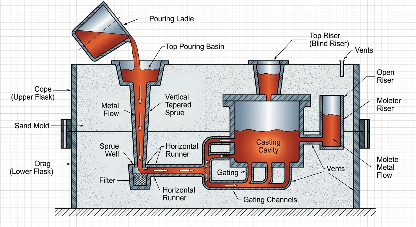
A riser is a built-in reservoir of molten metal. It stays liquid longer than the casting it feeds. As the part solidifies and volume drops, the riser pushes metal into the shrinking sections. No riser means no compensation — just voids, porosity, and parts that fail inspection before they reach the customer.
Where Risers Go (And Why Placement Is Everything)
Put a riser in the wrong spot and it feeds nothing. The rule is simple: risers sit at the thickest sections of the casting. Thick sections hold heat the longest. They solidify last. That’s where shrinkage builds up.
The core principle is “last to solidify.” The casting riser must stay molten longer than the heaviest section it feeds. The casting solidifies first, the feeding path closes, and shrinkage voids form — that’s the failure you want to avoid.
Hollow castings need more than one riser. A single riser can’t cover the whole cavity. Multiple risers — top, middle, lower — keep the feeding paths open and stop large cavities from forming at the base.
What a Riser Does
Shrinkage compensation is the main job, but not the only one:
-
Feeds liquid metal into contracting sections during solidification
-
Vents gases out of the mold cavity as metal fills
-
Traps slag and inclusions before they reach the casting structure
-
Ensures complete fill before solidification locks the cavity
High-shrinkage alloys — cast steel, manganese brass, aluminum bronze — put the most stress on riser design. Their volume shrinks so much during cooling that a riser that’s too small or in the wrong place will produce defective parts, every time.
Controlling the Outcome
Riser performance comes down to heat management. The target is directional solidification — the casting solidifies in stages, moving toward the riser. Get that right, and the riser feeds shrinkage from one end to the other without gaps.
Mold insulation, material choice, and preheating all shape the cooling rate. Casting simulation software takes out the guesswork. It predicts solidification behavior before the first pour, so engineers can set the right riser size, count, and placement with confidence.
Get it right and you end up with dense, compact castings. No shrinkage cavities. A structure that holds up under load.
Sprue vs Runner vs Riser: Side-by-Side Comparison
Three components. One system. Each with a job so specific that failing any one of them ruins the whole pour.
Here’s the clearest way to see how sprue, runner, and riser divide the work:
|
Component |
Primary Function |
Position in System |
|---|---|---|
|
Sprue |
Main inlet from furnace to mold |
Vertical entry point — first contact |
|
Runner |
Distribution channels to cavities |
Horizontal network — lateral spread |
|
Riser |
Molten metal reservoir during solidification |
Strategic feed points — last to freeze |
The sprue is the main artery. It’s a large-diameter vertical channel. Molten metal hits it first, the moment it enters the mold. The runner is a network of shallow channels cut into the mold face. These channels connect the sprue base to each cavity. The riser sits apart from both. It’s not a flow channel. It’s a reservoir that stays liquid on purpose.
How They Work in Sequence
The filling order isn’t random. It’s a planned progression:
-
Sprue fills first — metal enters, velocity builds, flow establishes
-
Runners distribute — metal spreads out to each cavity
-
Cavities fill — the actual part takes shape
-
Riser holds last — stays molten to feed shrinkage as the casting cools
All three need the right size and position for this sequence to work. Break the chain at any point, and defects pile up fast.
What Goes Wrong When Design Fails
Each component has its own failure mode. Each failure also leaves a clear mark on the scrapped part:
|
Design Error |
Component |
Result |
|---|---|---|
|
Oversized sprue |
Sprue |
Excess turbulence → trapped gas → inclusions |
|
Undersized runner |
Runner |
Inadequate fill → misruns, cold shuts |
|
Insufficient riser volume |
Riser |
Shrinkage cavities, internal voids |
|
Poor runner distribution |
Runner |
Pressure imbalance, uneven cavity fill |
|
Wrong riser placement |
Riser |
Localized shrinkage in critical sections |
Runner cross-sections are rectangular or circular in most cases. Gate area ratios to the runner run between 0.03–0.09. These numbers aren’t arbitrary. They control friction, feed rate balance across cavities, and internal stress in the finished part. Get them wrong, and the part fails — even if everything else looks right.
The sprue is the one element you can’t skip. A direct sprue gate can cut out runners altogether. But runners and risers are what push a part from “acceptable” to “reliable.” Drop either one from your design, and you’re leaving quality up to chance.
Pressurized vs Non-Pressurized Gating Systems: Which Design Fits Your Casting?
Choosing between pressurized and non-pressurized gating is not about preference. It’s an engineering decision with real, measurable consequences for every pour.
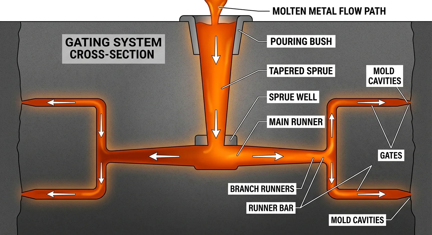
Both systems use the same components: sprue, runner, in-gate. The difference is where the choke sits. That one factor changes how metal moves through the whole system.
Where the Choke Lives Changes Everything
In a pressurized system, the choke sits at the in-gate. That’s the smallest cross-section in the entire path. The restriction builds back pressure. It keeps the sprue and runner full during the pour. This forces equal flow volume across every in-gate in the system.
In a non-pressurized system, the choke sits at the sprue base. Metal velocity drops step by step — from the sprue, down through the runners, and into the gates. No back pressure builds. Flow runs free.
That’s the core difference. Everything else — fill speed, inclusion behavior, yield, defect rate — follows from it.
Pressurized: Fast, High-Yield, and Turbulent
Pressurized systems fill fast. Pour times run 7–9 seconds, driven by higher velocity and sized-down runners and in-gates. That speed improves casting yield. It also makes pressurized designs the right call for complex geometries, thin sections, and high-pressure processes like die casting.
The tradeoff is turbulence. Traditional pressurized systems pull in more than 5× the air volume compared to non-pressurized designs. More turbulence means more aspiration, more inclusions, and larger slag particles reaching the cavity. Ductile iron and large, heavy castings handle this better than most other materials.
Non-Pressurized: Clean Flow, Lower Yield
Non-pressurized systems trade speed for cleanliness. Fill times stretch to 10–11 seconds. The slow, steady flow cuts turbulence, erosion, and oxidation by a wide margin. Vertical in-gates catch inclusions before they reach the cavity. Entrained air volume drops to less than one-fifth of a pressurized setup.
Aluminum and other oxidation-sensitive alloys belong here. Simple, thick-walled geometries get the most benefit. The downside is yield — larger, less-optimized runners and gates burn through more material per pour.
Reading the Ratios
Gating ratios give you a clear way to classify your system. Check the sprue:runner:in-gate area as your starting point:
|
System |
Typical Ratio |
Area Progression |
|---|---|---|
|
Pressurized |
1 : 1.2 : 1.4 |
Decreases → in-gate smallest |
|
Non-Pressurized |
1 : 2 : 1.4 |
Increases → sprue smallest |
In-gate is the smallest area? You’re running pressurized. Sprue is smallest and the runner expands outward? That’s non-pressurized. Calculate those areas before you commit to a design. The numbers show you which system you’ve built — no matter what the drawing says.
|
Aspect |
Pressurized |
Non-Pressurized |
|---|---|---|
|
Pour Time |
7–9 seconds |
10–11 seconds |
|
Entrained Air |
>5× higher |
Much lower |
|
Inclusions |
More, larger |
Fewer, gate-trapped |
|
Casting Yield |
Higher |
Lower |
|
Best For |
Complex/thin sections, ductile iron |
Aluminum, thick geometries |
Match the system to your alloy and geometry — not the other way around.
Common Gating System Defects and How Proper Design Prevents Them
Five defects cause most scrapped sand castings. Every single one traces back to a poorly designed gating system.
Gas porosity starts with turbulent flow pulling air into the metal stream. Once the Reynolds number passes 2000, flow turns chaotic. Hydrogen porosity follows. The fix is straightforward: place ceramic filters upstream in the runner and use low-turbulence fill sequences. In aluminum castings, pairing ceramic filters with spin traps has cut surface defects by 65%. In some 3D-printed sand mold applications, that result came from reducing ingates from five down to three.
Shrinkage porosity shows up when metal cools at uneven rates. Slow fill causes premature solidification in thin sections before the cavity is packed. A tapered sprue fixes this by holding uniform velocity through the full fill. Risers at hot spots cover the rest. Keep your runner-to-ingate area ratio between 2:1 and 4:1 — this removes most of the starvation risk.
Slag inclusions enter the cavity when velocity runs too high and nothing in the path catches them. Runner extensions solve this. They absorb kinetic energy after the choke and let slag float up before metal reaches the ingate. Gated wells, spin traps, and filters add extra layers of protection on top of that.
Cold shuts form when thin sections lose heat before the cavity finishes filling. You can push fill time into a safe range by:
– Increasing gate area
– Shortening runner length
– Preheating the mold
The goal is to complete the pour before 70% solidification locks the flow path.
Sand inclusions come from high-velocity metal eroding the mold walls. Proper choke sizing and smooth channel transitions keep pressure low enough to stop this from happening.
Why Permanent Gating Closes the Gap
One overlooked fix is mounting the gating system straight onto the pattern. This locks out human variation from mold assembly. Sprue position, runner dimensions, ingate area — all fixed, every pour, no guesswork.
The payoff is real. Documented aluminum housing applications show defect reductions of 40–65% with repeatable flow rates. Curved internal gating in 3D-printed patterns also cuts post-processing time by 40%. Cleaner fills mean less cleanup after each pour.
Same geometry, same outcome — every time. That’s the case for permanent gating, and the numbers back it up.
Conclusion
Every casting starts with a decision you make before the metal moves — and that decision lives in your gating system design.
The sprue controls entry velocity. The runner spreads flow evenly. The riser makes up for what physics takes away. Get all three working together, and you get clean, defect-free castings. Miss the connections between them, and shrinkage, turbulence, and incomplete fills become your quality control headache.
Sprue vs runner vs riser isn’t just theory — it’s the difference between a casting that ships and one that gets scrapped.
So here’s your next move: audit your current gating system against what you’ve just learned. Are your runners sized for your flow rate? Is your riser volume large enough? Small adjustments here add up to real yield improvements over time.
The gating system controls everything. Now you control the gating system.